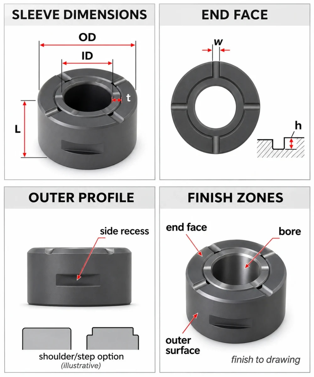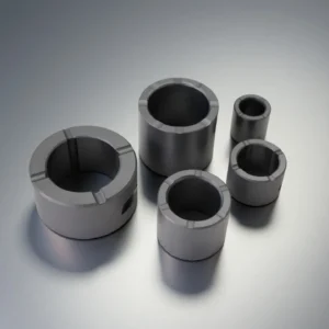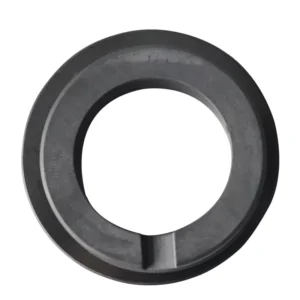
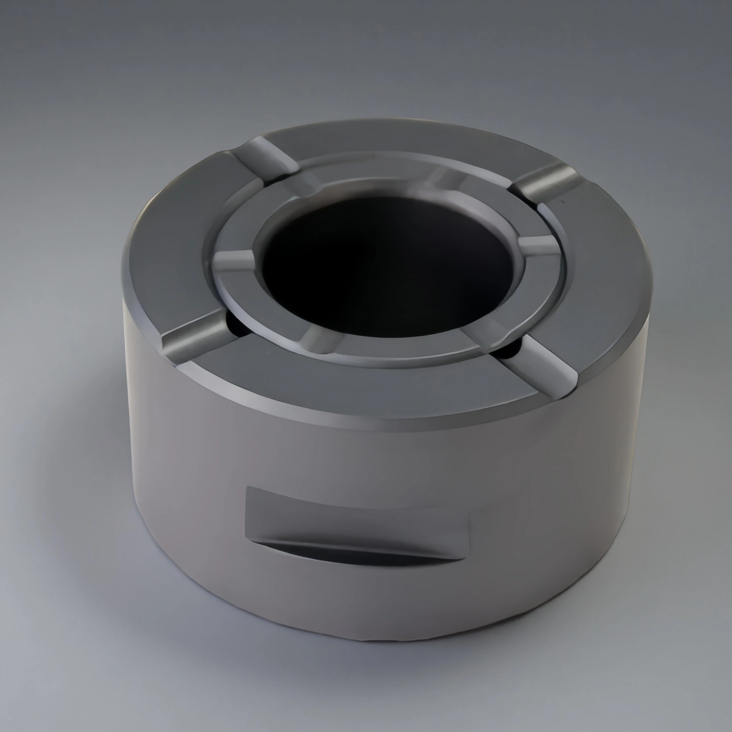
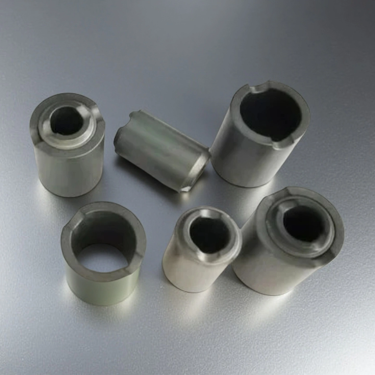
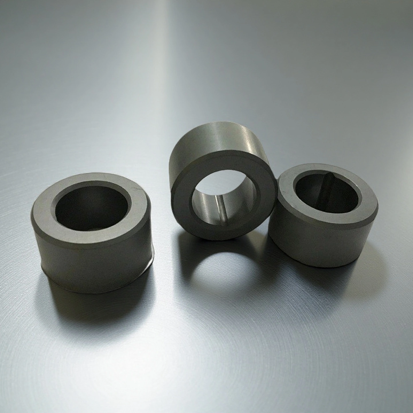
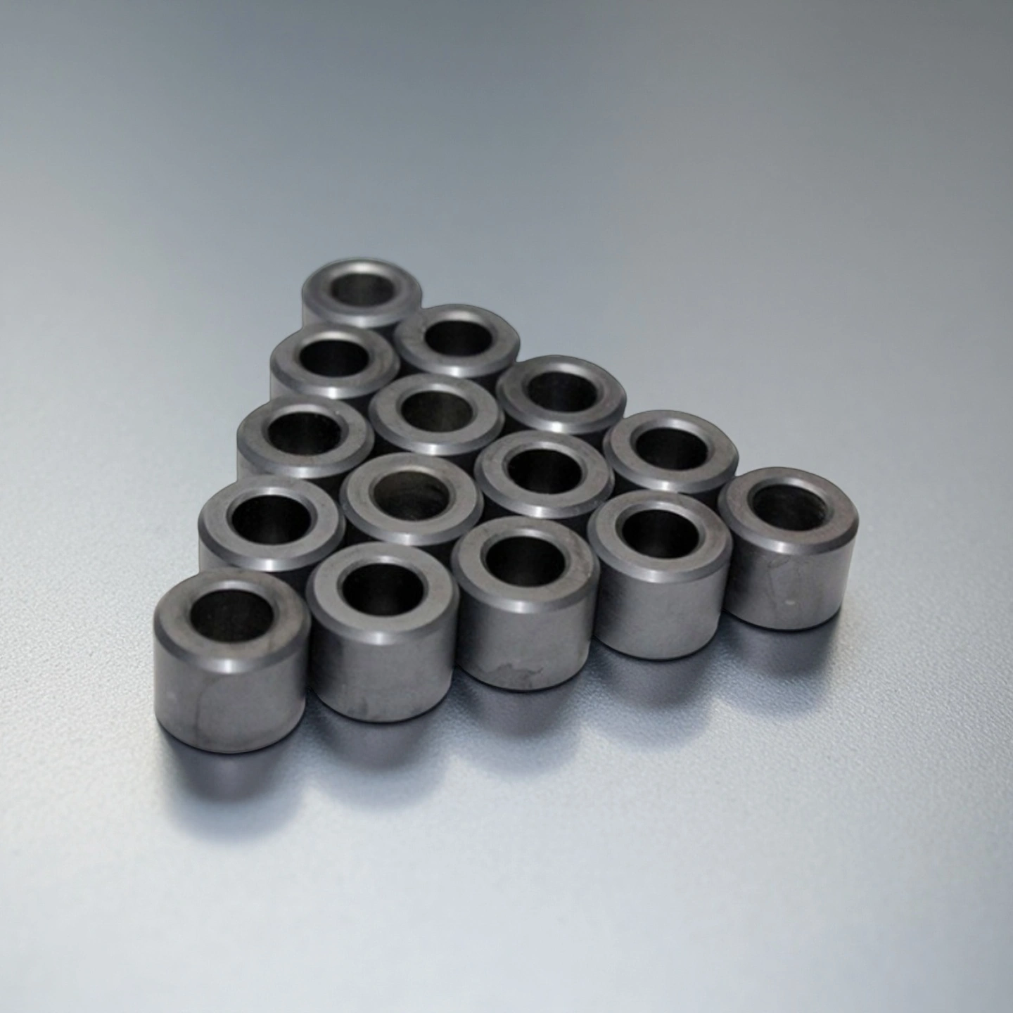
A silicon carbide shaft sleeve sits on the shaft to protect the contact or exposed zone at that position — at a seal, a bearing housing or a process zone. The sleeve defines its own bore, outer profile, end features and working surfaces; the shaft, bearing and mechanical seal remain separate parts with their own fits. Four SiC routes are available: dense SSiC, reaction-bonded RBSiC, silicon-nitride-bonded NBSiC and recrystallized RSiC, named on the drawing and the order.
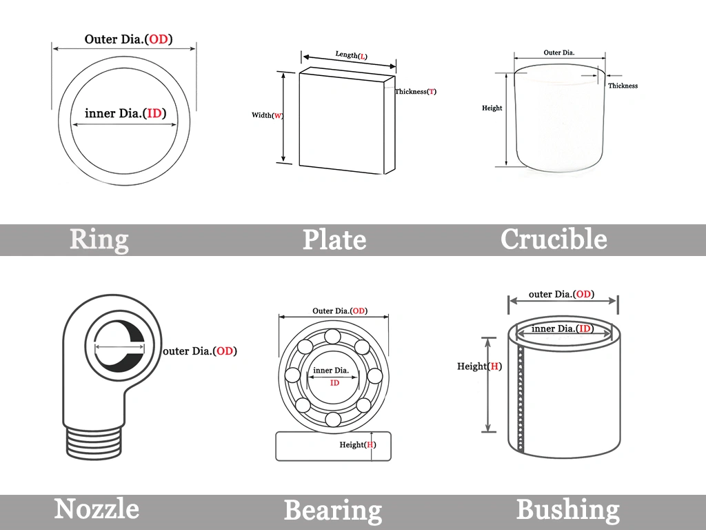
Dimensions of Silicon Carbide Ceramic Shaft Sleeve
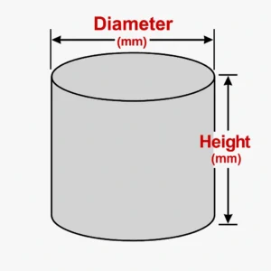
| Silicon Carbide Ceramic Shaft Sleeve | ||||
| Item No. | Outer Diameter (mm) | Inner Diameter (mm) | Length (mm) | Purity(%) |
| AT-SCS-001 | 19 | 8 | 42 | 99 |
| AT-SCS-002 | 16 | 10 | 42 | 99 |
| AT-SCS-003 | 14 | 8 | 42 | 99 |
| AT-SCS-004 | 18 | 8 | 45 | 99 |
| AT-SCS-005 | 22 | 14 | 51 | 99 |
| AT-SCS-006 | 23 | 11 | 51 | 99 |
| AT-SCS-007 | 26 | 12 | 51 | 99 |
| AT-SCS-008 | 29 | 20 | 56 | 99 |
| AT-SCS-009 | 28 | 14 | 60 | 99 |
| AT-SCS-010 | 35 | 20 | 70 | 99 |
| AT-SCS-011 | 45 | 34 | 85 | 99 |
| AT-SCS-012 | 44 | 25 | 108 | 99 |
| AT-SCS-013 | 57 | 30 | 108 | 99 |
| AT-SCS-014 | 68 | 42 | 108 | 99 |
| AT-SCS-015 | 49 | 28 | 108 | 99 |
| AT-SCS-016 | 80 | 60 | 108 | 99 |
| AT-SCS-017 | 110 | 88 | 108 | 99 |
| AT-SCS-018 | 130 | 110 | 108 | 99 |
| AT-SCS-019 | 140 | 123 | 108 | 99 |
| AT-SCS-020 | 175 | 140 | 140 | 99 |
Silicon carbide material data by route
The figures below are material selection values from the ADCERAX SiC data sheet, measured on test specimens under the stated conditions. They describe the material route, not the finished sleeve.
| Property | Unit/condition | RBSiC | SSiC | NBSiC |
|---|---|---|---|---|
| SiC content | wt% | 85 nominal | ≥99 | 80 nominal |
| Bonding phase | — | 15 wt% residual free silicon | No silicon-infiltration phase | 20 wt% Si₃N₄ bond |
| Bulk density | g/cm³ | ≥3.02 | 3.10 typical | 2.80 typical |
| Open porosity | vol% | ≤0.1 | <0.1 | 12 typical |
| Flexural strength | MPa | 250 at 20 °C | 380 | 160 at 20 °C |
| Compressive strength | MPa | / | ≥2600 | / |
| Young's modulus | GPa | 330 at 20 °C | 420 | 220 at 20 °C |
| Poisson's ratio | — | / | 0.16 | / |
| Thermal conductivity | W/(m·K) | / | 100–120 | 15 at 1000 °C |
| Application-temperature ceiling | °C, initial selection | 1380 | 1600 | 1550 |
How to Choose a Silicon Carbide Shaft Sleeve
Start with the situation that matches your project. Missing details can be completed during drawing review.
1. New Pump or Rotating Equipment
Define the sleeve around the shaft, housing and seal arrangement.
- Dimensions: Shaft diameter and tolerance, housing bore, and sleeve position.
- Assembly: Seal or bearing location, axial retention, and process medium.
- What to send: An assembly drawing or 3D model with the sleeve position marked.
2. Replacing a Worn or Failed Sleeve
Use intact surfaces to establish the original geometry. Photograph worn or damaged areas separately.
- Dimensions: Shaft-fit bore, locating faces, outer working surface, grooves and recesses.
- Condition: Wear location and damage to the sleeve or mating parts.
- What to send: Photos with measurements, plus the equipment model and part number if available.
3. Purchasing to an Approved Specification
Confirm the drawing revision, material requirements and inspection scope before ordering.
- Material: SiC grade or manufacturing route and batch identification.
- Acceptance: Required checks for the material, finished sleeve and assembly, where applicable.
- What to send: The approved drawing, quantity and your QA inspection requirements.
Standard or Custom?
- Standard sleeve: Check that the listed dimensions and specifications match your assembly.
- Custom sleeve: Define the fit, working surfaces and features on your drawing.
Compare lead time, drawing requirements and price before choosing.
Silicon Carbide Routes and Alternative Ceramics
SiC grades differ in bonding phase and porosity. Choose the route to match the sleeve geometry, working surface and process medium.
SSiC — Precision Fits and Finished Surfaces
Dense, pressureless-sintered SiC with no free-silicon phase.
- Suitable for: Precision bores, ground or polished surfaces, and controlled edges.
- Check: Size and shape feasibility, especially for large or complex sleeves.
RBSiC / SiSiC — Larger or Complex Profiles
Reaction-bonded SiC containing residual free silicon.
- Suitable for: Larger sleeves and complex shapes produced close to their final dimensions.
- Check: Chemical compatibility of the residual silicon with the actual process medium.
NBSiC — Thermal and Structural Applications
A porous SiC material bonded with silicon nitride.
- Suitable for: Thermal-processing components and selected structural sleeves.
- Check: Whether open porosity is acceptable for fluid contact, permeability and sealing.
RSiC — Thermal Cycling Applications
A porous, recrystallized SiC structure used in kiln and thermal-processing equipment.
- Suitable for: Applications requiring performance through repeated heating cycles.
- Check: Component-specific porosity, strength at operating temperature and permeability.
When to Consider Another Ceramic
- Alumina: A lower-cost option for moderate wear and less aggressive media.
- Zirconia: Consider where toughness and resistance to edge chipping matter.
- Silicon nitride: Consider for rolling contact or demanding thermal cycling.
Three Checks Before Selection
- Medium: Is it compatible with the SiC route and its bonding or residual phases?
- Surface: Does the sleeve require a precision fit, a sealing surface or general wear protection?
- Geometry: Can the selected route achieve the required size, shape and tolerances?
Send the drawing, process medium and mating-part details to confirm the choice.
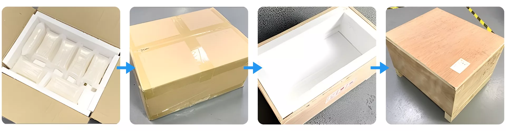
Packaging Process for Silicon Carbide Ceramic Shaft Sleeve
Shaft sleeves are packed with the bore and end faces protected, and separate sleeves are held apart so they cannot contact each other in transit.