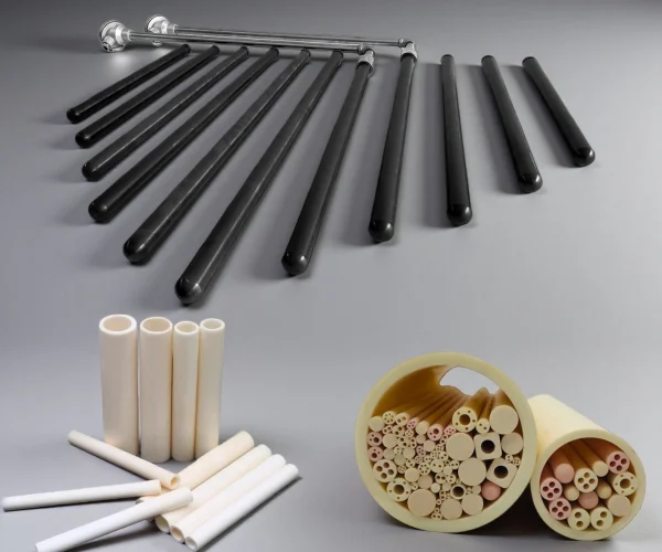
Ceramic Thermocouple Protection Tubes for Stable, Low-Drift Measurement
Ceramic thermocouple protection tubes shield the sensor junction from furnace gases, deposits, molten metal and mounting stress, so measurement stays accurate with fewer replacements and less downtime.
The right choice is a material route — alumina, mullite, silicon carbide, silicon nitride / Sialon or zirconia — matched to your temperature, atmosphere and failure mode.
Thermocouple Tube Failure Causes
Thermocouples in furnaces and reactors often fail early when the hot zone combines high heat, corrosive vapors, and frequent thermal cycling.
Metal sheaths can oxidize, scale, or carburize, which alters heat transfer and gradually shifts temperature readings. In reactive atmospheres, deposits and vapors can contaminate noble-metal thermocouple wires, increasing drift and accelerating calibration loss.
Fast transients, such as door-open events, purge changes, or aggressive ramp rates, can crack brittle protection parts when clearance, alignment, and mounting compliance are not controlled.
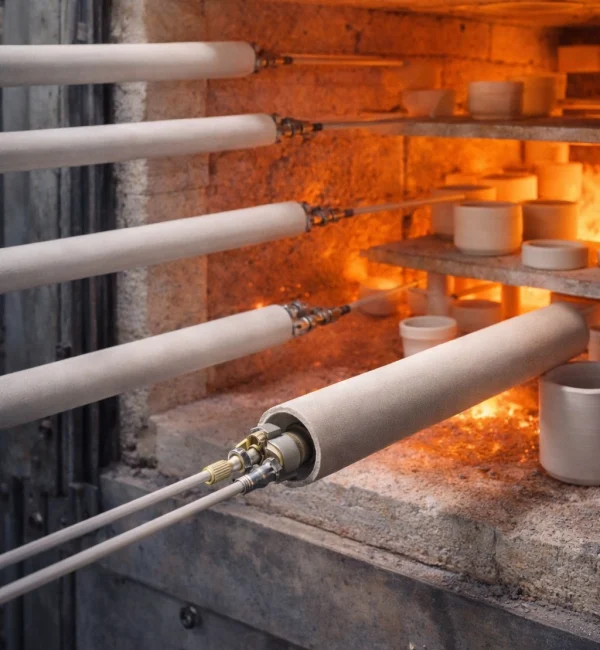
Why Thermocouple Protection Tubes Fail in Service
In high-temperature service, thermocouples often drift before they fail. Reactive vapors and deposits can change junction conditions, while thermal cycling and constraint can crack the protection tube and shift alignment.
Thermal shock and temperature gradients
rapid insertion, door opening, and fast ramp cycles drive steep gradients across the tube wall, initiating cracks at the closed end or near support points.
Chemical attack and vapor transport
alkali vapors, glassy phases, fluxes, and process volatiles can react with the tube or migrate through micro-porosity, reaching the thermocouple junction.
Contamination-driven drift
at high temperature, small amounts of vapor exposure can change junction conditions and shift EMF output, especially in long-duration holds.
Mechanical stress and constraint
tight fits, misalignment, or differential expansion between tube and mounting hardware create bending stress and edge chipping.
Creep/softening of non-ceramic supports
metal holders or thin shields can deform at temperature and force the tube into contact with the load or hot-face.
Why Are Ceramic Materials Used for Thermocouple Protection Tubes?
What ceramics address in hot-zone measurement?
maintains insulation when conductive films form
reduces reactions and deposits at the junction
prevents cracks from constraint and expansion
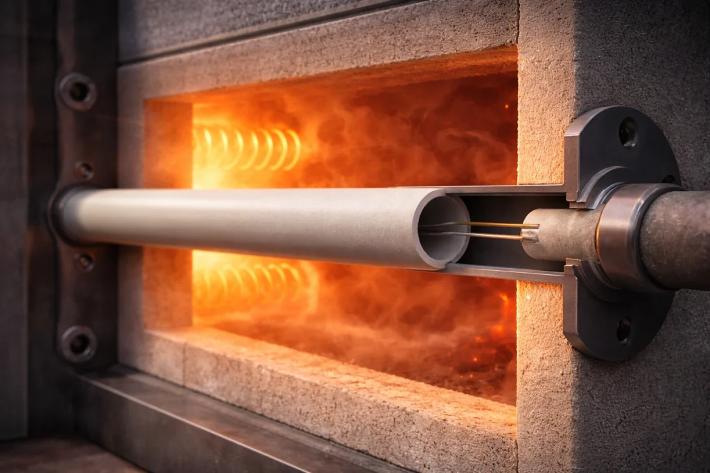
Different Ceramic Thermocouple Protection Tube Material Options
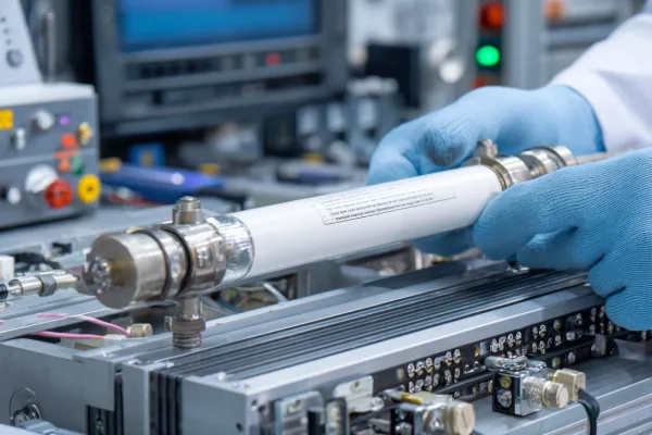
Stable electrical insulation and chemical neutrality in many oxidizing/neutral furnace atmospheres.
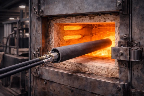
Higher thermal conductivity and robustness for harsh handling and faster thermal profiles
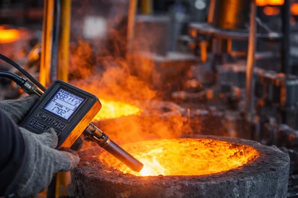
Toughness and thermal-shock resistance for cycling- and vibration-dominated installations.
Thermocouple Protection Tube Material Comparison
| Route | Choose when | Typical use | Boundary |
|---|---|---|---|
| Alumina (high-purity, gas-tight ≈99.7% Al₂O₃) | High temperature + electrical insulation + low drift for precious-metal (R/S/B) thermocouples | Furnaces, heat treatment, gas-tight closed-end sheaths | Thermal-shock sensitive; purity, gas-tightness and closed-end thickness confirmed by drawing |
| Silicon carbide (RBSiC / SSiC) | Abrasion, corrosion and rapid thermal cycling | Severe cycling, erosive/dirty atmospheres | Electrically conductive — needs an inner insulator; confirm gas-tightness |
| Silicon nitride / Sialon | Molten aluminium and non-ferrous melts (LPDC, launder) — non-wetting, strong thermal shock | Immersion temperature measurement in aluminium melts | Lower ceiling in oxidizing air; ask melt chemistry and immersion depth first |
| Zirconia (Mg-PSZ / YSZ) | Thermal insulation, chemical stability, high toughness | Specific insulating / chemically-stable measurement | Low thermal conductivity, higher cost; review thermal shock |
| Quartz | Good thermal-shock resistance, clean surface | Lower-temperature Type-K ranges, clean setups | Lower max temperature; not for highest-temperature noble-metal service |
How to Choose a Ceramic Thermocouple Protection Tube?
Thermocouple ceramic tubes are used to isolate the junction from furnace chemistry and handling while staying stable at high temperature. Unlike general sensor protection tubes that focus on abrasion or corrosion, thermocouple tubes prioritize contamination control and drift reduction.
Key Operating Conditions
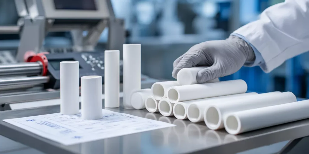
peak temperature, soak duration, ramp rate, and the number of cycles per week.
oxidizing, neutral, vacuum, or mixed; identify vapors (alkali, borates, silica, metal fumes) that can drive drift or tube reaction.
insulation needs, risk of conductive deposits, and cold-end creepage/clearance expectations for signal stability.
OD/ID targets, closed-end thickness, immersion length, straightness, and any dual-bore/insulator needs inside the sheath.
how the tube is supported (cantilever vs guided), clamp compliance, allowance for thermal expansion, and required clearance to avoid binding.
Matching Protection Tubes to Thermocouple Types
Different thermocouple types operate at different temperature ranges and require compatible ceramic materials for protection.
| Thermocouple Type | Max Temp | Recommended Ceramic Tube Material | Typical OD/ID |
|---|---|---|---|
| Type K (Chromel-Alumel) | 1260°C | 99% Al₂O₃, 2-bore,Quartz | OD 6-12mm |
| Type S (Pt-Rh/Pt) | 1600°C | 99.7% Al₂O₃, 2-bore or 4-bore | OD 8-15mm |
| Type R (Pt-Rh/Pt) | 1600°C | 99.7% Al₂O₃, 2-bore or 4-bore | OD 8-15mm |
| Type B (Pt-Rh/Pt-Rh) | 1700°C | 99.7% Al₂O₃, closed-end | OD 10-20mm |
Recommended Materials by Furnace Atmosphere
The furnace atmosphere plays a critical role in selecting the most suitable ceramic material.
| Atmosphere | Recommended Ceramic Tube Material | Notes |
|---|---|---|
| Oxidizing (air, O₂) | 99% or 99.7% Al₂O₃. Quartz | Standard choice, excellent stability |
| Reducing (H₂, CO) | 99.7% Al₂O₃ | Higher purity resists reduction better |
| Vacuum | 99.7% Al₂O₃, gas-tight | Verify porosity specification |
| Molten metal contact | 99.7% Al₂O₃, closed-end. Silicon nitride | Verify compatibility with specific metal |
Standard Thermocouple Protection Tube Sizes (In Stock)
| Type | OD (mm) | ID (mm) | Length (mm) | Purity |
|---|---|---|---|---|
| 2-bore, closed end | 8 | 2×1.5 | 300, 500, 1000 | 99% |
| 2-bore, closed end | 10 | 2×2.0 | 300, 500, 1000 | 99% |
| 4-bore, closed end | 12 | 4×1.5 | 300, 500 | 99.7% |
| Single bore, closed end | 15 | 10 | 500, 1000, 1500 | 99.7% |
Typical Ceramic Tube Builds for Thermocouple Protection
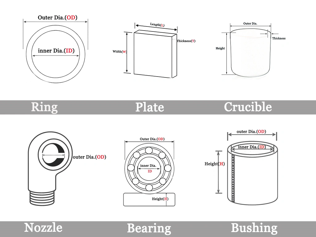
Thermocouple protection tubes are selected by balancing material and configuration. Material affects insulation, contamination control, corrosion resistance, and response, while tube form (open/closed end, multi-bore, flange/thread) controls junction exposure and installation repeatability.
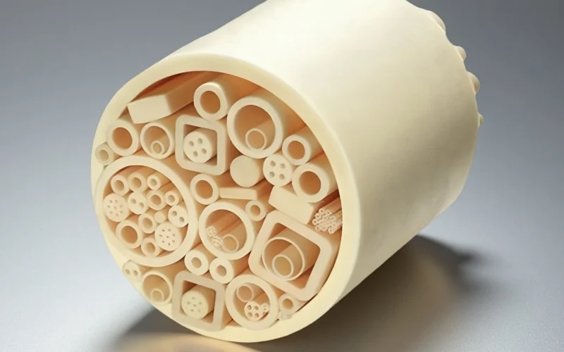
alumina thermocouple protection tube
High electrical insulation and chemical stability for low drift protection.
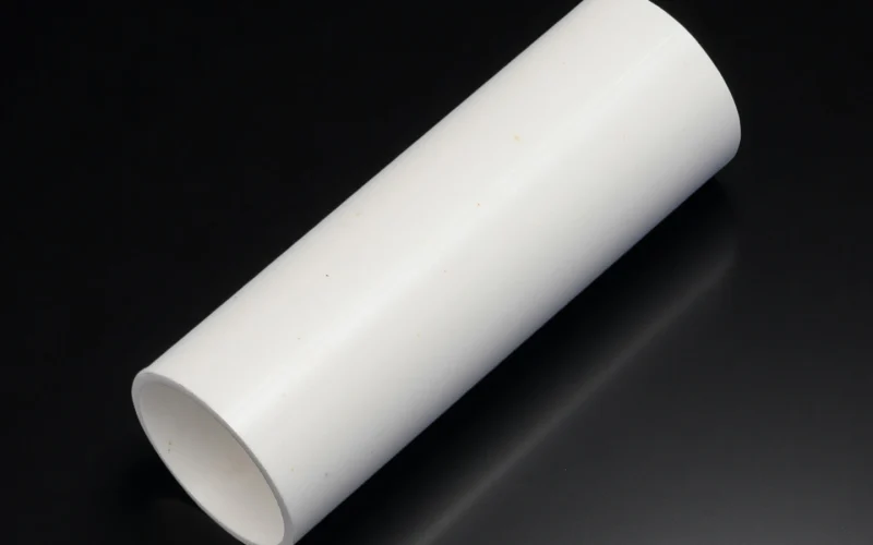
Thermocouple Zirconia Ceramic Tube
High toughness and thermal-shock resistance for cycling stability.
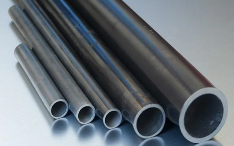
silicon carbide thermocouple protection tube
High thermal conductivity and strength for fast, reliable response.
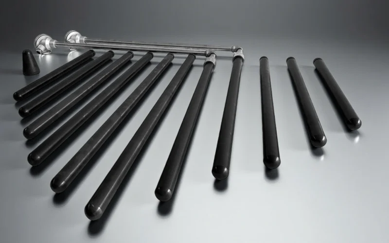
silicon nitride thermocouple protection tube
High electrical insulation and chemical stability for low drift protection.
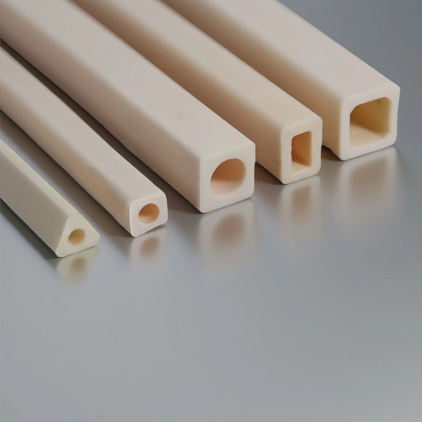
Square ceramic thermocouple protection tubes
For constrained mounts and fixed-orientation requirements. Square profile prevents rotation and improves alignment.

Multi-Bore Ceramic thermocouple protection tubes
For multi-element probes and drift-sensitive control loops. Separated bores improve insulation and reduce cross-talk.
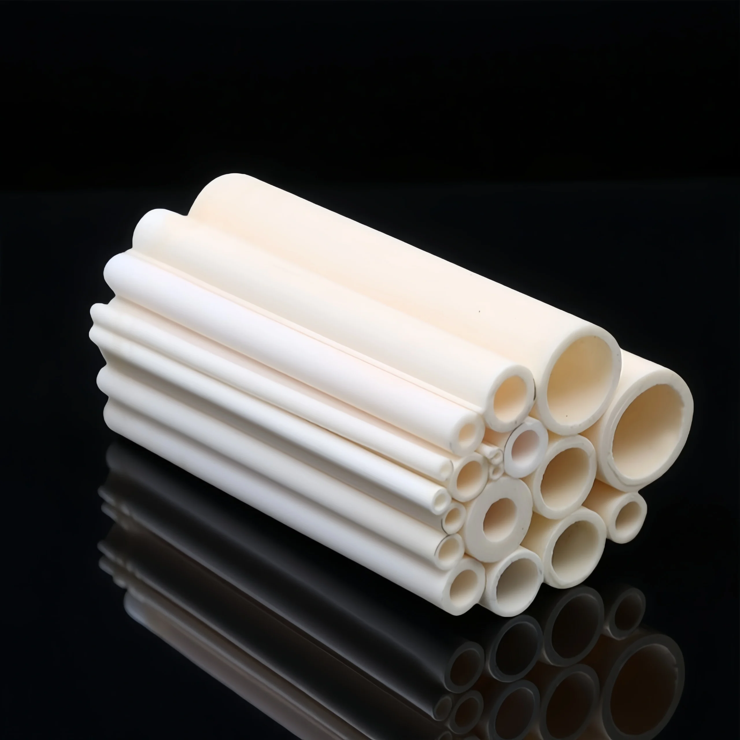
ceramic thermocouple protection tubes, Open Both Ends
For guided furnace installs and frequent probe replacement. Open-through design enables fast insertion and easy maintenance.
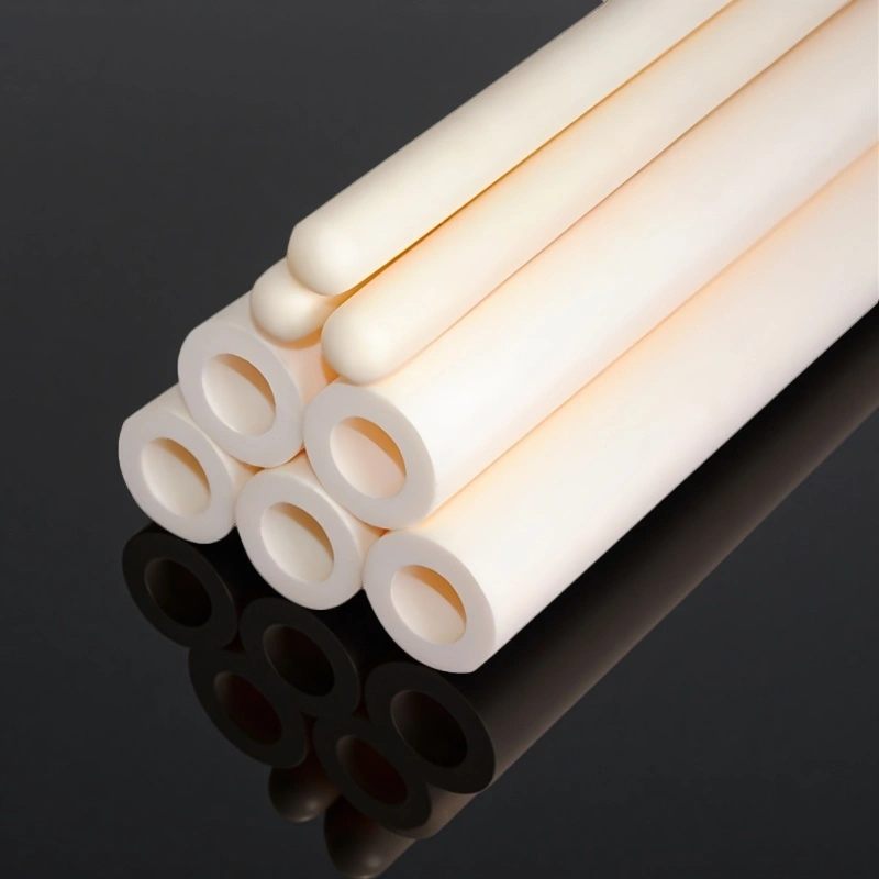
ceramic thermocouple protection tubes, One End Closed
For corrosive atmospheres and drift-sensitive temperature control. Closed tip isolates the hot junction to reduce contamination exposure.
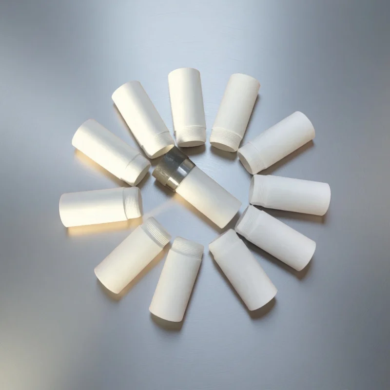
ceramic thermocouple protection tube with threaded
For threaded ports requiring adjustable insertion depth. Threaded mounting locks position with repeatable adjustment.
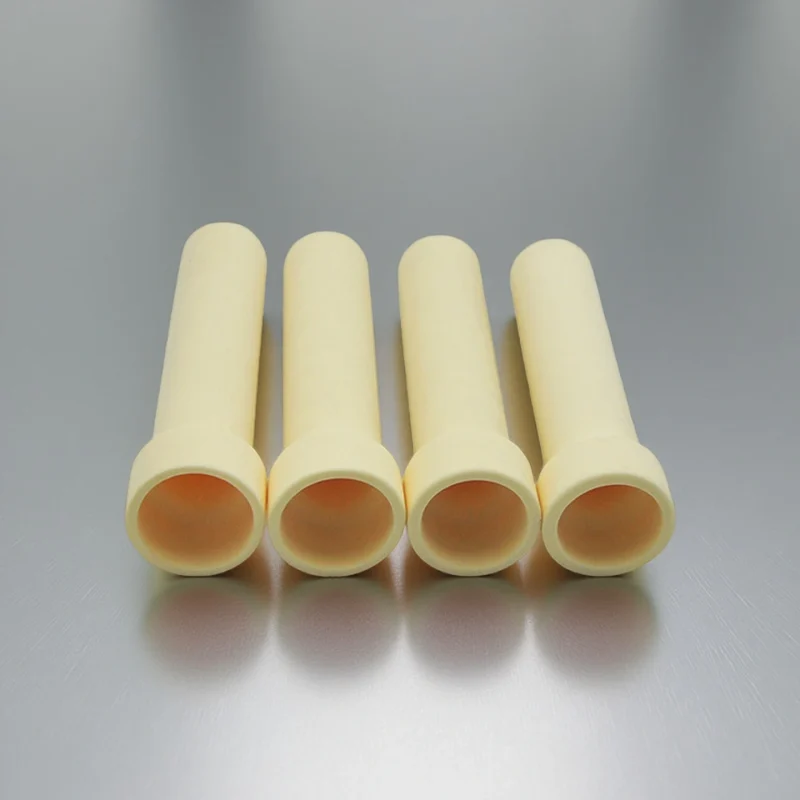
ceramic thermocouple protection tube with flange
For wall penetrations needing fixed depth and sealing. Flange mounting stabilizes position and supports sealing.
Ceramic Thermocouple Protection Tubes Applications
Ceramic thermocouple protection tubes are specified where high temperature, aggressive atmospheres, or thermal cycling would degrade metal sheaths and destabilize temperature measurement.
High-Temperature Furnaces
1.Continuous/batch furnaces in controlled atmospheres
2.Limits scale buildup and measurement drift
3.Common in heat treatment, sintering, and kilns
Chemical Reactors & Process Vessels
1. Reactive gas service with corrosive vapors
2. Isolates the junction from chemical attack
3. Maintains stable readings in
Metallurgical & Foundry Operations
1. High thermal gradients and intermittent exposure
2. Thermal shock, abrasion, and slag resistance
3. Often paired with closed-end or thick-wall tube designs
Power, Energy & Thermal Systems
1. Boilers, reformers, and high-temperature test rigs
2. Stable insulation and protection under thermal cycling
3. Suitable for long insertion lengths and guided mounting
Failure Modes and Mitigation for Ceramic Thermocouple Tubes
Most protection-tube issues are driven by thermal gradients, atmosphere attack, and mounting constraints. Use the table below to match visible symptoms to likely causes and practical design adjustments.
| Symptom | Likely cause | Design / material adjustment | Notes |
|---|---|---|---|
| Hot-end cracking (axial or star cracks) | Thermal shock from fast ramps, door-open events, or cold purge | Increase clearance and add compliant support; consider a more shock-tolerant material/geometry | Avoid rigid clamping near the hot zone |
| Chipping at mouth or support point | Mechanical contact, vibration, misalignment during insertion | Add chamfer/lead-in; improve alignment; use wear-resistant contact region if unavoidable | Many cracks initiate from edge damage |
| Rapid drift / unstable readings | Vapor/deposit contamination of the junction; leakage paths from conductive deposits | Use high-purity alumina for insulation; add sealing/purge control; keep junction isolated from deposits | Drift is often contamination-driven, not sensor failure |
| Surface glazing, pitting, or erosion | Atmosphere chemistry attack, particulate impingement, or slag exposure | Switch to a chemistry-appropriate ceramic (often SiC in harsher exposure); add baffles/shields | Confirm atmosphere species, not only temperature |
| Tube bending or sag over time | Over-temperature soak, long unsupported span, creep under load | Increase wall thickness; shorten unsupported length; add guided support | Treat hot-end temperature as the design limit |
| Premature fracture at mounting interface | Constraint from tight fit, hard set-screws, or thermal expansion mismatch | Use compliant collars; define cold-end clearance; avoid point loading | Mounting design often dominates reliability |
| Seal leakage at wall penetration | Gasket mismatch, flange distortion, or thermal cycling loosening | Use stable sealing stack; control flange flatness; verify thermal expansion allowances | Leaks often appear after cycling, not at install |
| Internal wire shorting (multi-bore) | Deposit bridging, damaged bores, or wire movement under vibration | Specify correct bore spacing; secure wires; keep deposits out via sealing/purge | Improves signal stability in multi-element probes |
Custom Thermocouple Protection Tubes Options
In hot-zone temperature measurement, customization is typically driven by thermal gradients, atmosphere exposure, and mounting constraints, rather than appearance or nominal size.The following options are commonly adjusted to control failure modes such as cracking, drift, or unstable insertion depth.
Custom Options Matrix
| Custom Parameter | Typical Range / Form | Why It Matters in This Application |
|---|---|---|
| Closed-End Thickness | ~1.5–3 mm (typical) | Balances response time and mechanical strength at the hot tip; overly thin ends crack under cycling, overly thick ends slow response. |
| Multi-Bore Configuration | 2-bore / 4-bore / 6-bore | Separates thermocouple wires, improves insulation, and reduces cross-talk or contamination between elements. |
| Flange or Threaded Interface | Designed to match furnace wall or reactor nozzle | Enables repeatable insertion depth, reliable sealing, and controlled axial positioning under thermal expansion. |
| Overall Length & Immersion Depth | Set by hot-zone location | Determines whether the junction sits fully inside the stable temperature zone rather than boundary or gradient regions. |
Installation & Fit-Up Notes
Clearance and mounting compliance are as important as material choice; tight clamping often drives early cracking during ramps.
Closed-end geometry should be matched to ramp rate and cycling severity, not only maximum temperature.
Interface features (flange/thread) are primarily measurement-control features, not mechanical conveniences.
Ceramic Thermocouple Tubes FAQ
- Alumina suits high-temperature, low-drift measurement with precious-metal (R/S/B) thermocouples;
- silicon carbide handles abrasion, corrosion and rapid cycling (it is conductive and usually needs an inner insulator);
- silicon nitride / Sialon is used for molten aluminium and non-ferrous melts because it resists wetting and thermal shock;
- zirconia suits insulating, chemically stable cases.
The right route depends on temperature, atmosphere, melt and failure mode — send your condition for a review.
For molten aluminium (LPDC, launder), silicon nitride / Sialon is usually preferred because it is not readily wetted by the melt and has strong thermal-shock resistance; alumina is generally not the default for melt immersion. Melt chemistry and immersion depth should be confirmed before selecting a route.
Ceramics can be sensitive to thermal shock (especially dense alumina), mullite carries a silica-contamination risk for precious-metal thermocouples, silicon carbide is electrically conductive and often needs an inner insulator, and zirconia has low thermal conductivity and higher cost. Choosing the right material route and confirming geometry, gas-tightness and mounting reduces these trade-offs.
It can be reviewed from an old-part photo and the failure reason. A replacement must match OD/ID, length and the mounting interface, and the material route should match the original working condition. We do not promise a drop-in replacement before a drawing and interface review.
It depends on the material route and atmosphere — as typical references, high-purity alumina is used to around 1600–1800°C in air, mullite around 1500–1700°C, silicon carbide around 1400–1650°C in air, and silicon nitride/Sialon around 1200–1400°C in aluminium immersion. These are typical values, not guaranteed continuous-use ratings; the usable limit is confirmed by engineering review for your condition.
A drawing or old-part photo; OD/ID/length and tolerance; closed/open end and bore count; fitting (flange/thread/collar); thermocouple type; temperature and atmosphere; molten metal or furnace environment and immersion depth; quantity; and any certificate requirement.
Thermocouple Protection Tube RFQ Checklist
Include these with your drawing or old-part photo so engineering review is fast and the quote is accurate:
- Material route — alumina, SiC, silicon nitride / Sialon, zirconia, or quartz
- Dimensions & tolerance — OD × ID × length, wall / closed-end thickness, and straightness tolerance.
- Structure & interface — closed or open end, bore count (single / twin / multi-bore), and fitting (flange / thread / collar / head).
- Thermocouple type — K / N / R / S / B.
- Operating conditions — temperature profile, atmosphere and vapor/deposit species, molten metal & immersion depth, and response-time sensitivity.
- Quantity & stage — prototype / small batch / repeat OEM.
A drawing or an old part alone is enough to get started; the rest is confirmed during engineering review.
*Our team will answer your inquiries within 24 hours.
*Your information will be kept strictly confidential.
info@adcerax.com
Tel:+86-0731-84428843
WhatsApp:+86 19311583352
Within 24 hours