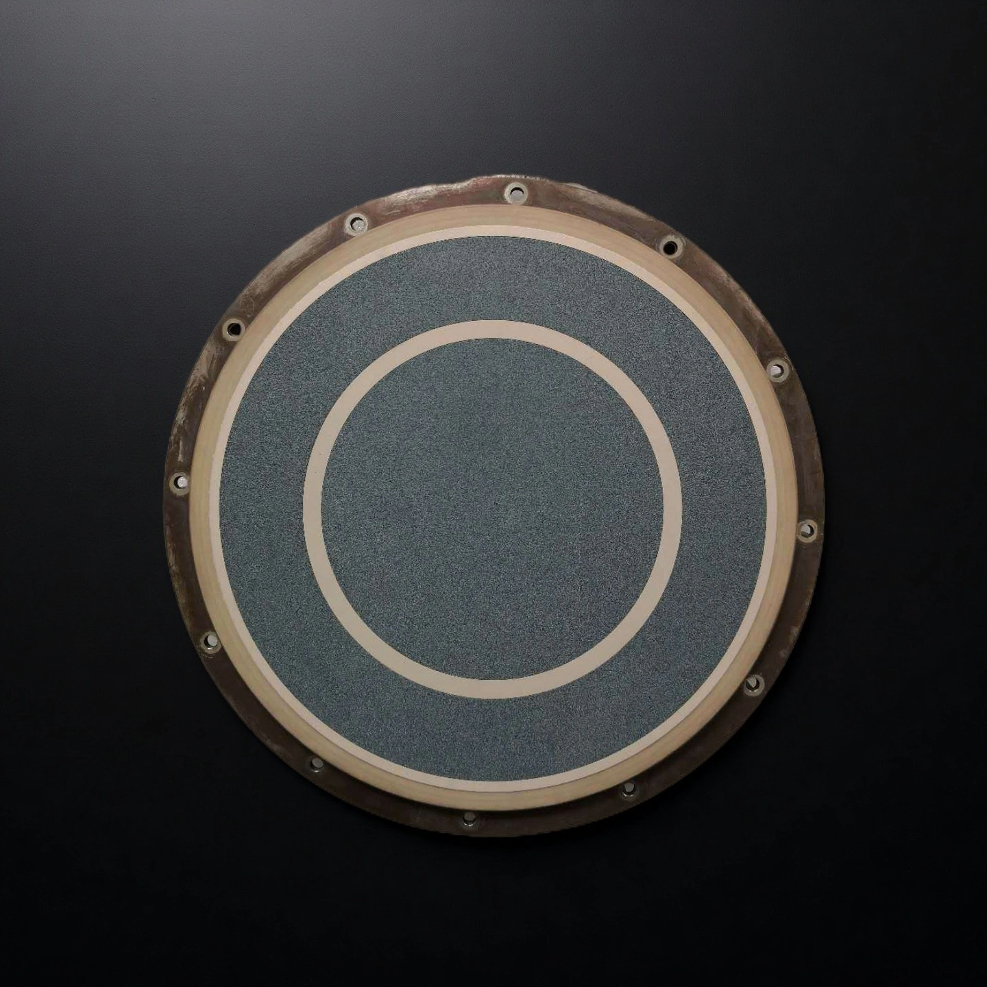
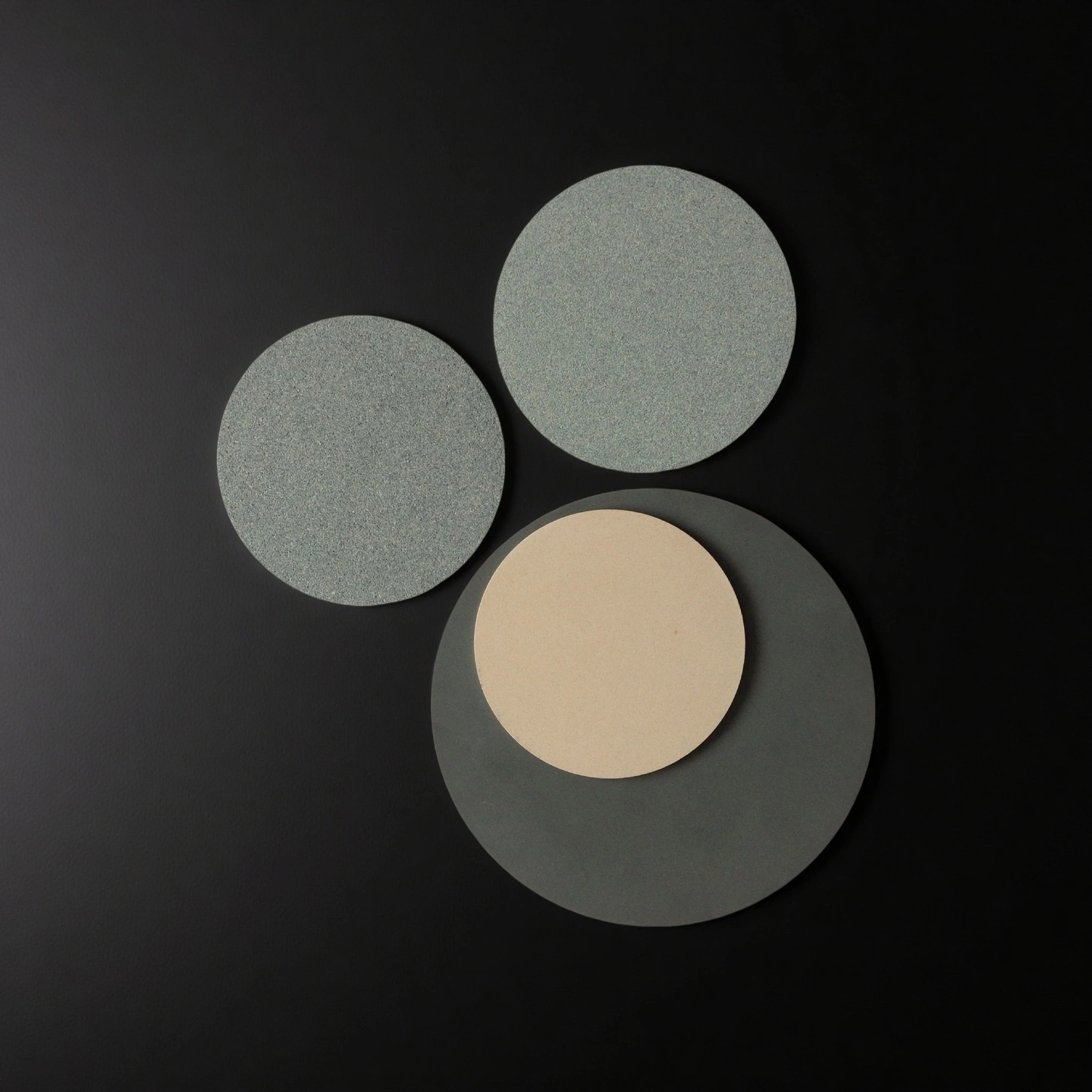
What Is a Porous Alumina Vacuum Chuck?
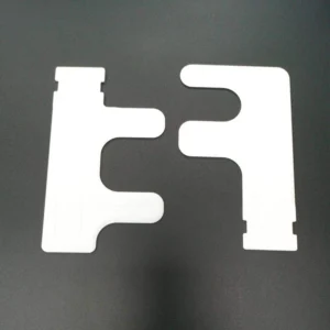
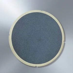
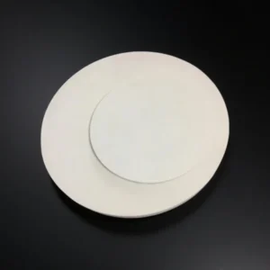
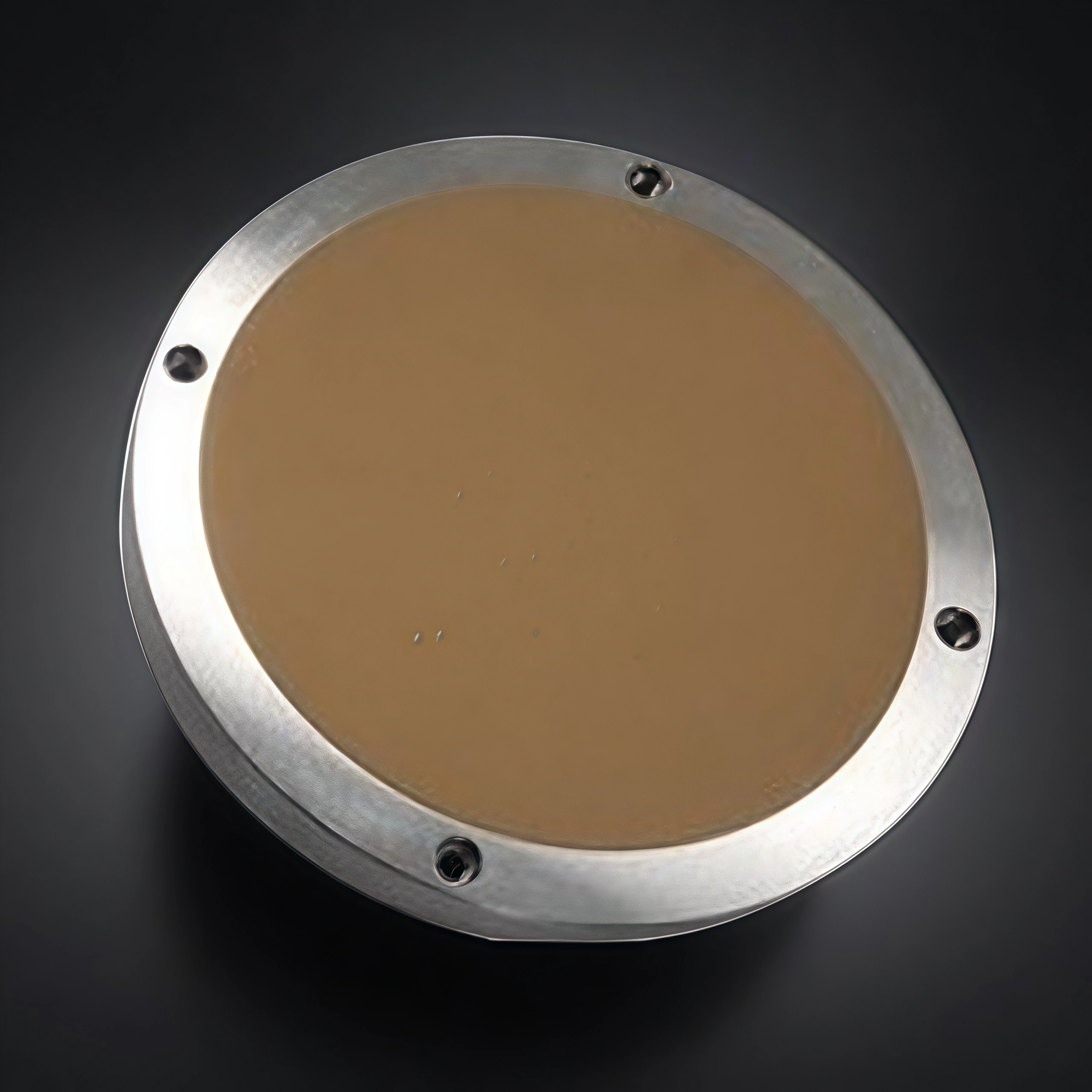
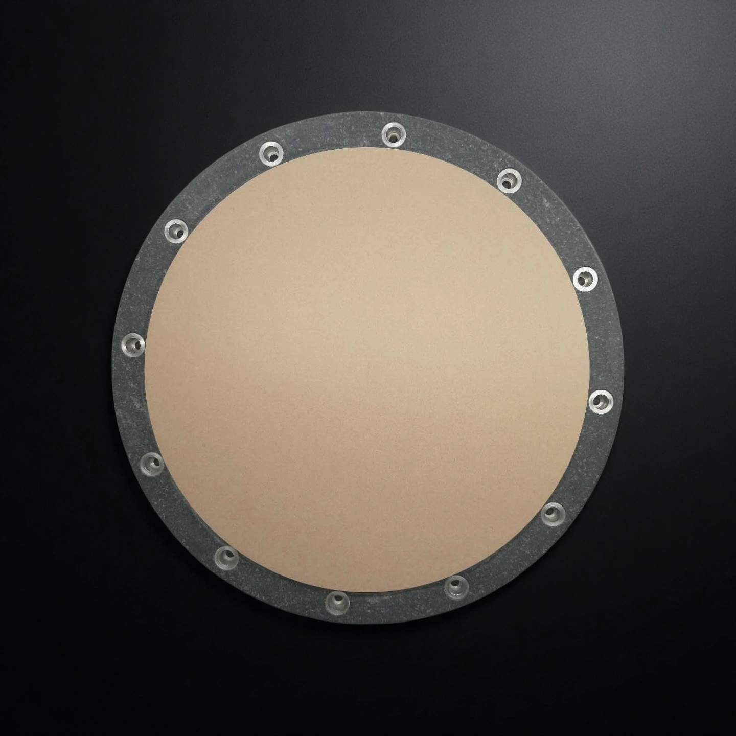
A porous alumina vacuum chuck is a precision workholding component that distributes vacuum airflow through a porous ceramic working surface. Compared with drilled-hole or groove-type chuck designs, the porous surface can help limit localized suction peaks and provide more even support for thin, flat or fragile workpieces.
Important configuration variables include pore size, porosity, effective holding area, surface flatness, finish, vacuum-zone layout, port position, back-chamber design and mounting geometry. Their final combination depends on the workpiece, vacuum source, process step, inspection method, cleaning requirements and equipment interface.
Typical application areas include thin-glass inspection, optical-component handling, solar-cell transfer, film handling, R&D fixtures and selected wafer-handling processes.
Engineering Benefits of Porous Alumina Vacuum Chucks
The engineering value of a porous alumina vacuum chuck depends on how the porous working layer, airflow, flatness, vacuum zones and equipment interface are specified as one system.
- More Even Vacuum Distribution
The porous working surface helps distribute airflow across the effective holding area and limit localized suction peaks. - Application-Based Pore Selection
Pore size can be reviewed against holding force, airflow, clogging risk, cleaning method and workpiece sensitivity. - Flatness-Controlled Working Surface
Flatness, effective area, datum and inspection method can be defined by drawing for inspection, alignment and transfer processes. - Material Color and Surface Finish Options
White or black alumina surfaces with fine-ground or polished finishes can be reviewed according to optical contrast, glare control and contact requirements. - Custom Vacuum and Mounting Features
Vacuum zones, datum holes, chamfers, ports and mounting interfaces can be reviewed against the equipment layout and process flow.
Actual holding performance, flatness response and marking behavior depend on pore size, vacuum level, workpiece material and geometry, and are confirmed for each application.
Porous Alumina Vacuum Chuck Properties
| Property | Unit | 96% Al₂O₃ | 99% Al₂O₃ | 99.5% Al₂O₃ | 99.6% Al₂O₃ | 99.7% Al₂O₃ | 99.8% Al₂O₃ | 99.9% Al₂O₃ | 99.99% Al₂O₃ |
| Alumina content | % | 96 | 99 | 99.5 | 99.6 | 99.7 | 99.8 | 99.9 | 99.99 |
| Density | g/cm³ | 3.6-3.75 | 3.83 | 3.89 | 3.91 | 3.92 | 3.93 | 3.94 | 3.98 |
| Color | – | white | Ivory | Ivory | Ivory | Ivory | Ivory | Ivory | Ivory |
| Water absorption | % | 0 | 0 | – | 0 | 0 | 0 | 0 | 0 |
| Young’s modulus (Elastic modulus) | GPa | 300 | 350 | 375 | 356 | 357 | 358 | 359 | 362 |
| Shear modulus | GPa | – | – | 152 | – | – | – | – | – |
| Bulk modulus | GPa | – | – | 228 | – | – | – | – | – |
| Poisson’s ratio | – | – | – | 0.22 | – | – | – | – | – |
| Compressive strength | MPa | 1910 | 2210 | 2500 | 2552 | 2554 | 2556 | 2558 | 2570 |
| Flexural strength | MPa | 260 | 300 | 340 | 345 | 346 | 347 | 348 | 365 |
| Fracture toughness | MPa·m¹ᐟ² | – | – | 4 | – | – | – | – | – |
| Hardness | GPa | 14.5 | 17 | 17 | 23 | 24 | 25 | 26 | 30 |
| Thermal conductivity | W/m·K | 20 | 31 | 31 | 31-33 | 31-33 | 31-33 | 31-35 | 31-35 |
| Thermal shock resistance ΔT | °C | – | – | – | 222 | 223 | 224 | 225 | 228 |
| Maximum use temperature (no load) | °C | 1450 | 1680 | ≤1750 | 1755 | 1760 | 1765 | 1770 | 1800 |
| Coefficient of thermal expansion | 10⁻⁶/°C | 7.6 | 7.6 | 7.6 | 7.6 | 7.5 | 7.5 | 7.4 | 7.4 |
| Volume resistivity | Ω·cm | >1×10¹⁴ | >1×10¹⁴ | >1×10¹⁴ | >1×10¹⁴ | >1×10¹⁴ | >1×10¹⁴ | >1×10¹⁴ | >1×10¹⁴ |
| Dielectric constant (relative permittivity) | – | 9.2 | 9.5 | 9.8 | 9.83 | 9.84 | 9.85 | 9.86 | 9.92 |
| Dielectric strength | kV/mm | 15 | 19 | 16.9 | 23.2 | 23.4 | 23.6 | 23.8 | 24 |
| Dissipation factor (loss factor @ 1 kHz) | – | – | – | 0.0002 | – | – | – | – | – |
Reference Sizes for Porous Alumina Vacuum Chucks
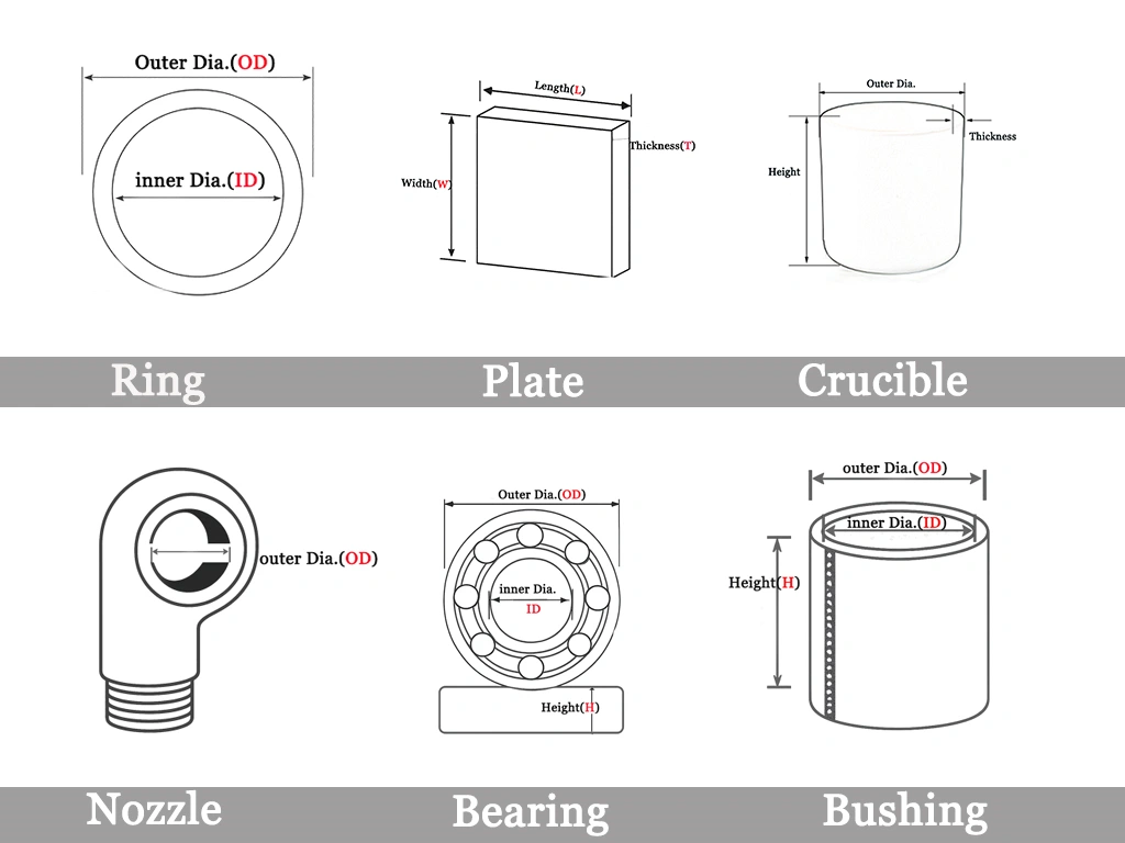
The following sizes are reference options for preliminary selection. Final availability, dimensional tolerance, surface flatness, pore size, base material and port layout should be confirmed according to the drawing, workpiece size, vacuum system and required quantity.
Type 1: Square Microporous Alumina Vacuum Chuck
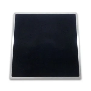
| Square Microporous Alumina Vacuum Chuck | ||||
| Item NO. | Length (mm) | Width (mm) | Thickness (mm) | Material |
| AT-YHL-XP001 | 305 | 305 | 14 | 316 stainless steel + microporous ceramic (brown) |
| AT-YHL-XP002 | 305 | 305 | 14 | 316 stainless steel + microporous ceramic (brown) |
| AT-YHL-XP003 | 420 | 275 | 20 | Aluminum alloy + microporous ceramic |
| AT-YHL-XP004 | 450 | 200 | 20 | SKD61 + porous ceramic |
| AT-YHL-XP005 | 520 | 520 | 20 | Aluminum alloy + microporous ceramic |
Type 2: Round Microporous Alumina Vacuum Chuck
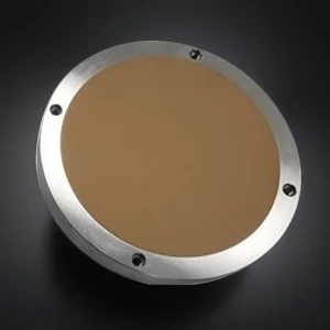
| Round Microporous Alumina Vacuum Chuck | |||
| Item NO. | Diameter (mm) | Thickness (mm) | Material |
| AT-YHL-XP006 | 174 | 10 | 316 stainless steel + microporous ceramic |
| AT-YHL-XP007 | 220 | 35 | Only alumina ceramic |
| AT-YHL-XP008 | 230 | 16 | 316 stainless steel + microporous ceramic |
| AT-YHL-XP009 | 239 | 12 | Aluminum alloy + microporous ceramic |
| AT-YHL-XP010 | 240 | 12 | 316 stainless steel + microporous ceramic |
| AT-YHL-XP011 | 286 | 20 | Only alumina ceramic |
| AT-YHL-XP012 | 320 | 16 | 316 stainless steel + microporous ceramic |
| AT-YHL-XP013 | 325 | 12 | Aluminum alloy + microporous ceramic |
Packaging Requirements for Porous Alumina Vacuum Chucks
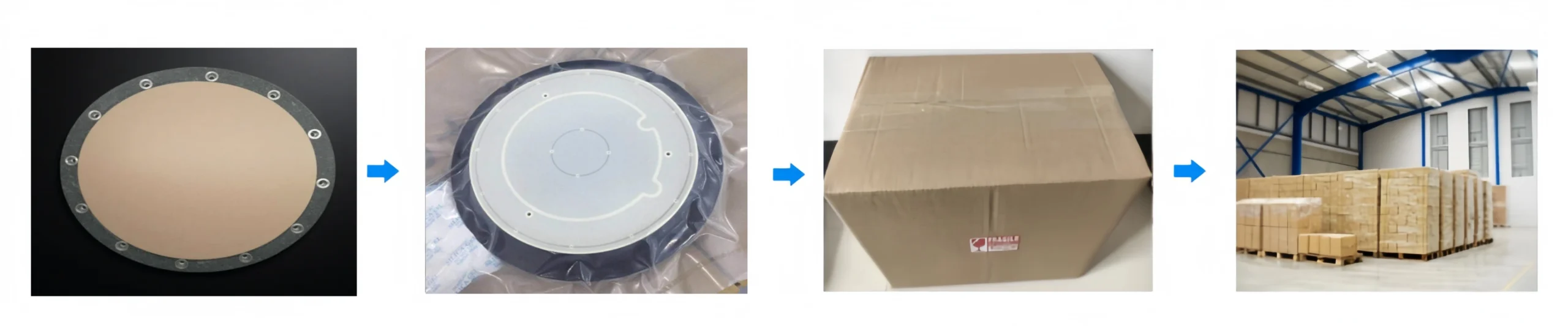
Packaging requirements are reviewed according to the chuck size, weight, porous working surface, edge features and shipping method. The final protective wrapping, cushioning and outer packaging are confirmed for each order.