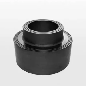
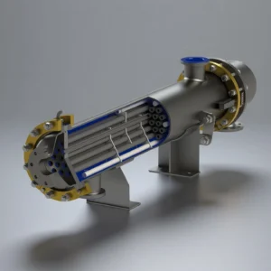
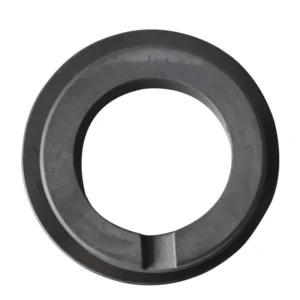
What Is a Silicon Carbide Heat Exchange Block?
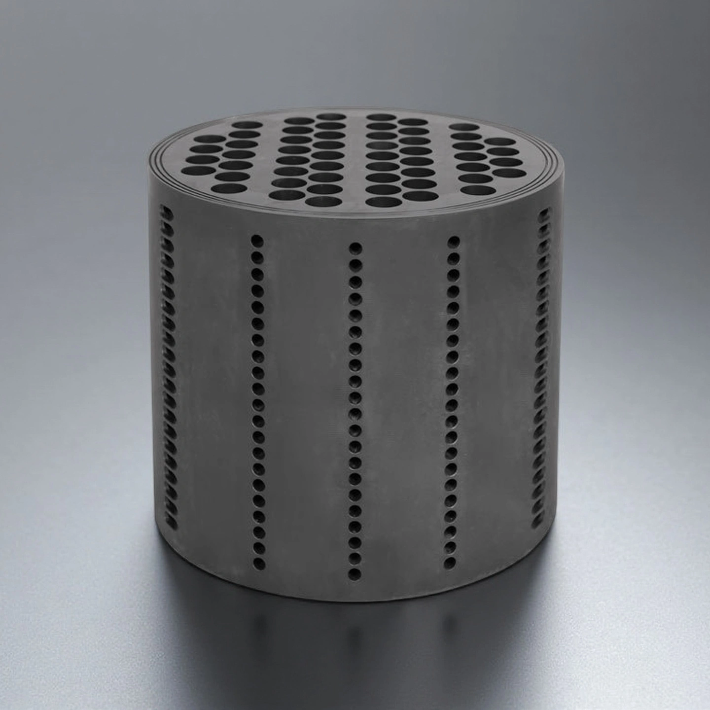
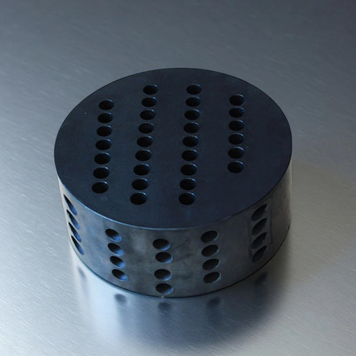
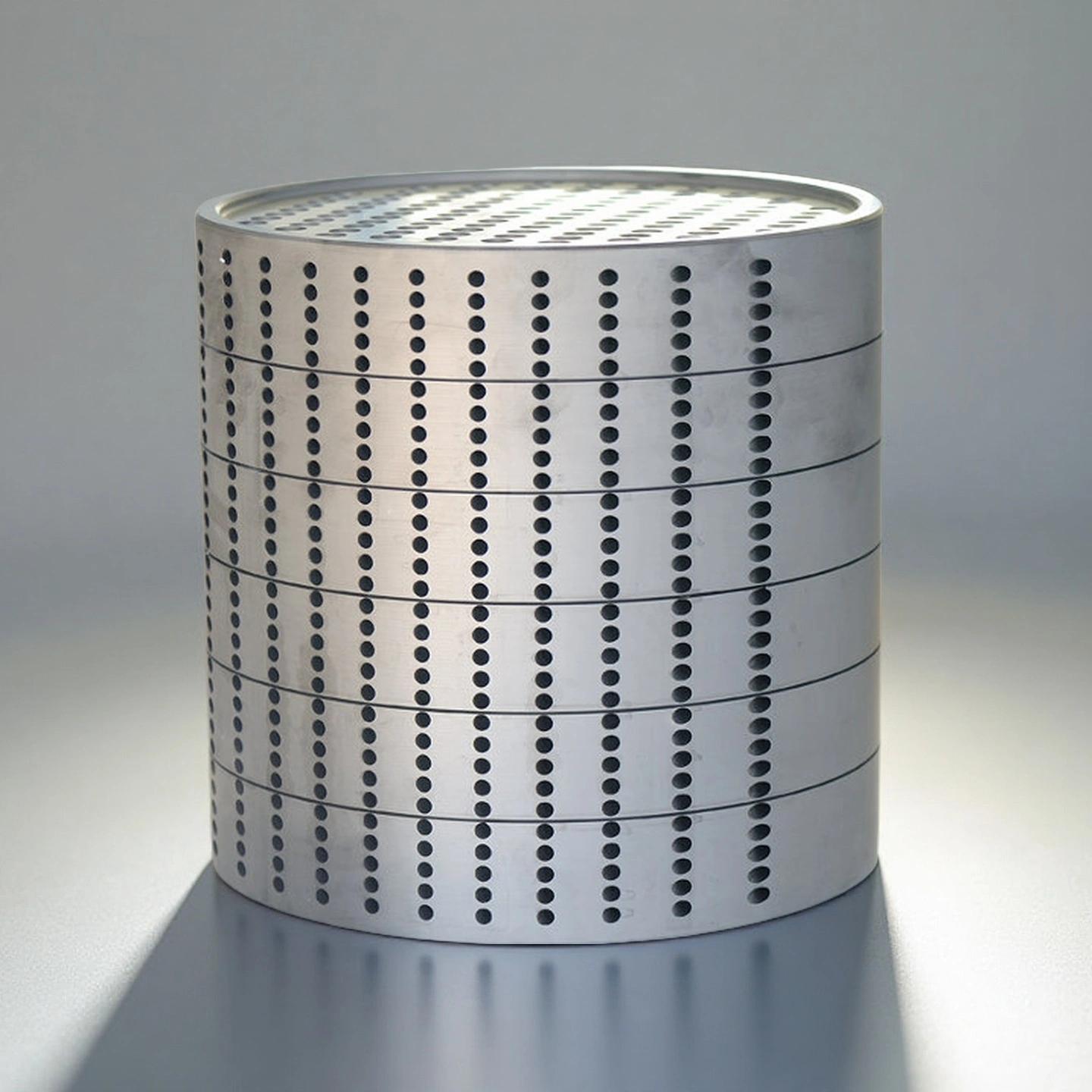
A silicon carbide heat exchange block is a dense SiC ceramic block used as the heat-transfer core in block-type heat exchangers. The block is typically designed with process and service channels so heat can transfer through the silicon carbide wall while keeping the two fluids separated.
Compared with graphite or metal heat-transfer components, silicon carbide is selected when the system requires stronger corrosion resistance, higher hardness, better thermal stability and cleaner operation in aggressive chemical or thermal process environments.
Why Silicon Carbide Is Used for Heat Exchange Blocks
- Corrosion resistance for aggressive fluids: Silicon carbide is suitable for many acidic, alkaline and oxidizing media where metal alloys or graphite may face corrosion, erosion or contamination risk.
- Stable heat-transfer behavior: The material’s high thermal conductivity helps support efficient heat movement across the block wall in cooling, condensation, evaporation and heat-recovery duties.
- Dimensional stability under thermal load: Low thermal expansion helps reduce geometry change when the block is exposed to repeated heating and cooling cycles.
- Wear resistance in high-velocity flow: The hard SiC surface helps reduce channel wear when the process stream contains particles or moves at higher velocity.
- Cleaner operation than graphite in selected systems: Dense SiC ceramic can help reduce contamination risk in processes where carbon shedding, metal ion release or corrosion by-products are a concern.
Technical Specifications of Silicon Carbide Heat Exchange Block
The following values are typical reference data for silicon carbide ceramic and should be reviewed together with the final material grade, process media, operating temperature, pressure condition and exchanger design.
| Parameter |
Typical Reference Data |
Engineering Relevance |
| Material Composition |
High-purity SiC ceramic |
This determines corrosion resistance, thermal stability and cleanliness in process media. |
| Thermal Conductivity |
120–180 W/m·K |
This affects heat-transfer efficiency and exchanger sizing. |
| Thermal Expansion Coefficient |
4.0–4.5 ×10⁻⁶/K |
Lower expansion helps reduce thermal stress during temperature cycling. |
| Density |
3.10–3.15 g/cm³ |
Higher density supports structural stability and lower open porosity. |
| Open Porosity |
<0.1% |
Lower porosity helps reduce fluid penetration and contamination risk. |
| Flexural Strength |
350–450 MPa |
This affects resistance to mechanical stress during handling and installation. |
| Compressive Strength |
>2000 MPa |
This supports load-bearing stability inside block assemblies. |
| Hardness |
22–25 GPa |
This helps resist abrasion from high-velocity or particle-containing process streams. |
| Thermal Shock Resistance |
ΔT ≥250°C |
This helps evaluate whether the block can tolerate process temperature changes. |
| Chemical Compatibility |
Strong acids, alkalis and oxidizing media, subject to application review |
Compatibility should be confirmed against actual concentration, temperature and cleaning method. |
Dimensions of Silicon Carbide Heat Exchange Block
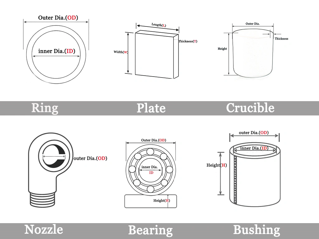
ADCERAX supports custom silicon carbide heat exchange blocks based on drawings, samples or exchanger assembly requirements. Instead of using one fixed standard size, the block geometry is reviewed according to process duty, flow direction, channel arrangement, sealing method and installation space.
For faster engineering review, please provide the block diameter or outer profile, height, channel diameter, channel quantity, channel pitch, process media, service media, working temperature, pressure range and cleaning method.
|
SiC Heat Exchanger |
|
Item No. |
Diameter(mm) |
Height (mm) |
|
AT-THG-HRK2001 |
Customize |
Packaging of the Silicon Carbide Heat Exchange Block
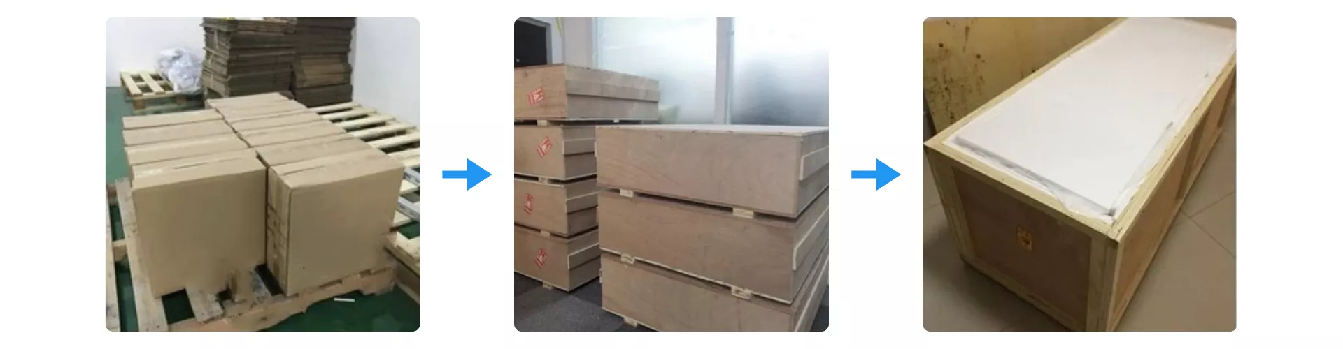
Silicon Carbide Heat Exchange Block units are protected with reinforced carton layers and vibration-resistant internal padding before being secured in export-grade wooden crates. Each crate is stabilized on pallets to prevent impact during loading and long-distance transport. Moisture-barrier lining is added to maintain material integrity throughout international shipping and warehouse handling.
Applications in Corrosive and Thermal Process Systems
The following notes help reduce handling, installation and start-up risks for silicon carbide heat exchange blocks. Final operating procedures should follow the exchanger design, gasket system, plant safety rules and actual process conditions.
-
Chemical Cooling and Reaction Temperature Control
Silicon carbide heat exchange blocks are used in chemical cooling systems where corrosive fluids, reaction heat and temperature stability must be controlled at the same time. In chlorination, sulfonation and acid-processing lines, the SiC block helps provide a corrosion-resistant heat-transfer surface while reducing the risk of channel erosion or material contamination.
-
Condensation and Evaporation of Corrosive Media
For condensation, evaporation and absorption processes, the block structure allows heat to transfer through the SiC wall while keeping process and service fluids separated. This is useful when conventional metal heat exchangers may face corrosion, oxidation or frequent maintenance in aggressive media.
-
Fine Chemical and Selected Clean Process Lines
In fine chemical and selected clean process systems, dense SiC ceramic can help reduce the risk of metal contamination and surface degradation. Application suitability should be reviewed based on media composition, cleaning protocol, operating temperature and equipment validation requirements.
-
High-Temperature Heat Recovery Systems
Silicon carbide heat exchange blocks may also be used in heat-recovery systems where thermal cycling, hot gas exposure or corrosive exhaust streams create challenges for metallic heat-transfer components. The material’s thermal stability and low expansion support more stable geometry under repeated heating and cooling conditions.
-
Replacement of Graphite or Metal Heat Exchanger Components
When graphite blocks face erosion, carbon shedding or mechanical fragility, and metal exchangers face corrosion or contamination risk, silicon carbide can be evaluated as an upgrade material. The final selection should be based on chemical compatibility, pressure conditions, cleaning method, thermal duty and assembly design.
Usage Notes for Silicon Carbide Heat Exchange Blocks
The Silicon Carbide Heat Exchange Block from ADCERAX® requires proper handling, installation and operational practices to maintain stable heat-transfer performance in corrosive, high-temperature and continuous-flow environments. This guide summarizes the essential precautions and usage recommendations that help ensure long-term reliability and predictable thermal behavior in industrial systems.
-
Installation
Before installation, check whether the block dimensions, channel direction and sealing faces match the exchanger assembly. The block should be supported evenly during handling to avoid edge impact or point loading. Sealing surfaces should remain clean before final assembly.
-
Start-Up
During start-up, increase temperature and flow gradually according to the equipment procedure. Sudden pressure shock, uneven tightening or rapid thermal changes should be avoided because ceramic components are sensitive to mechanical impact and concentrated stress.
-
Cleaning
Cleaning methods should be selected according to the process media, deposit type and system compatibility. After cleaning, channels should be inspected for blockage, residue or contamination before the exchanger returns to full operation.
-
Storage and Handling Precautions
1. Store blocks in dry, vibration-free environments
Moisture fluctuations may compromise packaging integrity or introduce contaminants. A stable, low-humidity environment extends the service readiness of stored components. Wooden crates with moisture-barrier lining are preferred for long-term storage.
2. Avoid stacking without structural support
Direct stacking may apply unintended compressive loads and risk micro-fractures at the edges. Use pallet structures or spacing frames to distribute weight. Handling personnel should follow non-impact lifting protocols at all times.
3. Protect channel entrances from dust intrusion
Seal openings with protective caps or film to prevent airborne contaminants from settling inside. When blocks must be moved frequently, ensure that protective layers remain intact. Maintaining clean channels ensures stable flow distribution when the unit enters service.