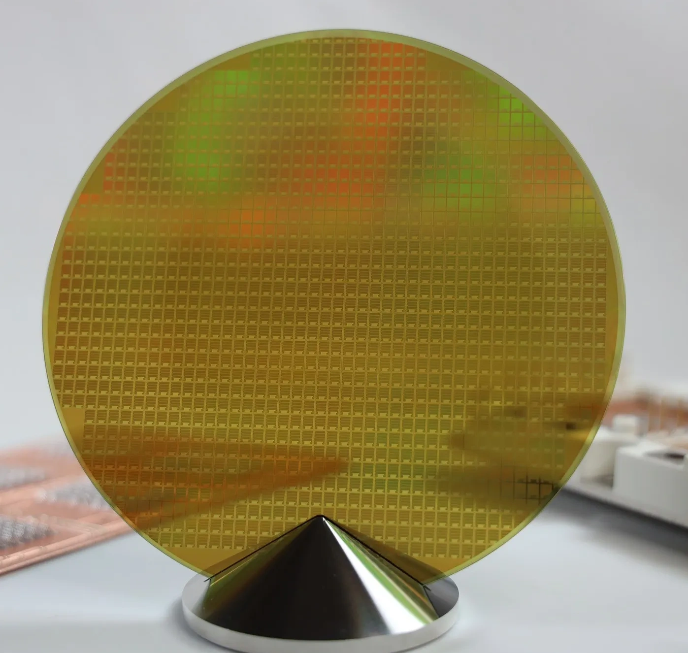
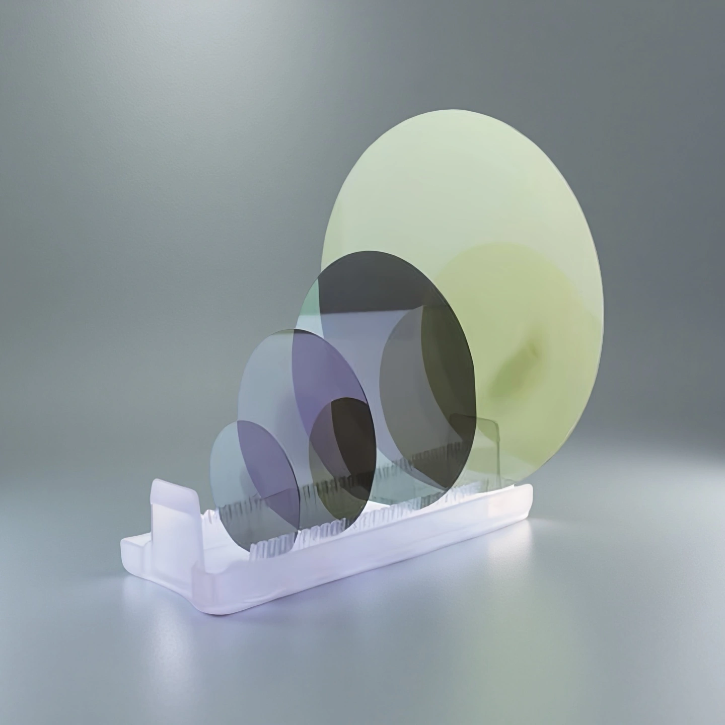
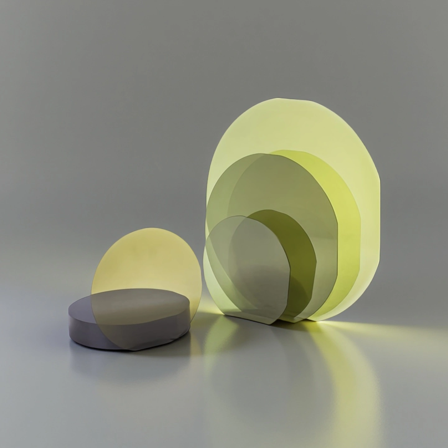
What Is a Silicon Carbide Ceramic Wafer?
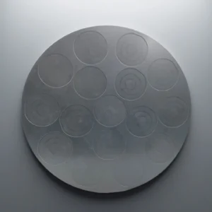
A silicon carbide ceramic wafer is a flat SiC component used where thermal conductivity, hardness, wear resistance, chemical stability and dimensional control must work together. Compared with many oxide ceramic materials, SiC provides stronger thermal shock resistance and better heat-spreading behavior, making it useful in thermal platforms, precision ceramic fixtures, test substrates, support discs and custom engineering assemblies.
For semiconductor-related projects, ADCERAX can review the application conditions and required specifications before quotation. If the project requires semiconductor-grade crystal quality, epi-ready CMP surfaces, exact defect density or wafer-contact process compatibility, these requirements should be clearly stated during RFQ review.
Key Engineering Advantages of Silicon Carbide Wafer
Silicon carbide ceramic wafers are selected when the part must remain stable under heat, mechanical stress, surface wear or chemically demanding environments. The material provides a combination of high hardness, good thermal conductivity and low thermal expansion, helping the wafer maintain shape and surface integrity during precision handling or thermal exposure.
For engineering buyers, the most important value is not only the material name, but whether the wafer geometry, surface condition and inspection requirements match the actual process. ADCERAX supports specification review before production so that diameter, thickness, flatness, finish and packaging method can be aligned with the intended application.
Key Silicon Carbide Wafer Parameters for Engineering Review
The following values are reference points for SiC wafer specification review. Final values, inspection method and availability should be confirmed according to wafer grade, supplier data sheet and project requirement.
| Property |
Specification |
Why It Matters for Application |
| Material System |
4H-SiC / 6H-SiC |
The crystal type affects electrical behavior, thermal stability and suitability for power, RF or research-related applications. |
| Bandgap Energy |
3.23 eV |
A wide bandgap supports high-voltage and high-temperature operating conditions compared with conventional silicon materials. |
| Critical Breakdown Field |
~2.8 MV/cm |
A higher breakdown field helps support compact device designs where voltage resistance is a key requirement. |
| Thermal Conductivity |
~4.9 W/cm·K |
Strong thermal conductivity helps transfer heat away from the working surface and supports better thermal management. |
| Electron Saturation Velocity |
2×10⁷ cm/s |
High electron velocity supports fast response behavior in applications where switching speed or signal performance matters. |
| Intrinsic Temperature Limit |
>600 °C |
This indicates the material’s ability to remain stable in high-temperature environments before intrinsic carrier effects become significant. |
| Micropipe Density |
<0.1 cm⁻² |
Lower micropipe density helps reduce crystal-related defects that may affect wafer consistency and downstream processing yield. |
| Basal-Plane Dislocation Density |
few ×10³ cm⁻² |
Lower dislocation density supports better crystal quality and helps reduce risks in demanding wafer-level applications. |
| Epitaxial Thickness Uniformity |
<2% deviation |
Uniform epitaxial thickness helps maintain consistent electrical and processing behavior across the wafer surface. |
| Doping Uniformity |
High in-plane stability |
Stable doping distribution supports more predictable electrical performance across different wafer areas. |
| Surface Roughness (SSP/DSP) |
Low-RMS polished finish |
A smoother surface is important for contact quality, inspection, coating, bonding or further precision processing. |
| Crystal Orientation Stability |
High-precision (0001) structure |
Stable crystal orientation helps ensure predictable material behavior during machining, inspection or device-related processing. |
| Electrical Type |
N-type / Semi-insulating |
Electrical type selection determines whether the wafer is suitable for conductive, semi-insulating or RF-related application needs. |
| Thermal Expansion Behavior |
SiC-consistent CTE stability |
Controlled thermal expansion helps reduce stress, warping and mismatch risks during heating, cooling or assembly. |
Silicon Carbide Wafer Available Sizes
ADCERAX can review silicon carbide ceramic wafers and SiC substrate blanks according to customer drawings, samples or application requirements. Standard inquiry information should include diameter, thickness, quantity, surface finish, edge condition, tolerance requirements and the working environment.
Packaging of Silicon Carbide Wafer
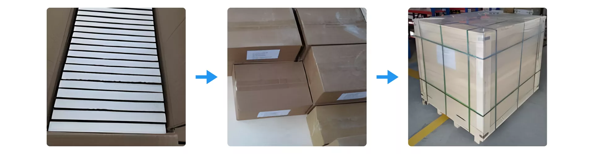
Silicon carbide ceramic wafers are packed with surface separation, cushioning and reinforced outer protection to help reduce scratches, edge chips and vibration damage during shipment. For polished or precision-ground wafers, individual separation and edge protection can be arranged.
Typical Applications for Silicon Carbide Ceramic Wafers
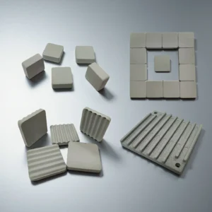
Silicon carbide ceramic wafers are used when a flat ceramic component must combine thermal stability, high hardness, wear resistance and dimensional control. Instead of serving only as a semiconductor material, SiC wafers can also be designed as engineering blanks, precision discs, thermal support parts and equipment interface components.
ADCERAX focuses on application-based review. Before production, the wafer geometry, thickness, surface finish, edge condition and inspection requirements can be evaluated according to the customer’s drawing, fixture design or operating environment.
-
Thermal Management and Heat-Spreading Platforms
Silicon carbide ceramic wafers can be used as flat heat-spreading components in assemblies where heat must be transferred away from a contact surface while maintaining dimensional stability. The material’s thermal conductivity and low thermal expansion help reduce deformation risks during heating and cooling cycles.
This makes SiC wafer blanks suitable for thermal test platforms, ceramic heat-transfer interfaces, high-temperature support plates and custom thermal management assemblies where metal parts may suffer from oxidation, softening or surface wear.
-
Precision Fixtures and Positioning Components
In precision equipment, a wafer-shaped SiC ceramic part can function as a support disc, locating plate, spacer or positioning surface. The high hardness and wear resistance of silicon carbide help reduce surface damage caused by repeated contact, sliding or clamping.
For fixture designers, the most important factors are flatness, parallelism, edge strength and surface finish. ADCERAX can review these details before quotation so the wafer is not only made to size, but also matched to the way it will be installed and handled.
-
Laboratory, R&D and Material Evaluation
Custom SiC wafer blanks are often used in laboratory testing, prototype development and material evaluation projects. Engineers may use them as test discs, thermal trial samples, carrier blanks or reference ceramic parts before moving to a more complex component design.
This application is suitable for customers who need small-batch SiC ceramic wafers for evaluation, but do not yet have a finalized production drawing. ADCERAX can review diameter, thickness, surface condition and machining feasibility based on the trial purpose.
-
Equipment Support and Interface Components
Silicon carbide ceramic wafers can also be used as equipment support components where a flat, rigid and chemically stable ceramic surface is required. Typical forms include discs, carrier plates, spacer wafers, interface pads and custom support blanks.
In these applications, the wafer must fit the surrounding mechanical structure. Hole positions, grooves, chamfers, edge clearance and mounting requirements should be reviewed carefully to reduce machining risk and improve assembly compatibility.
-
Semiconductor Equipment Hardware and Wafer-Handling Related Parts
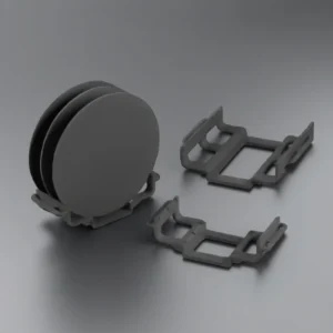
For semiconductor-related equipment, SiC ceramic wafers may be reviewed as hardware parts, fixture components, support discs, dummy wafer forms or wafer-handling related ceramic blanks. These applications require careful confirmation because dimensional accuracy, surface condition, cleanliness and inspection requirements may be stricter than general industrial ceramic parts.
If the project requires semiconductor-grade crystal quality, epi-ready polishing, resistivity control, defect density data or wafer-contact process compatibility, the requirement should be stated clearly during RFQ review. ADCERAX will review whether the requested specification is suitable before quotation.
Handling and Design Notes for Silicon Carbide Ceramic Wafers
Silicon carbide ceramic wafers should be handled as precision ceramic components. Surface scratches, edge chips, contamination, uneven support and improper packaging may affect later assembly, inspection or test use. Before production, ADCERAX recommends confirming the wafer diameter, thickness, flatness, surface finish, edge condition, machining features and packaging method according to the actual application.
1. Protect the Surface During Handling
Avoid direct contact with polished or ground wafer surfaces. Clean gloves, soft separation sheets and non-abrasive handling tools are recommended when moving, inspecting or packing the wafers. For precision-ground or polished surfaces, individual separation is helpful because direct wafer-to-wafer contact may cause scratches during storage or shipment.
If the wafer will be used as a contact surface, inspection surface, thermal interface or positioning component, surface protection should be considered from the beginning of the design review, not only after production.
2. Confirm Edge Design Before Production
The wafer edge should be selected according to the handling method, fixture design and assembly environment. Chamfered or rounded edges can help reduce chipping risk when the wafer is repeatedly installed, removed, clamped or positioned inside equipment.
For thin wafers or large-diameter discs, edge condition becomes more important because local impact or point contact may create stress concentration. ADCERAX can review whether a simple chamfer, rounded edge or custom edge profile is more suitable for the application.
3. Review Flatness and Support Conditions
When the wafer is used as a support disc, spacer, carrier blank, thermal platform or equipment interface part, flatness and parallelism should be reviewed together with the actual contact surface. A wafer that is only dimensionally correct may still perform poorly if the supporting structure creates uneven loading.
For applications involving repeated heating, cooling, positioning or mechanical contact, ADCERAX recommends checking how the wafer is supported, whether the load is evenly distributed, and whether additional features such as holes, grooves or steps may affect strength.
4. Match Surface Finish to the Application
Ground, polished or application-specific surface finishes can be reviewed according to the intended use. A thermal contact surface may require different finish requirements from a fixture surface, inspection reference surface or laboratory test blank.
For polished or precision-ground wafers, the required surface condition should be stated clearly during RFQ review. This helps confirm whether the requested finish is suitable for the selected SiC grade, wafer thickness and final application.
5. Review Machined Features Carefully
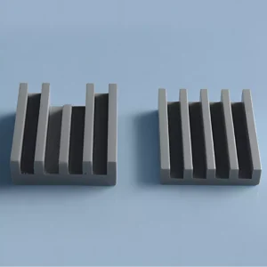
If the SiC wafer requires holes, grooves, slots, steps, flats or special edge cuts, these features should be reviewed before production. Silicon carbide is a hard ceramic material, so feature size, wall distance, edge clearance and machining sequence can affect feasibility and breakage risk.
A drawing is strongly recommended for custom features. When no final drawing is available, customers can provide the intended function, assembly position and key dimensions so ADCERAX can support an initial technical review.
6. Use Proper Packaging for Shipment
SiC wafers should be packed with surface separation, cushioning layers and reinforced outer protection. For polished or precision-ground parts, individual separation and edge protection can be arranged according to wafer size, quantity and shipping route.
Packaging should be selected based on the wafer’s diameter, thickness, surface finish and fragility. Carton packing may be suitable for small and lightweight parts, while wooden case protection can be considered for larger, heavier or more fragile shipments.
7. Confirm Special Requirements Before Quotation
For semiconductor-related equipment use, please provide the drawing, surface requirement, cleanliness requirement, inspection criteria and working environment during RFQ review. ADCERAX will confirm whether the requested specification is suitable before quotation.
If the project requires semiconductor-grade crystal quality, epi-ready surface condition, resistivity control, defect density data or wafer-contact process compatibility, these requirements should be clearly stated in advance for technical confirmation.
How to Specify a Silicon Carbide Wafer for RFQ
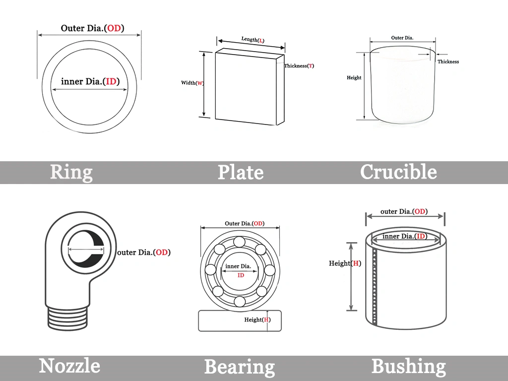
To help ADCERAX provide a practical quotation, please include the following information when sending an RFQ: required diameter, thickness, quantity, surface finish, tolerance, edge condition, drawing file, working temperature, contact media and whether the wafer will be used as a structural ceramic part, thermal component, test substrate or semiconductor-related process item.
If the wafer requires electrical type, crystal orientation, resistivity, defect density, epi-ready surface or wafer-level inspection data, please list these requirements clearly. These items require additional technical confirmation before quotation.