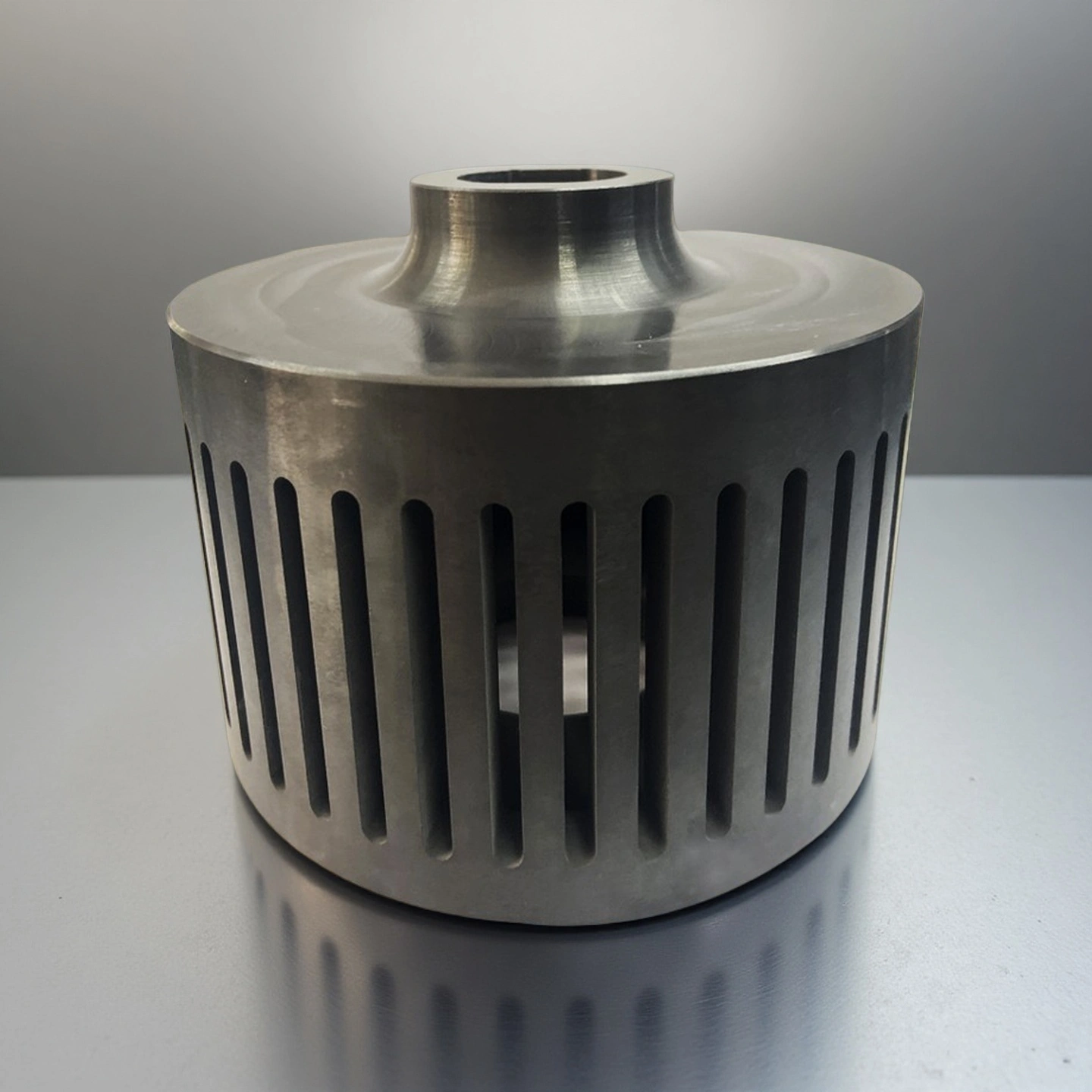
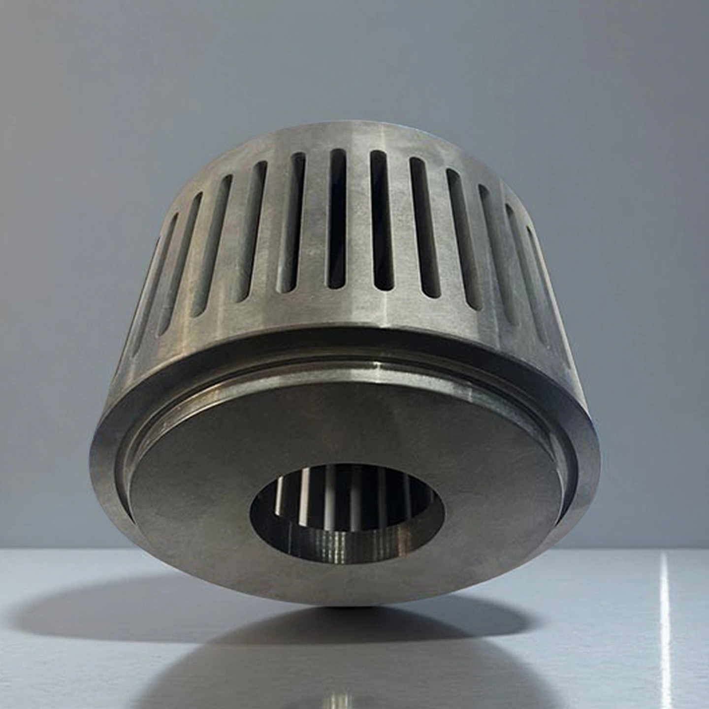
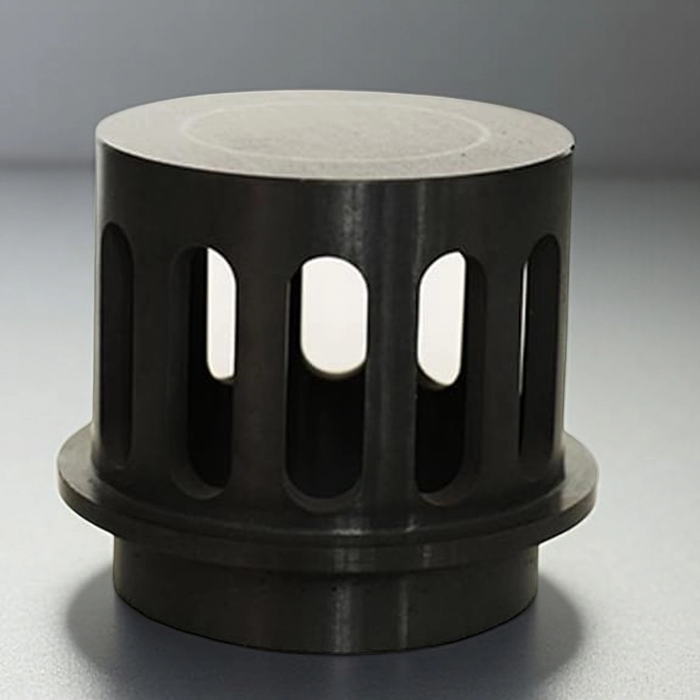
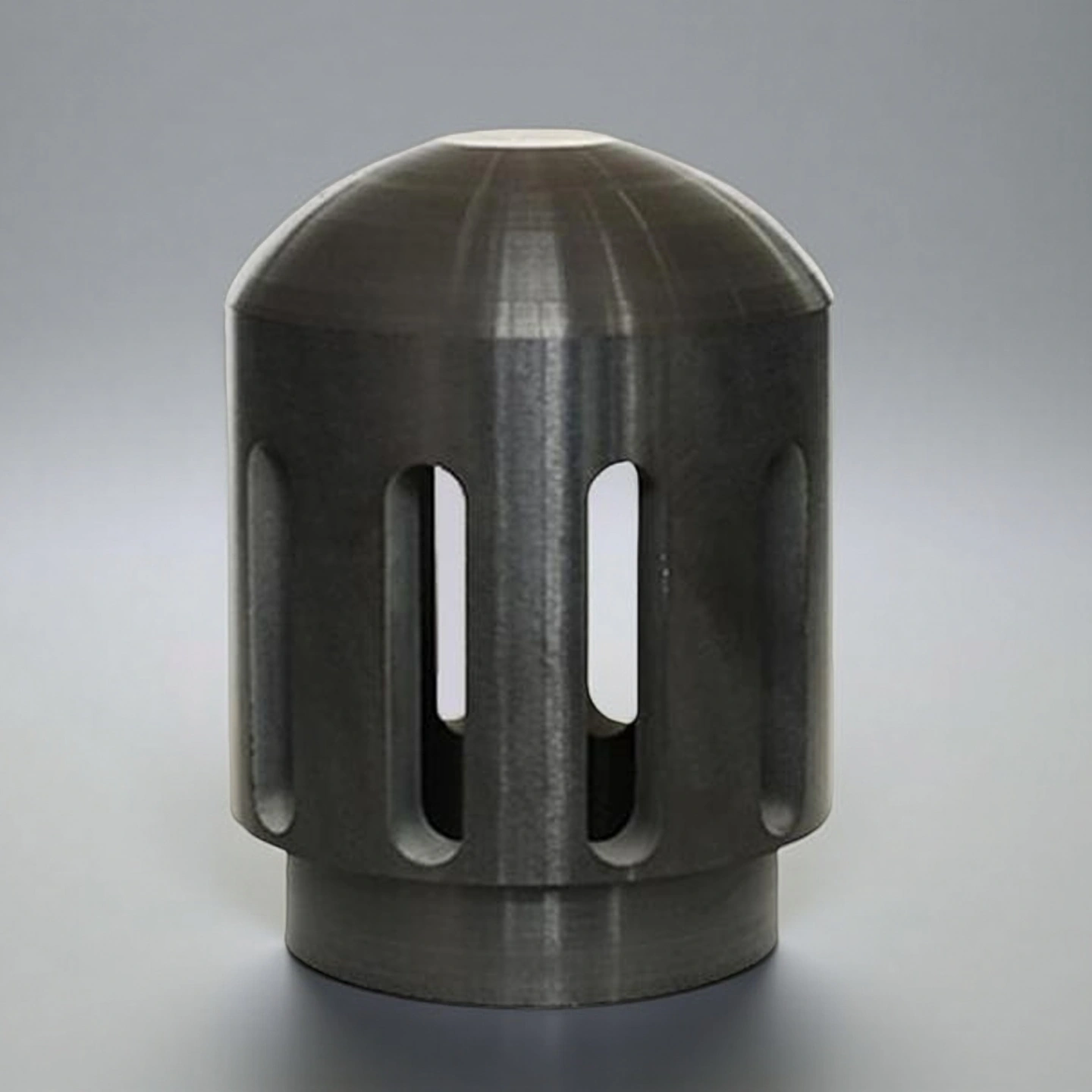
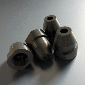
Silicon Nitride Ceramic Grading Wheel for Air Classifiers
The silicon nitride ceramic grading wheel is a Si3N4 classifier rotor for air classifiers and jet mills, available in diameters from about 150 mm up to 600 mm with custom bores and blade geometries to match your air classifier design and target cut size.
A silicon nitride ceramic grading wheel, also called a Si3N4 ceramic classifier wheel or classifying wheel, is a rotating ceramic rotor used inside air classifiers, jet mills and ACM mills to separate fine powder fractions by particle size.
Compared with metal classifier wheels, silicon nitride offers high hardness, low density, good wear resistance and reduced metallic contamination. This makes it suitable for battery materials, advanced ceramic powders, electronic ceramic powders and selected metal powder classification processes where particle size control and material cleanliness are important.
Why Use Si3N4 for Ceramic Classifier Wheels?
Classification Process Requirement
Why Si₃N₄ Helps
Metallic contamination
The ceramic flow-contact surface helps reduce direct metal contact with sensitive powders.
Rotor wear
Silicon nitride offers high hardness and wear resistance for abrasive powder classification.
High-speed operation
Its lower density compared with many metals helps reduce rotor inertia.
Dimensional stability
Properly machined Si₃N₄ supports stable blade geometry during repeated operation.
Custom installation
Bore, hub, blade, keyway and mounting interfaces can be designed according to the classifier structure.
Silicon Nitride Ceramic Grading Wheel Benefits
High wear resistance: Extends service life in abrasive powder environments.
Non-metallic: Prevents contamination in high-purity powder processing.
Thermal shock resistance: Suitable for rapid temperature changes in jet milling.
Corrosion resistance: Withstands chemical exposure in fine powder systems.
Si3N4 Ceramic Grading Wheel Properties
The values below are typical reference data for material and preliminary selection. Final specifications, tolerance and balance requirements should be confirmed according to the drawing, rotor size, classifier model and operating speed.
Si3N4 Type
Gas pressure sintering Si3N4
Hot pressing sintering Si3N4
High thermal conductivity Si3N4
Density (g/cm3)
3.2
3.3
3.25
Flexural Strength (MPa)
700
900
600~800
Young Modulus (GPa)
300
300
300~320
Poisson's ratio
0.25
0.28
0.25
Compressive strength (MPa)
2500
3000
2500
Hardness (GPa)
15
16
15
Fracture toughness (MPa*m1/2)
5~7
6~8
6~7
Maximum working temperature (℃)
1100
1300
1100
Thermal conductivity (W/m*K)
20
25
80~100
Thermal expansion coefficient (/℃)
3*10-6
3.1*10-6
3*10-6
Thermal shock resistance (ΔT ℃)
550
800
/
Si3N4 Ceramic Grading Wheel Specifications
Si3N4 Ceramic Grading Wheel
Item No.
Outer Diameter(mm)
Inner Diameter(mm)
Height(mm)
Upper limit of linear speed m/s
AT-SIN-FJ001
100
75
80
70
AT-SIN-FJ002
155
135
95
70
AT-SIN-FJ003
250
220
100
70
AT-SIN-FJ004
260
240
120
70
AT-SIN-FJ005
315
265
120
70
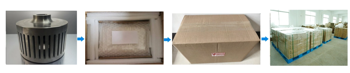
Si3N4 Classifier Wheel Packaging
Each silicon nitride ceramic grading wheel is wrapped with foam or soft cushioning material to protect blades and edges.
Applications of Silicon Nitride Ceramic Grading Wheels
Lithium Battery Cathode and Anode Materials
Key Process Requirements
1. Battery powder classification requires stable particle size control within the target D50 and D97 range.
2. Cathode and anode powders need low metallic contamination during repeated air classification.
3. High-speed classifier rotors must maintain blade geometry under continuous powder impact and airflow load.
Engineering Value
Battery material production lines often require consistent powder cut size to support electrode density, coating uniformity and downstream process stability. If a metal rotor or low-grade ceramic rotor wears unevenly, the particle size distribution may shift and increase the risk of reprocessing or off-spec batches. A silicon nitride ceramic grading wheel helps reduce metal contact, maintain rotor profile and support stable classification in high-value cathode and anode powder processing.
Advanced Ceramic and Electronic Ceramic Powders
Key Process Requirements
1. Ceramic powder classification requires clean material contact for alumina, Si3N4, AlN and electronic ceramic powders.
2. The grading wheel should resist abrasive powder flow while maintaining accurate cut size.
3. Stable classification supports predictable pressing, sintering shrinkage and final ceramic performance.
Engineering Value
Advanced ceramic and electronic ceramic powders must be classified with controlled particle size distribution before spray drying, pressing or sintering. When the classifier wheel wears, deforms or loses blade accuracy, the powder PSD can widen and affect batch consistency. A Si3N4 ceramic grading wheel provides wear resistance, dimensional stability and reduced metallic contamination risk, making it suitable for fine ceramic powder and electronic material processing lines.
Metal Powder for Additive Manufacturing and Powder Metallurgy
Key Process Requirements
1. Metal powder classification requires stable separation of usable and oversized powder fractions.
2. The rotor material should reduce unnecessary contamination in high-value metal powder streams.
3. Consistent rotor geometry helps maintain powder flowability, packing behavior and repeatable classification results.
Engineering Value
Additive manufacturing and powder metallurgy powders depend on controlled particle size distribution and stable flow properties. If classification becomes unstable, too much powder may fall outside the usable size range and require reprocessing or disposal. A silicon nitride ceramic grading wheel can be customized for the target cut size, powder type and classifier structure, helping producers maintain more usable powder within the required PSD window and reduce rotor-related process variation.
Installation and Handling Guidelines for Si3N4 Ceramic Classifier Wheels
Because a silicon nitride ceramic grading wheel is a precision rotating ceramic component, installation and operation should follow both the rotor drawing and the air classifier manufacturer’s safety limits. Proper alignment, controlled fitting, clean contact surfaces and speed verification help reduce stress concentration and vibration risk during operation.
Installation
1. Inspect the silicon nitride ceramic grading wheel for visible chips or cracks before installing.
2. Clean the classifier shaft and bore surfaces to remove dust, oil, and burrs.
3. Align the bore and shaft keys carefully to avoid point loading on the ceramic bore.
4. Use controlled fitting methods (such as gentle heating of the hub or precise pressing) to avoid impact.
5. After installation, check axial run-out and balance according to your classifier manufacturer’s limits.
Operation
1. Start the classifier at low speed to confirm vibration levels and noise are within normal operating ranges.
2. Increase rotor speed gradually to the target set-point while monitoring current, vibration, and throughput.
3. Operate within the recommended maximum rotational speed or peripheral velocity defined for the rotor design.
4. Avoid running with strong unbalanced powder loads for extended periods, as this increases bending stress in the rotor.
Storage
1. Store spare Si3N4 ceramic grading wheels in dry, clean areas away from impact and vibration sources.
2. Keep rotors upright or in dedicated cradles so blades and outer edges are not loaded or pressed against hard surfaces.
3. Avoid stacking heavy objects on top of the packed rotor boxes.
Cleaning and inspection
1. Use soft brushes or compressed clean air to remove dust from the blades and hub.
2. Do not use steel tools or aggressive mechanical scraping directly on ceramic surfaces.
3. Inspect rotor blades for local chipping, cracks, or severe erosion during planned shutdowns.
4. Replace the rotor if any critical cracks are observed or if the blade profile is significantly reduced.
Common misuse points and how to avoid them
1. Over-speeding the rotor
Risk: Exceeding design speed raises stress and may initiate cracks.
Action: Always confirm the rated maximum speed for your silicon nitride ceramic grading wheel and set safety limits in your control system.
2. Impact during installation
Risk: Hammer blows on the hub or shaft can create micro-cracks that grow during operation.
Action: Use controlled fitting tools and follow a step-by-step installation procedure without direct impact.
3. Running with severe imbalance
Risk: Accumulated coarse powder on one side of the rotor can create high bending loads.
Action: Keep the system clean, check balance indicators, and schedule cleaning if vibration trends increase over time.
Silicon Nitride Ceramic Grading Wheel FAQ
Q: What is a silicon nitride ceramic grading wheel used for? A: A silicon nitride ceramic grading wheel is a Si3N4 classifier rotor used in air classifiers, jet mills and ACM mills to separate fine powder fractions and control particle size distribution in high-value powder processing lines.
Q: Why choose Si3N4 instead of a metal classifier wheel? A: Si3N4 helps reduce direct metallic contamination, offers high wear resistance and provides lower density than many metallic rotor designs. This makes it suitable for battery powders, ceramic powders and other materials where cleanliness and stable classification are important.
Q: Can ADCERAX customize the blade geometry of a ceramic grading wheel? A: Yes. ADCERAX can customize blade number, blade thickness, blade angle, curvature, bore size, hub design and mounting interface according to drawings, existing rotor samples or classifier requirements.
Q: What information is needed for a custom Si3N4 classifier wheel quotation? A: Useful information includes outer diameter, bore size, rotor height, blade geometry, classifier model, powder type, target D50 or D97, operating speed, mounting method and quantity. Drawings or photos of the existing rotor help speed up the engineering review.
Q: Is a silicon nitride grading wheel suitable for battery powder classification? A: It can be suitable when the process requires low metallic contamination, wear resistance and stable classification of cathode or anode powders. Final material selection should be confirmed according to powder abrasiveness, target particle size and equipment speed.
Q: How should a Si3N4 ceramic grading wheel be installed and handled? A: The rotor should be inspected for chips or cracks before installation, aligned carefully with the shaft or hub, fitted without hammer impact and operated within the equipment’s rated speed and balance limits.
RFQ Checklist for a Custom Silicon Nitride Classifier Wheel
To quote a custom Si3N4 ceramic grading wheel accurately, please provide as much application information as possible. Drawings, photos and existing rotor dimensions are especially useful for confirming manufacturability and installation fit.
RFQ Information
Why It Matters
Drawing or sample photos
Confirms overall rotor structure and mounting interface.
Classifier or jet mill model
Helps review chamber space, speed and installation method.
Outer diameter, bore and height
Defines the basic machining and forming requirements.
Blade number and blade geometry
Affects airflow, cut size and classification stability.
Powder material
Determines wear, contamination and cleaning requirements.
Target D50 / D97
Helps match the grading wheel to process goals.
Operating speed
Needed for mechanical safety review and balance discussion.
Quantity and replacement cycle
Helps confirm production method and cost structure.
Custom Design Parameters for Si3N4 Ceramic Grading Wheels
ADCERAX supplies silicon nitride ceramic grading wheels according to customer drawings, existing rotor samples or equipment requirements. Before production, our team reviews the classifier model, powder type, target particle size distribution, rotor speed, mounting interface and balance requirements to confirm whether Si3N4 is suitable for the application.
1. Overall geometry
Outer diameter range, for example 150–600 mm (larger or smaller sizes on request)
Inner bore diameter, keyway, or spline profile to match your classifier shaft
Total rotor height, hub thickness, and flange width
2. Blade design
Number of blades and their spacing around the grading wheel
Blade thickness, chord length, and tip width influence cut sharpness
Blade angle and curvature relative to the gas flow and powder trajectory
3. Mechanical and speed limits
Maximum design rotational speed or peripheral velocity for the rotor
Safety factor for continuous operation at your typical classifier speed
4. Dimensional accuracy
Tolerances for OD, bore, hub faces, and key working surfaces
Critical fits are achievable in the range of approximately ±0.03–0.05 mm, depending on size
5. Mounting interface
Fixing method options such as shrink fit, keyed fit, clamping hub, or bolted flange
Location and size of bolt holes or dowel holes when required
6. Balance and running quality
Target balance quality grade for dynamic balancing according to your machine limits
Provision for balance correction planes if your classifier requires very low vibration
7. Surface condition
Surface finish of hub faces, bore, and reference shoulders (ground, fine machined, or as-sintered where acceptable)
Optional edge chamfers or radii on blades and hubs to reduce stress concentrations