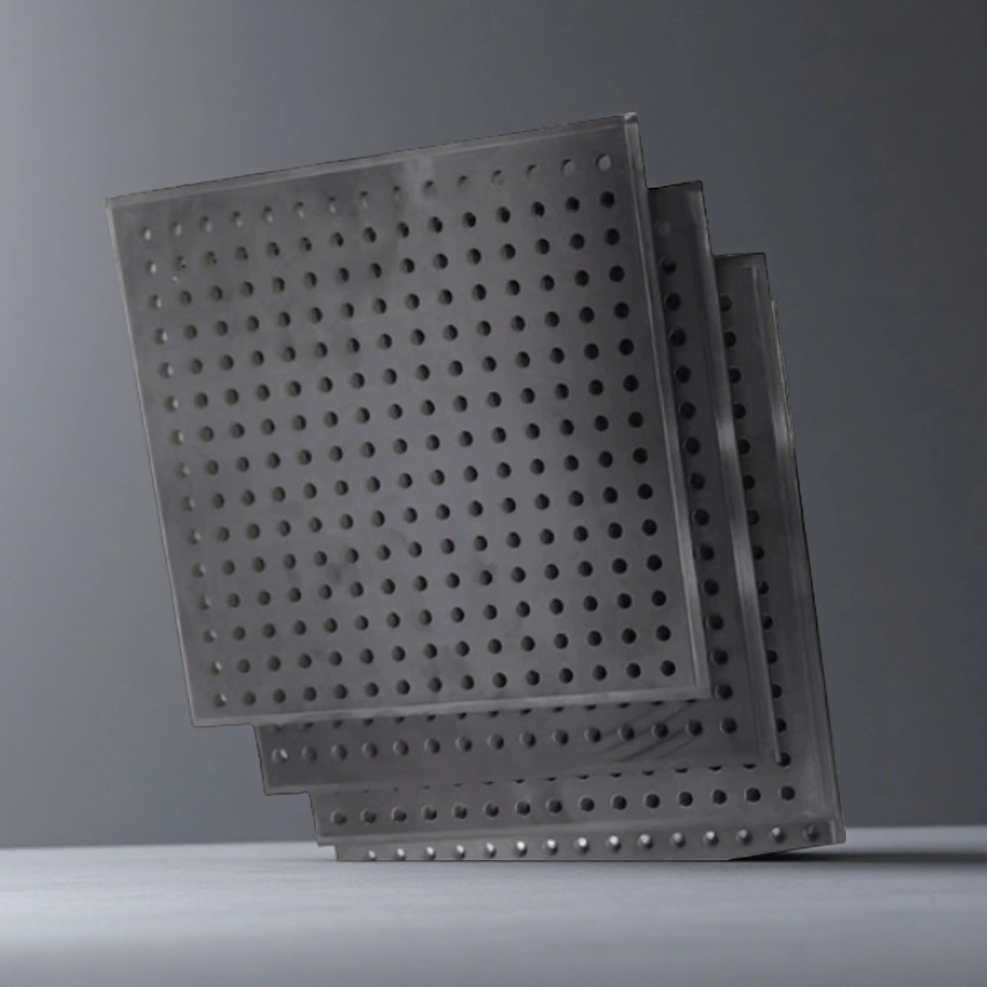
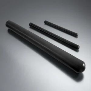
ADCERAX supplies custom silicon nitride gas baffles for aluminum melting, holding, recycling and rotary degassing furnace systems. These Si₃N₄ ceramic plates and discs are used to guide hot gas flow, reduce direct flame disturbance, stabilize furnace atmosphere movement and protect high-wear flue or rotor-side areas.
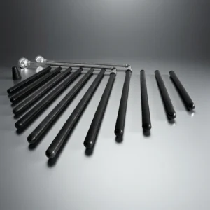
Solid, perforated and segmented designs are available according to furnace drawings, burner position, flue layout, rotor clearance, open-area requirements and existing mounting hardware.
A silicon nitride gas baffle is a high-temperature Si₃N₄ ceramic plate, disc or segmented flow-control component used inside aluminum melting furnaces, holding furnaces, recycling furnaces and rotary degassing systems. It helps redirect hot gas, stabilize melt-side flow conditions, reduce localized wear near flues or rotors, and provide a more durable alternative to cast refractory baffles in selected aluminum furnace applications.
Silicon Nitride Gas Baffle Benefits
Stable Geometry in Furnace Cycling Silicon nitride helps the baffle keep a more stable shape than many cast refractory plates during repeated heating and cooling, reducing the risk of flow-path drift caused by warping or edge damage.
Low Aluminum Wetting Behavior Si₃N₄ shows low wetting tendency against molten aluminum, helping reduce metal build-up around holes, edges and gas passages when the baffle is used near the melt or rotor zone.
Custom Flow-Control Geometry Hole pattern, open area, central cut-out, slot shape and segmentation can be designed around the actual burner, flue, rotor and furnace roof layout instead of using a generic refractory plate.
Better Fit for Maintenance Planning Drawing-based ceramic baffles help maintenance teams standardize replacement parts, define inspection points and reduce emergency modification during scheduled furnace shutdowns.
Si₃N₄ Material Grade Options for Gas Baffle Design
The values above are reference material data. Final gas baffle design should be reviewed according to furnace atmosphere, support method, thermal cycling, gas-flow exposure and contact risk with molten aluminum.
Si3N4 Type
Gas pressure sintering Si3N4
Hot pressing sintering Si3N4
High thermal conductivity Si3N4
Density (g/cm3)
3.2
3.3
3.25
Flexural Strength (MPa)
700
900
600~800
Young Modulus (GPa)
300
300
300~320
Poisson's ratio
0.25
0.28
0.25
Compressive strength (MPa)
2500
3000
2500
Hardness (GPa)
15
16
15
Fracture toughness (MPa*m1/2)
5~7
6~8
6~7
Maximum working temperature (℃)
1100
1300
1100
Thermal conductivity (W/m*K)
20
25
80~100
Thermal expansion coefficient (/℃)
3*10-6
3.1*10-6
3*10-6
Thermal shock resistance (ΔT ℃)
550
800
/
Si3N4 Gas Baffle Specifications
Silicon Nitride Gas Baffle
Item No.
Diameter (mm)
Thickness (mm)
AT-SN-BS001
Customize
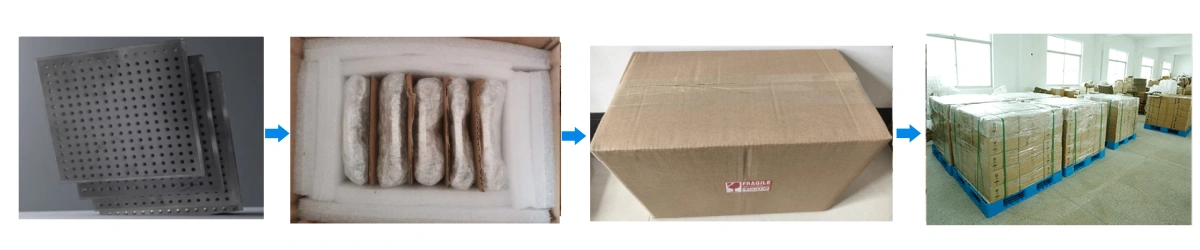
Silicon Nitride Gas Baffle Plate Packaging
Silicon nitride gas baffles are wrapped in soft protective layers and packed in reinforced wooden or heavy-duty cartons to prevent edge chipping.
Silicon Nitride Gas Baffle Applications
Aluminum Melting and Holding Furnaces
In melting and holding furnaces, a silicon nitride gas baffle can be placed near the roof, flue or hot-gas path to guide combustion gas movement and reduce direct disturbance over the molten bath. This is useful when the existing refractory baffle suffers from cracking, edge wear, aluminum build-up or unstable gas flow near the flue opening.
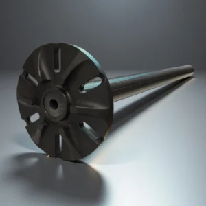
Rotary Degassing Units
In rotary degassing systems, a disc-type Si₃N₄ baffle can be designed around the rotor shaft to help distribute inert gas bubbles and stabilize melt movement around the treatment zone. The design should be reviewed together with rotor diameter, immersion depth, shaft clearance and bath geometry.
Aluminum Recycling Furnaces
Recycling furnaces often process variable scrap loads, so the hot-gas path may become unstable from charge to charge. A custom silicon nitride baffle can help redirect local gas flow and protect high-wear areas near the roof, outlet or flue region.
Furnace Retrofit and Replacement Projects
For retrofit projects, ADCERAX can review the existing refractory baffle, broken sample, sketch or furnace drawing to evaluate whether a solid, perforated or segmented Si₃N₄ design is more suitable for the available support structure.
Silicon Nitride Gas Baffle Usage Instructions
Proper installation, heating control and handling are important for silicon nitride gas baffles used in aluminum melting, holding, recycling and rotary degassing furnace systems. The following guidance helps reduce installation damage, thermal-stress cracking and unexpected wear during furnace operation.
Pre-Installation Check
Before installation, confirm that the baffle size, hole pattern, open area, mounting position and support-frame geometry match the furnace drawing or approved replacement design. Inspect the ceramic surface, edges, holes and slots for shipping damage before placing the part into the furnace.
Check the support frame carefully. Contact surfaces should be flat, clean and free of slag, weld beads, sharp metal points or loose refractory debris. Uneven seating may create local stress and increase the risk of cracking during thermal cycling.
Installation Guidance
Place the silicon nitride gas baffle gently onto the prepared support area. Do not hammer the ceramic into position or force it against a distorted frame. For segmented baffle panels, keep the designed clearance between sections and confirm that each panel is evenly supported.
For rotary degassing or rotor-side baffle designs, verify shaft clearance, rotor position, immersion depth and the distance between moving parts and the ceramic baffle before operation. The baffle should not contact the rotor, shaft, fixtures or charging tools during furnace use.
Heating and Operation
Use controlled heating and cooling whenever possible. Rapid temperature changes, direct cold-air exposure, emergency water contact or sudden furnace shutdown may create strong thermal gradients across the ceramic body.
During operation, monitor whether gas flow, flame direction, flue draft or melt movement changes after installation. If abnormal vibration, direct flame impingement, unexpected metal contact or severe build-up appears, stop and inspect the baffle during the next safe maintenance window.
Cleaning and Maintenance
Clean the baffle with controlled tools and avoid aggressive impact. Do not strike hole edges, slots, chamfers or unsupported areas with metal tools. For perforated and segmented designs, inspect hole edges, mounting points and support contact areas during planned maintenance.
If cracks, chips, abnormal wear or deformation of the support structure are found, review the furnace layout and current failure mode before ordering a replacement. A modified hole pattern, thicker section, larger edge radius, different segmentation layout or improved support design may be needed.
Typical Misuse Points and Handling
Misuse Point
Risk
Handling Recommendation
Rapid heating or emergency cooling
Large thermal gradients may cause cracking, especially near direct flame, flue openings or uneven hot-gas zones.
Use controlled heating and cooling ramps whenever possible, and avoid sudden exposure to cold air, water or rapid furnace shutdown conditions.
Uneven support or point loading
Local stress may damage ceramic edges, corners or mounting areas, especially on large plates or segmented baffles.
Keep all support surfaces flat, clean and evenly loaded. Avoid warped frames, debris, weld beads or sharp metal contact points.
Mechanical impact from tools or scrap
Chips or cracks may occur during charging, cleaning or maintenance if the ceramic is hit by tools, scrap metal or furnace fixtures.
Treat the baffle as a structural ceramic component. Avoid hammering, prying, dropping or using metal tools directly on the ceramic surface.
Incorrect rotor, burner or flue clearance
Gas flow may not follow the intended path, and the baffle may face unexpected vibration, flame impingement or mechanical contact.
Confirm drawing dimensions before installation, including rotor clearance, flue position, burner direction, open-area layout and support-frame geometry.
Excessive cleaning force
Aggressive scraping or impact cleaning may damage hole edges, slots, chamfers or unsupported sections.
Remove build-up with controlled tools and avoid concentrated force on perforations, thin edges or unsupported areas.
Silicon Nitride Ceramic Gas Baffle FAQ
Q: What information is needed to quote a custom silicon nitride gas baffle? A: ADCERAX usually needs the furnace type, working position, overall size, thickness, hole or slot layout, flue and burner location, mounting method, operating temperature, atmosphere and the failure mode of the existing baffle. Drawings, sketches, photos or broken samples are helpful for engineering review.
Q: Can a silicon nitride gas baffle replace a cast refractory baffle directly? A: It may replace a cast refractory baffle in selected aluminum furnace positions, but the design should not be copied blindly. Ceramic thickness, support contact area, edge clearance, thermal expansion allowance and perforation layout should be reviewed before replacement.
Q: How should the hole pattern or open area be selected? A: Hole pattern and open area should be selected according to the target gas path, flue position, burner direction, rotor clearance and allowable pressure drop. ADCERAX can produce round holes, slots, central openings and segmented layouts based on the customer’s furnace drawing.
Q: What causes a silicon nitride gas baffle to crack during service? A: Common causes include uneven support, point loading, rapid heating or cooling, mechanical impact during charging, aggressive cleaning tools and unexpected contact with scrap or fixtures. Proper seating, controlled thermal cycles and careful handling help reduce cracking risk.
Q: Is silicon nitride suitable for contact with molten aluminum? A: Silicon nitride is widely used in selected molten aluminum handling components because of its low wetting tendency and thermal shock resistance. Final suitability still depends on alloy chemistry, temperature, atmosphere, contact time and mechanical loading.
Q: Can ADCERAX supply segmented gas baffles for large furnace openings? A: Yes. Large baffles can be reviewed as segmented Si₃N₄ panels when one-piece ceramic size, weight or installation risk is too high. Segment layout, joint clearance, support position and installation sequence should be confirmed during design review.
Most silicon nitride gas baffles are not off-the-shelf parts. Furnace geometry, gas direction, burner position, flue opening, rotor clearance and support structure all affect the final design. ADCERAX reviews drawings, sketches, broken samples or existing refractory baffle dimensions before recommending a solid, perforated or segmented Si₃N₄ ceramic design.
1. Overall dimensions
Plate or disc diameter/side length
Thickness range (for mechanical strength and weight)
2. Shape and segmentation
Single-piece plate, disc, or ring
Segmented baffle panels for large roof or flue openings
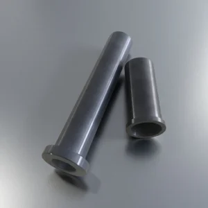
Cut-outs for riser tubes, burners, or inspection openings
3. Perforation and open area
Hole diameters and patterns
Open-area percentage to control gas velocity
Slot or round-hole geometry for specific flow patterns
4. Mounting and support details
Bolt hole pattern
Notches or recesses for support beams
Interfaces with steel frames or refractory hangers
5. Material and surface
Standard dense Si₃N₄ grade for molten aluminum service
Optional surface finish levels on gas-contact or melt-contact sides
Chamfers and rounded edges to reduce stress concentration