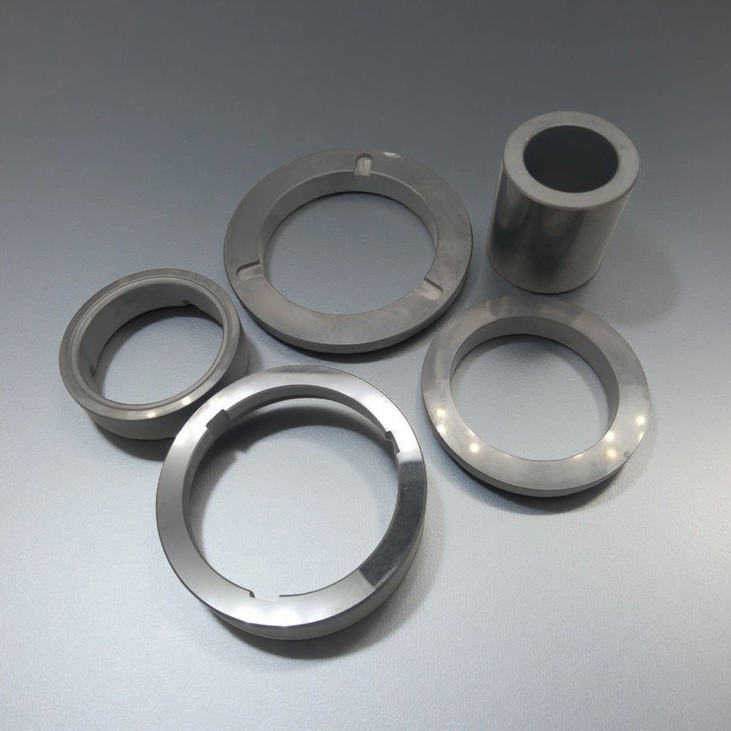
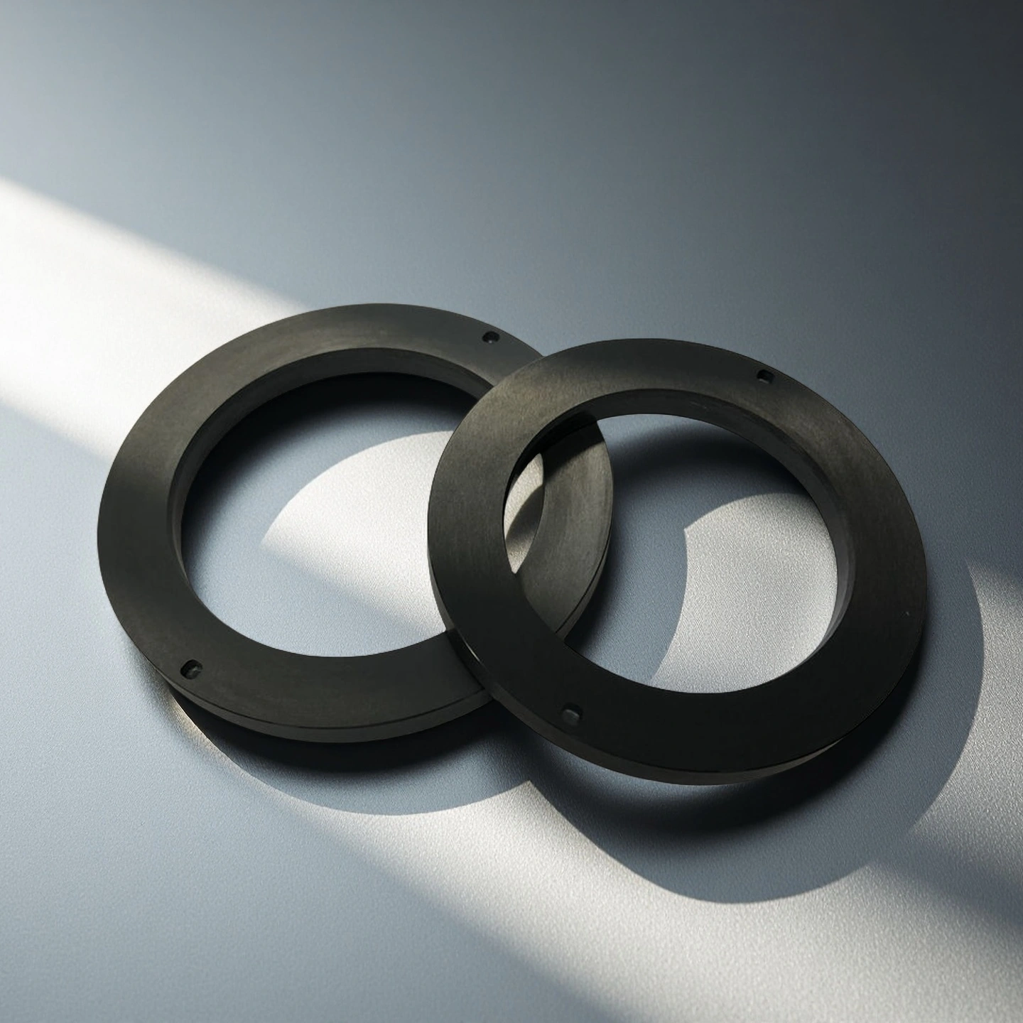
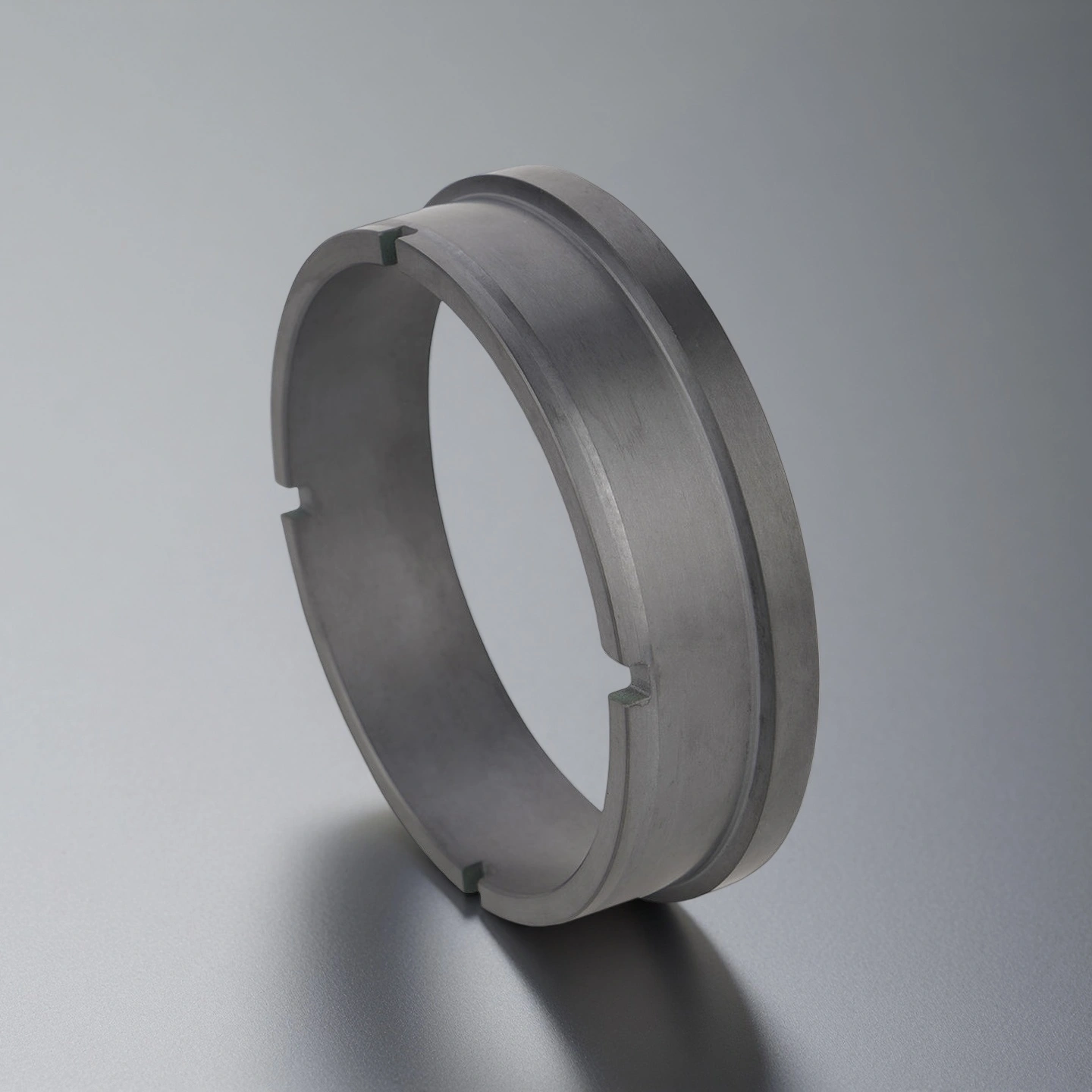
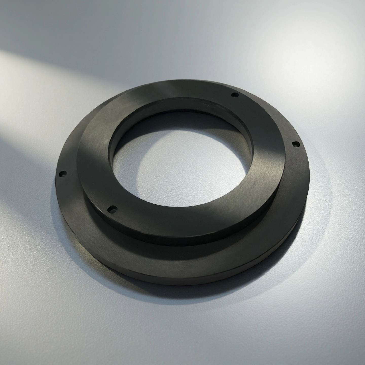
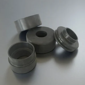
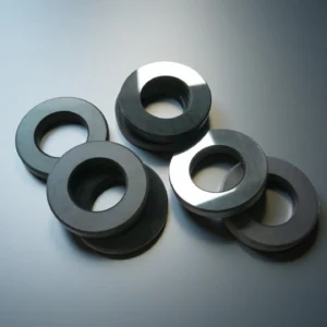
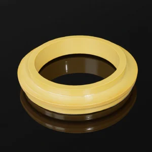
Silicon Nitride Seal Ring is a precision-machined ceramic sealing component made from Si₃N₄ (silicon nitride), designed to serve as a rotating or stationary seal face in mechanical seals, pumps, compressors, and vacuum systems. Its function is to maintain a stable sealing interface under high pressure, temperature variation, and sliding velocity.
Silicon Nitride Seal Ring Benefits
-
Stable Face Geometry
Controlled flatness and parallelism help reduce face gap variation under pressure fluctuation, axial load, and repeated start-stop conditions.
-
Low Rotating Mass
The low-density Si₃N₄ structure helps reduce rotating mass, which can support smoother acceleration and lower load on the sealing assembly.
-
Edge-Chip Mitigation
Controlled chamfer, fillet, and corner radius design helps reduce edge stress during installation, alignment, and thermal cycling.
-
Consistent Lapping Window
Repeatable lapping and surface finish control help support stable initial contact, smoother run-in behavior, and more predictable sealing performance.
-
Pairing Flexibility
Si₃N₄ seal rings can be paired with SiC, tungsten carbide, carbon graphite, or another Si₃N₄ face, depending on media, lubrication, pressure, and speed.
Silicon Nitride Ceramic Seal Ring Properties
|
Si3N4 Type |
Gas pressure sintering Si3N4 |
Hot pressing sintering Si3N4 |
High thermal conductivity Si3N4 |
|
Density (g/cm3) |
3.2 |
3.3 |
3.25 |
|
Flexural Strength (MPa) |
700 |
900 |
600~800 |
|
Young Modulus (GPa) |
300 |
300 |
300~320 |
|
Poisson's ratio |
0.25 |
0.28 |
0.25 |
|
Compressive strength (MPa) |
2500 |
3000 |
2500 |
|
Hardness (GPa) |
15 |
16 |
15 |
|
Fracture toughness (MPa*m1/2) |
5~7 |
6~8 |
6~7 |
|
Maximum working temperature (℃) |
1100 |
1300 |
1100 |
|
Thermal conductivity (W/m*K) |
20 |
25 |
80~100 |
|
Thermal expansion coefficient (/℃) |
3*10-6 |
3.1*10-6 |
3*10-6 |
|
Thermal shock resistance (ΔT ℃) |
550 |
800 |
/ |
Silicon Nitride vs SiC vs Tungsten Carbide Seal Rings
| Material |
Main Advantage |
Limitation |
Suitable Use |
| Silicon Nitride |
Low density, good toughness, and thermal shock resistance. |
Requires careful counterpart selection and face lapping. |
High-speed, intermittent, dry-gas, and vacuum sealing assemblies. |
| Silicon Carbide |
Strong hardness and chemical resistance. |
More brittle under impact or misalignment. |
Abrasive liquids, chemical pumps, and high-wear sealing pairs. |
| Tungsten Carbide |
High hardness and good mechanical strength. |
Higher density and possible corrosion concerns in some media. |
Oil, water, and heavy-duty mechanical seal systems. |
| Carbon Graphite |
Good self-lubricating behavior. |
Lower strength and wear resistance than advanced ceramics. |
Dry gas, vacuum, and low-lubrication counterpart faces. |
Specifications of Si3N4 Seal Ring
Si3N4 Seal Ring Packaging
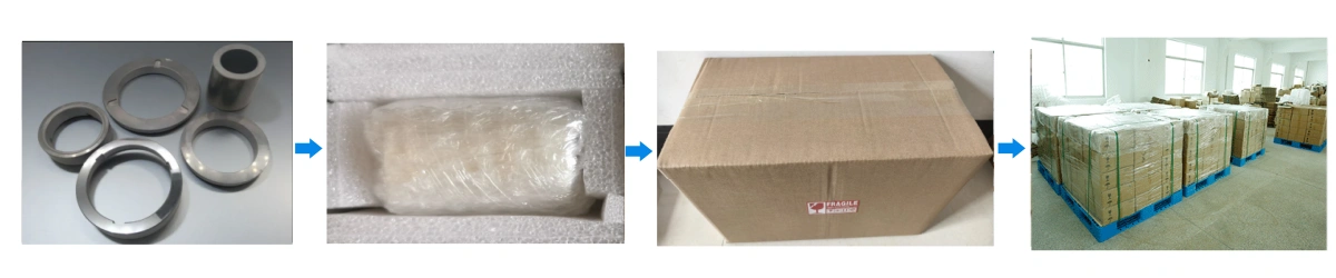
- Clean room-grade pouch → anti-static tray → foam-lined carton. Single-piece separators prevent face rub.
How to Specify a Silicon Nitride Seal Ring
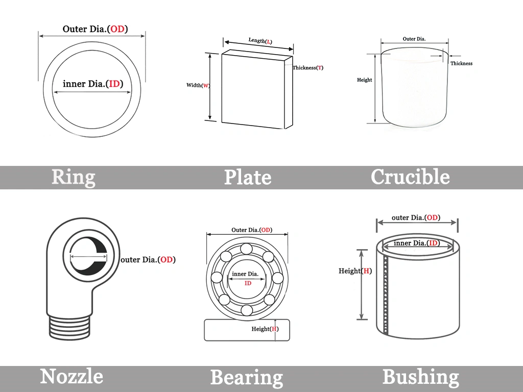
To specify a silicon nitride seal ring, engineers should confirm the ring geometry, mating material, sealing media, operating temperature, pressure-velocity condition, lubrication state, and required face finish. ADCERAX reviews drawings, samples, and application conditions before quotation to help match the Si₃N₄ ring design with the actual sealing environment.
| Specification Item |
What to Confirm |
Why It Matters |
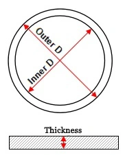
| ID / OD / Thickness |
Drawing dimensions, tolerance range, and assembly clearance. |
Ensures the ring fits the seal housing and shaft design. |
| Face Width |
Contact track width and counterpart face size. |
Affects sealing film stability and friction behavior. |
| Flatness / Parallelism |
Required inspection band based on seal duty. |
Helps control leakage risk and uneven face loading. |
| Surface Finish |
Ra / Rz range and lapping direction. |
Influences run-in, fluid film formation, and friction. |
| Counterpart Material |
SiC, carbon graphite, tungsten carbide, or Si₃N₄. |
Determines wear pairing and thermal compatibility. |
| Media Condition |
Liquid, gas, slurry, solvent, or vacuum environment. |
Helps judge corrosion, particle, and lubrication risks. |
| Edge Design |
Chamfer, radius, groove, or notch requirements. |
Reduces chipping during installation and operation. |
Silicon Nitride Seal Ring Usage Instructions
The values below are typical handling and design reference points. Final operating limits should be confirmed according to seal design, mating material, media, pressure, speed, and customer test conditions.
-
Installation
1. Inspect seat bore and shaft run-out: Verify Total Indicator Reading (TIR ≤ 0.02 mm) for shafts ≤50 mm diameter. Exceeding tolerance may cause uneven contact, increasing face load and thermal distortion.
2. Handle with face protectors at all times: Avoid direct metal-to-face or face-to-face contact. Use PTFE gloves to prevent micro-scratch and oil contamination.
3. Use alignment sleeves and jigs: Ensure axial preload and spring compression fall within design range; misalignment can generate edge loading and premature leakage.
4. Confirm pairing material and flatness band: Match to SiC, TC, carbon, or Si₃N₄ counterparts. Verify both surfaces conform to required Ra band (≤0.02–0.05 μm) for consistent film formation.
5. Tightening sequence: Secure bolts diagonally and progressively to maintain concentricity. Torque deviation should not exceed ±5% between bolts on the same flange.
-
Operation
1. Stay within PV limits: Do not exceed the specified pressure-velocity product (≤ 2.5 MPa·m/s). Maintain proper flush pressure and flow to prevent dry-run and vapor locking.
2. Monitor operational parameters: Track start-stop cycles, shaft vibration amplitude, and temperature gradient (ΔT) across the seal. Keep axial run-out below 0.05 mm at full speed.
3. Predictive maintenance: Record leakage rate trends during commissioning and steady operation. A >20% increase from baseline may indicate wear or face distortion.
4. Coolant and barrier plan: For dual seals, maintain barrier fluid pressure 1.5 bar above process side to prevent reverse leakage and heat buildup.
-
Storage
1. Store rings in a dry, dust-free, temperature-stable environment (15–25 °C; RH < 60%).
2. Keep face protectors on during all handling and transport stages.
3. Avoid stacking rings face-to-face; use foam spacers or vacuum-sealed pouches to prevent contact micro-chipping.
4. For long-term storage (>6 months), recheck flatness and Ra prior to assembly.
-
Cleaning
1. Rinse components with filtered solvent or deionized (DI) water depending on process compatibility.
2. Use lint-free microfiber wipes; do not use abrasive cloths, wire brushes, or ultrasonic cleaning without fixturing.
3. Air-dry with oil-free compressed air (<0.1 μm filter); never bake above 120 °C to prevent micro-stress in the polished layer.
4. Avoid acid/base cleaning agents that may etch the silicon nitride surface.
-
Common Misuse & Corrective Actions
1. Chipped edge after assembly
→ Introduce a larger chamfer radius (0.3–0.5 mm); use protective sleeves during installation; check that shaft lead-in radius ≥ 1 mm.
2. Early leakage during commissioning
→ Verify flatness mismatch ≤ 2 μm and preload distribution; increase flush rate or reduce barrier pressure differential; inspect for trapped air pocket at startup.
3. Thermal discolouration or burn marks
→ Indicates dry running or inadequate lubrication film. Reassess PV load, ensure flush flow rate, and re-lap faces to correct micro-distortion. Replace O-rings if hardened by heat.