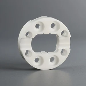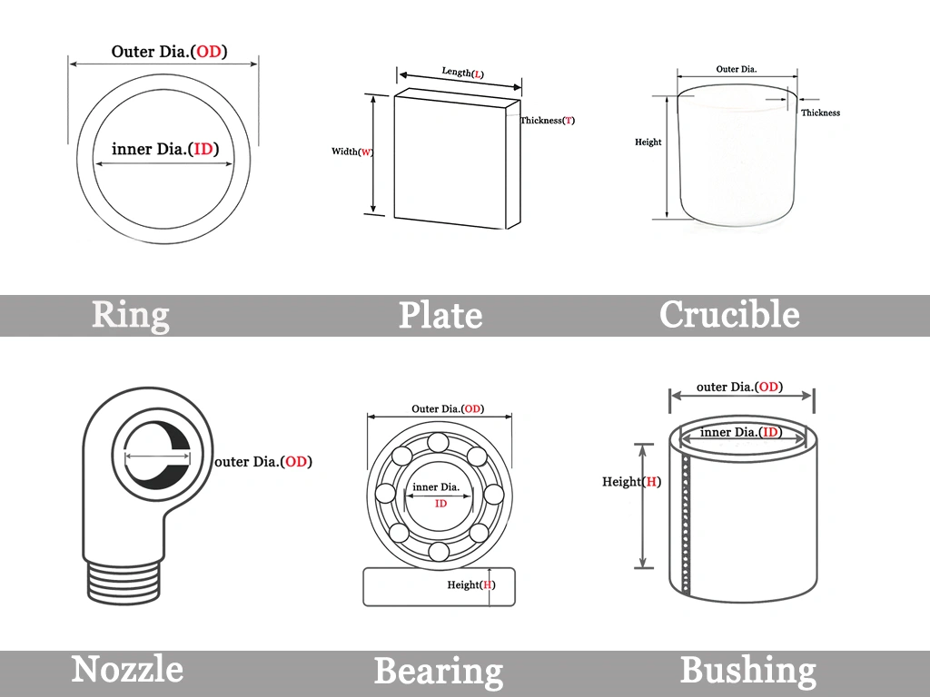
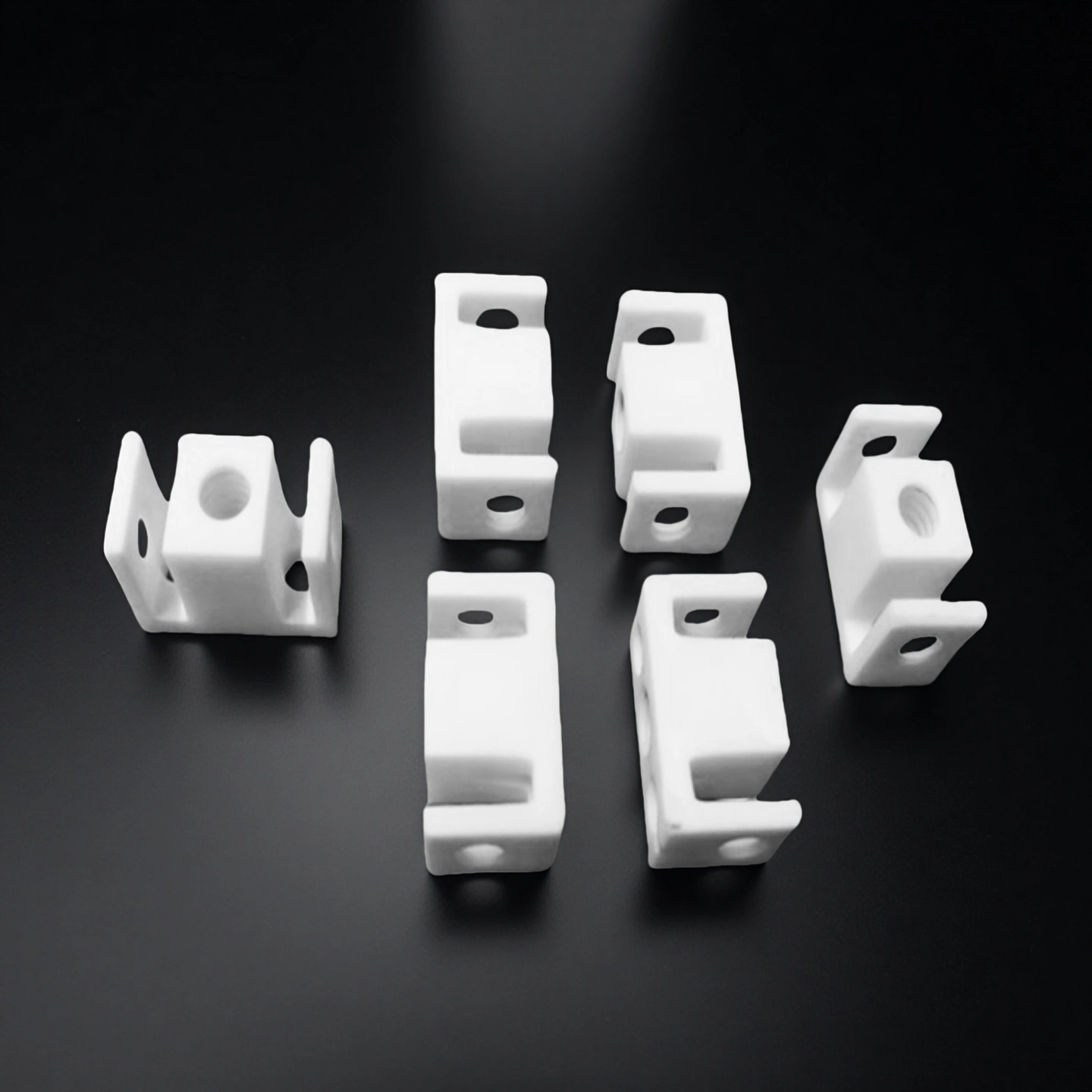
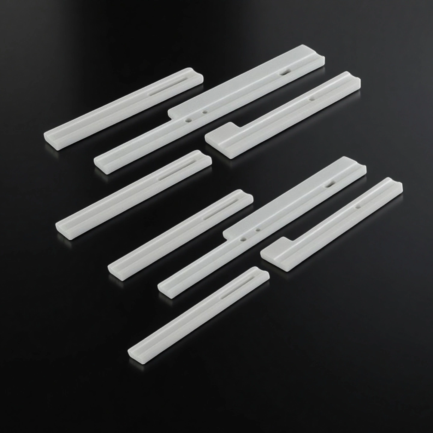

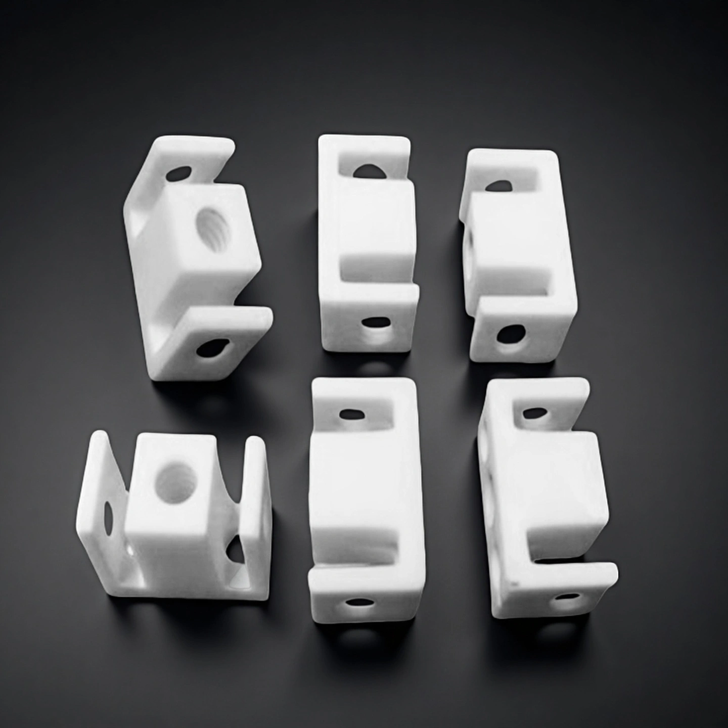
A zirconia ceramic positioning fixture is a drawing-defined locating part — a plate, block, stop or shaped seat — that holds a workpiece at the datum your process calls for while a support face carries the clamping load.
Specifications of Zirconia Positioning Fixture
| Zirconia Positioning Fixture | ||
| Item no. | Length(mm) | Width(mm) |
| AT-YHG-ZJ2001 | Customize | |
Download the Product Catalogue
3Y Zirconia Positioning Fixture for Material Selection
| AD-ZRO-3Y material reference | Value | Selection use/condition |
|---|---|---|
| Vickers hardness | 12.5 GPa | Hard-contact material comparison; test conditions agreed for the order |
| Flexural strength | 800–1000 MPa at 20 °C | Bending-resistance comparison; specimen, surface and loading method apply |
| Fracture toughness, KIC | 7.2–9 MPa·m¹ᐟ² at 20 °C | Crack-resistance comparison; test method applies |
These values describe the material grade. The order specifies the ceramic part dimensions and finish; the workpiece, base and clamping setup establish positioning acceptance.
How to Define a Zirconia Ceramic Positioning Fixture
Most fixture projects start from a drawing, a sketch or an old part. Work through these four choices and the quotation can be built on the geometry you actually need.
1. Choose the locating role
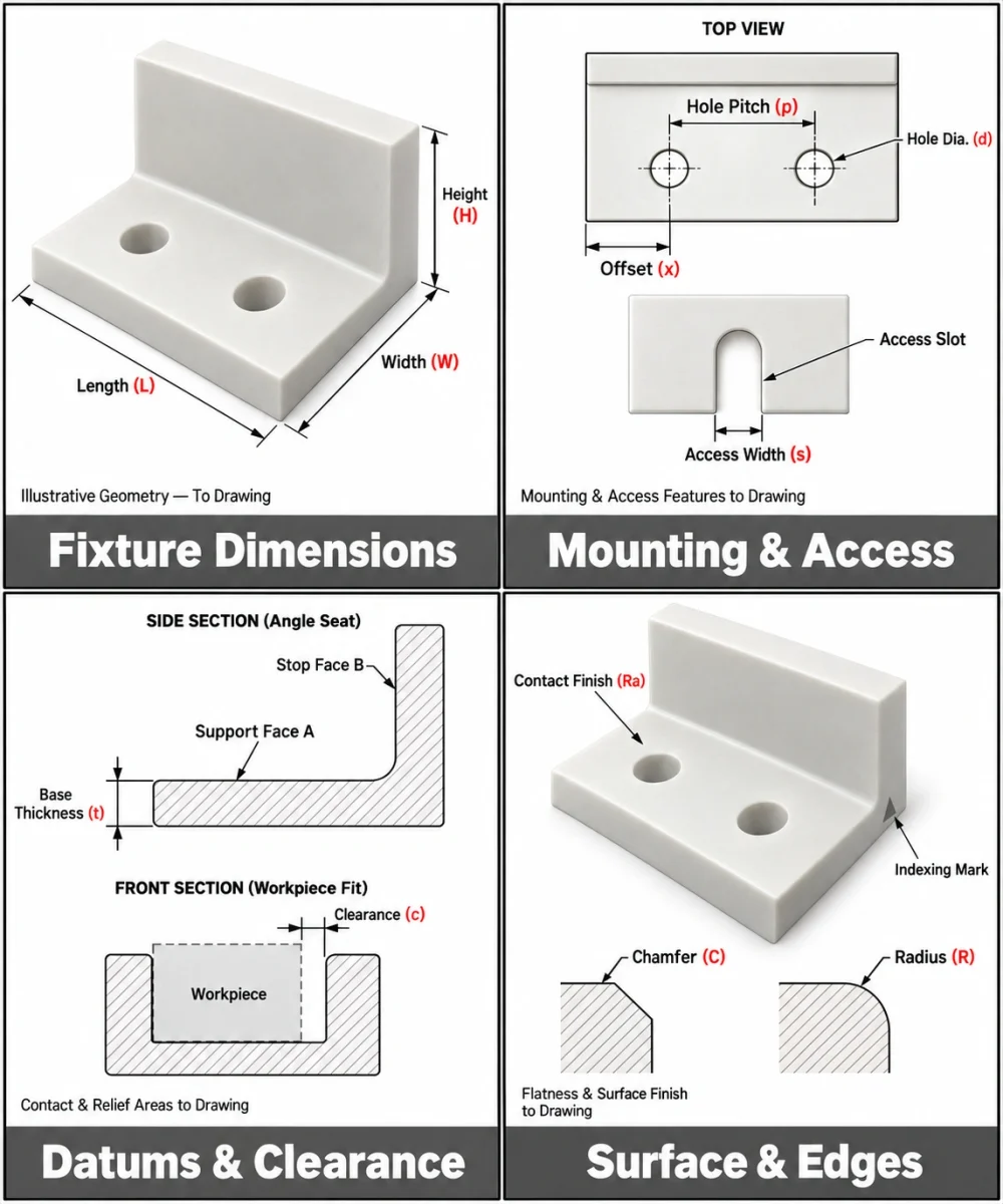
Decide whether the ceramic part locates, guides, supports, clamps, limits travel or checks a feature, and mark which face is the primary datum.
What to define: workpiece datum A/B/C, contact points, restrained degrees of freedom and the inspection reference.
2. Choose the contact geometry
Flat locating faces, stops, grooves, slots and shaped seats each meet a different workpiece profile. Define the contact area, edges and any face that must stay clear of the workpiece.
What to define: contact profile, width and length, corner radii, edge condition and working clearance.
3. Choose the mounting interface
The ceramic part connects to a metal base through holes, seats, inserts or adhesive joints. The fit, hole pattern and fastening method set how the part sits in the tolerance chain.
What to define: base material, hole pattern, fit style, insert or adhesive type and torque limits.
4. Choose the functional surface and edges
Flatness, surface finish and edge condition are specified only where they affect the locating result. State the surface finish on functional faces and the edge treatment on contact rims.
What to define: flatness and surface finish on contact faces, edge chamfers and areas excluded from contact.
Common Failure Modes and How to Avoid Them
- Edge Chipping: Specify chamfers or radii, use padded trays and non-metallic tools, and inspect edges regularly.
- Cracking from Concentrated Loads: Spread loads across defined support areas. Control fits and clamping force to avoid point loading and excessive interference.
- Over-Constraint and Datum Drift: Define the required locating contacts and clearance faces. Verify workpiece position on the first assembled fixture.
- Loose Mounting Interfaces: Specify fasteners, inserts or adhesive joints. Recheck the assembly at agreed intervals to detect movement.
- Contact Wear and Position Drift: Monitor datum-face wear and positioning changes. Set clear rework or replacement limits.
- Thermal and Moisture Effects: Validate fit across operating temperatures. For 3Y zirconia exposed to hot water or steam, assess hydrothermal aging before use.
What to provide: Load direction, clamping method, operating temperature, process media and acceptance criteria for critical contacts.
Packaging of Zirconia Positioning Fixture
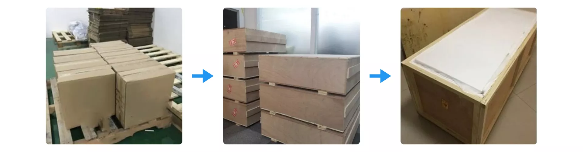
Zirconia Positioning Fixture is securely packed using multilayer protective materials to prevent vibration, shock, or contamination during transit. Each unit is first boxed, then encased in reinforced plywood crates with foam lining for enhanced impact resistance. This packaging system ensures safe delivery for global industrial applications.