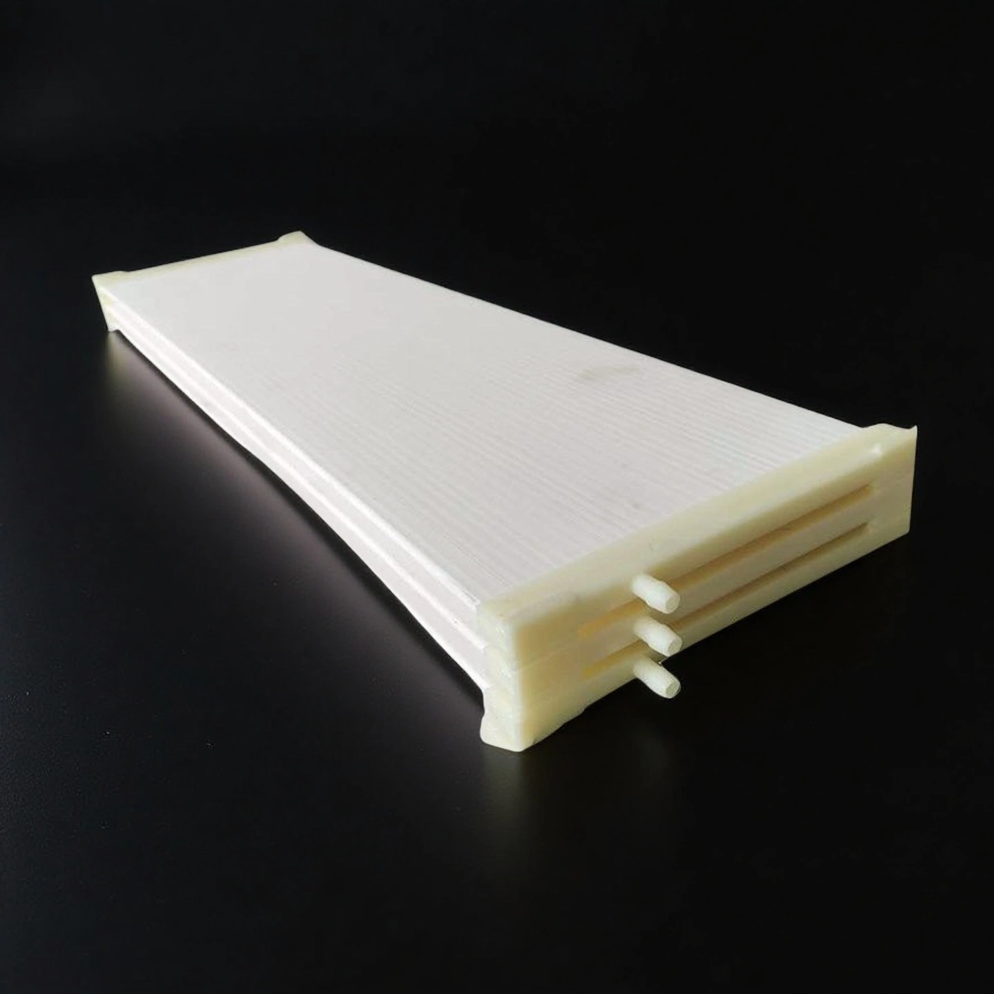
Alumina Ceramic Filtration Module for Industrial & Process Water Treatment

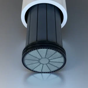
An Alumina Ceramic Filtration Module is a multichannel tubular membrane element made from high-purity alumina, designed for crossflow microfiltration and ultrafiltration of industrial, municipal and process liquids. Modules are available in several outer diameters, lengths up to typical industrial standards, and multiple channel configurations, and can be customized to match existing housings and skid layouts.

Catalog No. AT-YHL-GL001
Material ≥ 96% Al2O3
Pore Size Options 20nm – 200nm
Operating Temperature  ≤1200°C
Operating pH range pH 2–12 (short-term cleaning pH 0–14)
Engineering RFQ Review
Small-Batch Custom Support
Factory-Direct Manufacturing
Drawing & Process Review

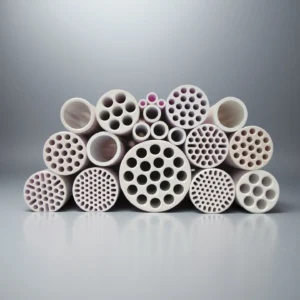
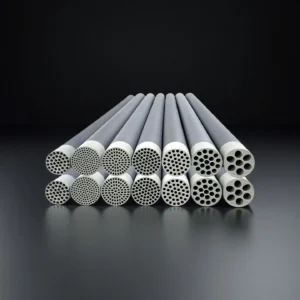
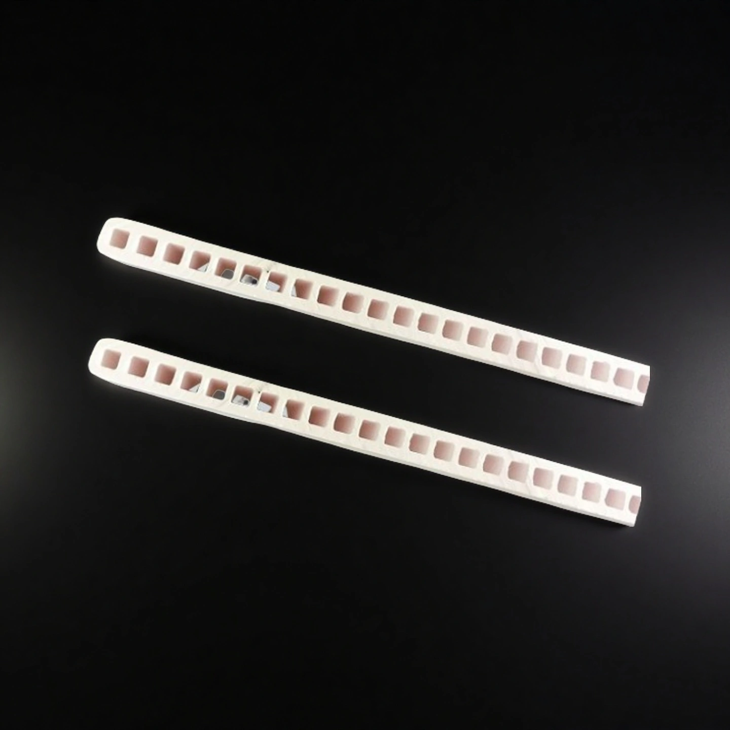
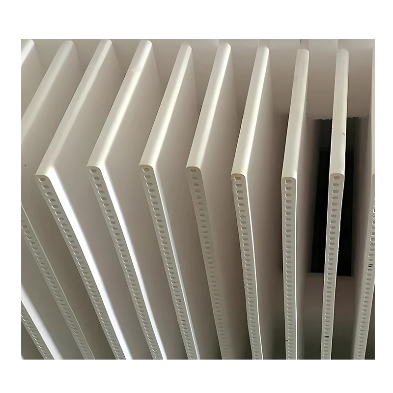
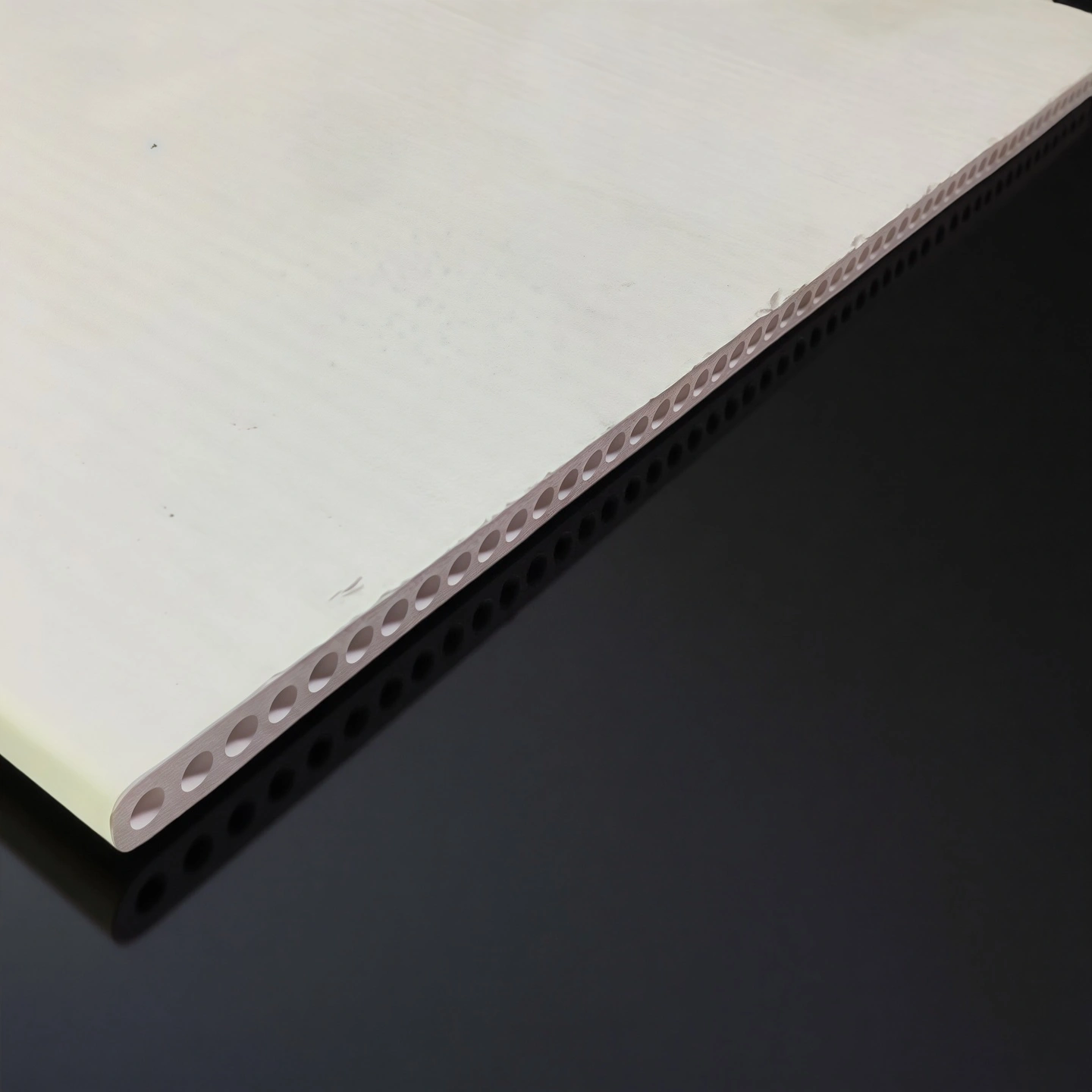
An alumina ceramic filtration module is a multichannel tubular membrane element made from ≥96% Al₂O₃, loaded into a stainless-steel housing to form a module for crossflow microfiltration (MF) and ultrafiltration (UF) of liquids. The element has parallel honeycomb channels; feed flows through the channels while clean permeate passes through the porous ceramic wall, retaining solids, oil or colloids. It is a membrane element/module.

Alumina Ceramic Filtration Module Benefits

  • Multichannel tubular design
    The module uses a multichannel alumina ceramic support to deliver a highly effective membrane area in a compact footprint, allowing higher system capacity per housing and per skid.
  • High mechanical strength under pressure and temperature cycling
    The dense alumina body tolerates repeated start–stop cycles, high crossflow velocities and frequent CIP without deformation, reducing the risk of element breakage in demanding plants.
  • Stable permeate performance in high-fouling feeds
    The ceramic membrane structure maintains stable flux in feeds containing suspended solids, oil droplets or colloids, with good flux recovery after chemical or backflush cleaning.
  • Compatibility with aggressive cleaning regimes
    The alumina membrane tolerates oxidizing agents and wide-pH cleaning sequences, enabling more intensive cleaning programs and extended operating life compared with many polymeric membranes.
  • Interface-ready module ends
    End designs can be supplied to match standard clamp, flange or potting arrangements, simplifying drop-in replacement of existing membrane elements in OEM or retrofit systems.

Alumina Ceramic Filtration Module Properties

Parameter Typical / Reference Value Qualification / Boundary
Material ≥96% Al₂O₃ multichannel tubular ceramic membrane Support + membrane layer
Pore size 20–200 nm Microfiltration/ultrafiltration range
Channel structure Multichannel element, e.g. 19 or 37 channels Typical element length: approximately 1 m
Membrane area & water production See the module series table Typical reference only; not guaranteed
Operating pH pH 2–12 Short-term cleaning pH 0–14
Operating temperature ≤1200°C element tolerance Actual liquid-filtration operation is near ambient temperature. High-temperature applicability must be confirmed against the housing, gaskets, seals, process liquid and cleaning conditions before publication or use.
Separation mode Crossflow MF/UF Not dead-end filtration
Data status Typical/reference values Final values are confirmed per order after engineering review.
Performance basis Pore size, flux and pH tolerance Porous-membrane performance should not be characterized using dense-body mechanical-strength or dielectric-property data.

Note: Any general alumina material-property figures are generic references for the ceramic body only. They are not certified values for this porous membrane module and must not be presented as the module’s operating limits. Pore size, flux, pH tolerance and complete-assembly compatibility are the relevant module parameters.

Aluminium Oxide Ceramic Filtration Module Specifications

Alumina Ceramic Filter
Item No. Length*Width*Height(mm) Quantities(pcs) Membrane area(㎡) Water production(m3/d) Weight(kg)
AT-YHL-GL001 300*320*1200 10 2.5 2-5 15
AT-YHL-GL002 720*570*450 34 6 7-14 32
AT-YHL-GL003 720*570*600 68 12 8-10 64
AT-YHL-GL004 920*320*1800 50 25 15-35 200
AT-YHL-GL005 1720*320*1800 100 50 3-70 310
AT-YHL-GL006 1720*720*1800 200 100 60-140 630
AT-YHL-GL007 1720*720*3250 400 200 120-280 1185

Ceramic vs Polymeric Membrane

  • Alumina ceramic modules offer higher mechanical strength, a wider pH cleaning range, better abrasion resistance and tolerance to hot/oxidizing CIP, which often means longer service life in high-fouling, oily, abrasive or wide-pH duty.
  • Polymeric elements (PVDF/PES/PP) can be a lower-cost choice for low-fouling, cost-sensitive, ambient applications. Choose based on feed, cleaning regime, temperature and pH — we'll help you compare for your stream.

Al₂O₃ Ceramic Filtration Module Packaging

  • Each Alumina Ceramic Filtration Module is wrapped in soft protective material to prevent abrasion, then fixed in a robust inner box to control movement during transport.
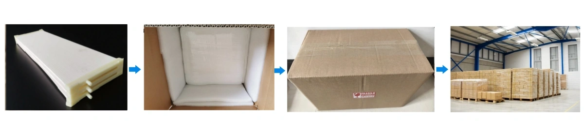
Al₂O₃ ceramic filtration module packaging

Alumina Ceramic Filtration Module Applications

ADCERAX supplies multichannel alumina ceramic membrane elements and filtration modules for OEM equipment, new filtration projects, replacement and retrofit requirements. Find your process below to see what we can review for your feed, housing and separation target.

1. Crossflow Skid OEMs and Module Integrators

For membrane-system manufacturers, skid builders and process-equipment integrators developing a new crossflow filtration unit or adapting an existing module layout.

Typical requirements

  • Multichannel tubular ceramic membrane elements
  • Standard or drawing-based module dimensions
  • Specific membrane area and channel configuration
  • Housing, end-seal and process-connection compatibility
  • OEM replacement or project-specific module configuration

What ADCERAX can review

Element dimensions, channel geometry, nominal pore size, module quantity, membrane area, housing interface, end seals and connection requirements.

Send us: skid layout, housing drawing, required flow, feed data, target separation, operating conditions and CIP plan.

2. Industrial Wastewater and Water-Reuse Projects

For wastewater-treatment EPCs, reuse-system integrators and industrial plants evaluating ceramic crossflow filtration for clarification, pretreatment or solids removal.

Typical feed streams

  • Industrial wastewater containing suspended solids or colloids
  • Biological-treatment effluent requiring further clarification
  • Process water prepared for reuse or downstream treatment
  • Variable feed streams requiring repeated backwash or CIP review

Possible process positions

  • Clarification before RO or NF
  • Pretreatment before evaporation or concentration
  • Process-water recovery and reuse
  • Suspended-solids separation before downstream polishing

Send us: feed analysis, TSS, oil content, viscosity, required permeate quality, flow demand, pH, temperature, pressure and cleaning chemicals.

3. Oily Wastewater and High-Fouling Process Liquids

For equipment manufacturers and treatment plants handling liquids containing dispersed oil, fine solids, colloids or other components that may cause rapid fouling in conventional filtration equipment.

Typical projects

  • Machining and metalworking wastewater
  • Oil-containing industrial process water
  • Parts-washing and surface-treatment wastewater
  • High-solids or high-fouling liquid clarification

What ADCERAX can review

Nominal pore-size range, channel geometry, crossflow configuration, membrane area, element dimensions, cleaning compatibility and integration with the proposed housing.

Send us: free and emulsified oil content, solids loading, particle-size distribution, viscosity, surfactants, temperature, target permeate and the proposed cleaning method.

4. Chemical, Pigment and Battery-Material Slurries

For chemical-process equipment suppliers and battery-material production lines evaluating ceramic membrane elements for clarification, concentration, washing or product-recovery steps.

Typical process streams

  • Pigment and inorganic-filler suspensions
  • Battery-material washing or clarification liquids
  • Catalyst-containing process streams
  • Abrasive or chemically demanding slurries
  • Process liquids requiring repeated chemical cleaning

Engineering review focuses

Particle-size distribution, solids concentration, liquid chemistry, viscosity, target retention, nominal pore size, channel size, seals, housing material and CIP conditions.

Send us: representative feed information, solids concentration, particle size, chemical composition, operating pH and temperature, cleaning chemicals, quantity and project stage.

Alumina Ceramic Filtration Module Usage Instructions

  • Installation

    1. Inspect each Alumina Ceramic Filtration Module for damage before installation; handle it by the ends and avoid touching the channels.
    2. Use clean gloves to prevent contamination of the sealing surfaces.
    3. Confirm that the housing and gaskets match the specified end geometry; do not force misaligned modules into the housing.
    4. Tighten clamps or flanges evenly and crosswise to avoid point loading.

  • Operation

    1. Start at low feed flow and low transmembrane pressure, then increase gradually to the approved operating conditions.
    2. Monitor permeate flow, feed pressure and differential pressure as the operating baseline.
    3. Avoid sudden valve closures, pump trips and pressure surges; use controlled start-up and shutdown sequences.

  • Cleaning & Maintenance

    1. Set the backwash frequency and duration according to the feed and system design.
    2. Follow an approved CIP program for organic fouling, inorganic scaling or other identified contaminants.
    3. Confirm chemical compatibility with the housing, gaskets and seals, then rinse thoroughly after each CIP step.
    4. Periodically perform a standardized water-flux test to monitor cleaning recovery.

  • Storage

    1. For short-term storage, keep modules clean, dry and protected from impact and freezing.
    2. For long shutdowns, drain and preserve modules according to the approved site procedure; do not leave contaminated water stagnant inside.

  • Points to Watch & Typical Misuse

    1. Problem: Over-tightened clamps crack the module ends
    Symptom: Hairline cracks or chips appear near the end faces.
    Solution: Check the gasket design and use the approved torque and cross-tightening sequence.

    2. Problem: Pressure surges damage the channels
    Symptom: Permeate loss or abnormal blockage appears after start-up.
    Solution: Start pumps gradually, open valves slowly and use surge-control measures where required.

    3. Problem: Incomplete cleaning causes progressive flux decline
    Symptom: Each CIP restores less flux and transmembrane pressure rises faster.
    Solution: Review the CIP chemistry, concentration, temperature, duration and sequence under an approved procedure.

Alumina Filtration Module FAQ

  1. Q: What is an Alumina Ceramic Filtration Module used for?
    A: An Alumina Ceramic Filtration Module is used for crossflow microfiltration and ultrafiltration of industrial wastewater, municipal effluent, chemical process liquids and food or beverage streams where robust performance and frequent cleaning are required.
  2. Q: How does an Alumina Ceramic Filtration Module differ from a polymeric membrane element?
    A: Compared with many polymeric elements, an Alumina Ceramic Filtration Module offers higher mechanical strength, tolerance to a broader pH cleaning range and better resistance to abrasion, which often results in longer service life under severe operating conditions.
  3. Q: Which pore sizes are available for Alumina Ceramic Filtration Modules?
    A: Alumina ceramic filtration modules are offered in the microfiltration/ultrafiltration range, typically around 20–200 nm nominal pore size, with the target separation (MWCO or particle size) confirmed against your feed by pilot or testing. Other grades may be available for specific clarification tasks.
  4. Q: Can Alumina Ceramic Filtration Modules handle high-temperature cleaning?
    A: Yes, the alumina ceramic structure allows Alumina Ceramic Filtration Modules to withstand elevated cleaning temperatures when system gaskets and housings are compatible, making them suitable for hot alkaline and oxidizing CIP programs.
  5. Q: Are Alumina Ceramic Filtration Modules suitable for oily wastewater or produced water?
    A: Alumina Ceramic Filtration Modules are often selected for oily wastewater and produced water applications because the ceramic surface tolerates fouling and aggressive cleaning better than many organic membranes in these feeds.
  6. Q: Can Alumina Ceramic Filtration Modules be installed in existing housings?
    A: Many projects use custom end-face designs so that the Alumina Ceramic Filtration Module can fit into existing stainless-steel or FRP housings, allowing stepwise retrofit from polymeric to ceramic technology without redesigning the entire skid.
  7. Q: What are the pH, temperature and CIP limits?
    A: Modules typically operate at pH 2–12, with short-term cleaning down to pH 0–14, and the element tolerates elevated CIP temperatures (up to ≤1200 °C material tolerance) — but actual limits depend on your housing, gaskets and seals, which must be compatible. Liquid filtration itself runs near ambient; the high-temperature figure is a material/CIP tolerance, not an operating requirement. We confirm safe pH/temperature/CIP windows during engineering review and do not guarantee a fixed flux without your feed data.
customize size

Custom Manufacturing Capabilities for Alumina Ceramic Filtration Module

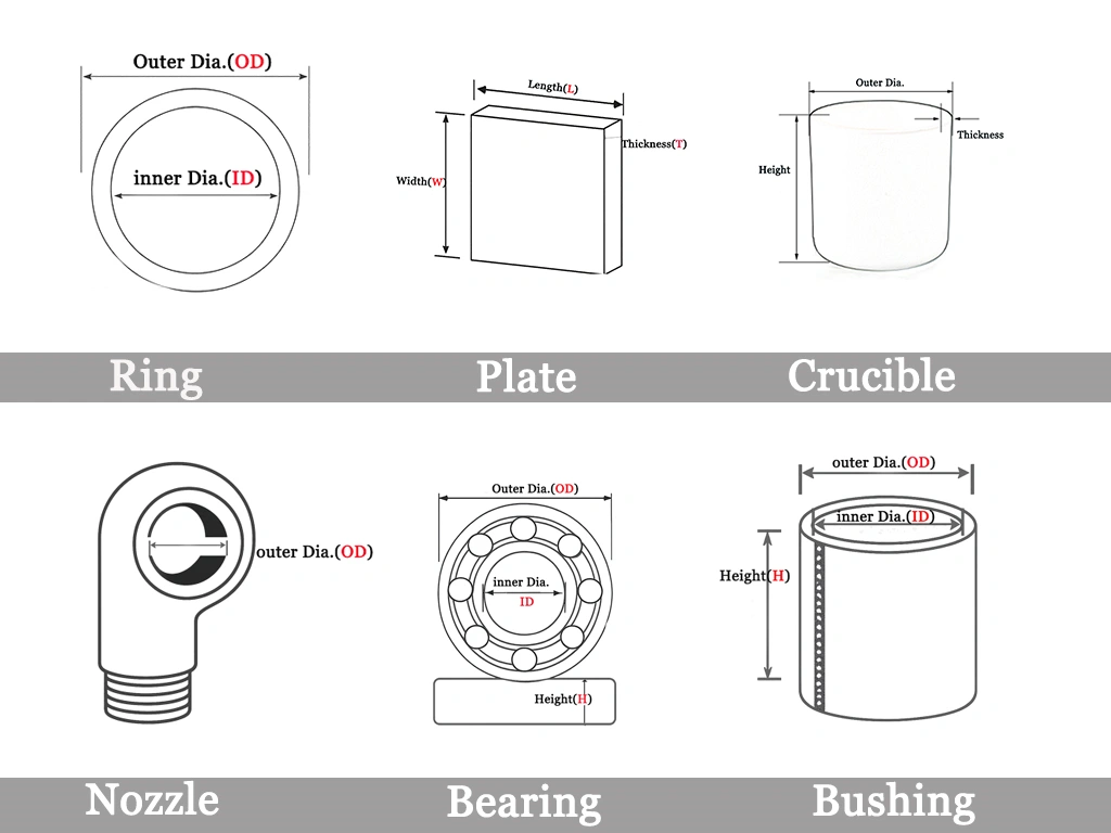
We supply Alumina Ceramic Filtration Modules in standard dimensions and as drawing-based custom elements so that OEMs and end users can align membrane geometry, hydraulics and connections with their existing or new systems.

1. Geometry & Dimensions

  • Outer diameter options suited for compact skids or high-area housings
  • Custom overall lengths for horizontal and vertical filtration racks
  • Multiple channel counts (7/19/37/61+) to match hydraulic design
  • Channel diameter selection to optimize shear rate and pressure drop
  • Wall thickness and support-body density are adjustable for strength or flow performance

2. Membrane & Performance Parameters

  • Nominal pore size or MF/UF cut-off tailored to solids, oil or colloid removal
  • Target design flux range based on feed viscosity and expected fouling load
  • Crossflow velocity window aligned with your pump curve and piping layout
  • Optional surface modification for enhanced hydrophilicity or fouling resistance
  • Calibration of membrane area per module to reach a specific skid throughput

3. End Connections & Sealing

  • End-face machining compatible with standard stainless-steel or FRP housings
  • Custom gasket grooves, O-ring dimensions and compression depths
  • End configurations: flat, spigot, socket, stepped or custom flange profiles
  • Optional protective end caps or reinforced ferrules for high-pressure duties
  • Orientation marks to ensure correct flow direction during installation

4. Surface & Structural Options

  • Support finishes: as-fired, ground, polished or low-roughness interface
  • Reinforced structural design for high-pressure or high-velocity crossflow
  • Identification features such as coding, laser marking or traceability labels
  • Optional permeate-side polishing to improve sealing and assembly alignment
  • Material tuning—including grain size and density profile—to balance permeability and strength

Related Products

ADCERAX - Your Trusted Advanced Ceramics Manufacturing Partner

Direct factory manufacturing with comprehensive ceramic materials expertise and global supply capabilities

China-Based Manufacturer

ADCERAX supplies ceramic components for overseas OEMs, equipment builders, and labs.

Custom Drawing Support

We review drawings, dimensions, materials, and application conditions before quotation.

Ceramic Process Control

Forming, sintering, machining, grinding, and finishing are arranged by part requirements.

Pre-Shipment Inspection

Dimensional checks, visual inspection, and packaging review help reduce procurement risk.

Get in Touch with Us

Our team will be happy to respond to you in less than 24 hours.

Pingxiang Factory — Silicon carbide, silicon nitride, high-temperature ceramics

Quick Quotation

*Our team will answer your inquiries within 24 hours.

*Your information will be kept strictly confidential.

Ready to Solve Your Engineering Challenge?

Partner with ADCERAX for reliable, high-performance advanced ceramic solutions. Our engineers are ready to discuss your project.

E-mail

info@adcerax.com

Phone

Tel: +86-0731-84428843 WhatsApp: +86 19311583352

Response Time

Within 24 hours

An alumina ceramic filtration module is a multichannel tubular membrane element made from ≥96% Al₂O₃, loaded into a stainless-steel housing to form a module for crossflow microfiltration (MF) and ultrafiltration (UF) of liquids. The element has parallel honeycomb channels; feed flows through the channels while clean permeate passes through the porous ceramic wall, retaining solids, oil or colloids. It is a membrane element/module.

Alumina Ceramic Filtration Module Benefits

  • Multichannel tubular design
    The module uses a multichannel alumina ceramic support to deliver a highly effective membrane area in a compact footprint, allowing higher system capacity per housing and per skid.
  • High mechanical strength under pressure and temperature cycling
    The dense alumina body tolerates repeated start–stop cycles, high crossflow velocities and frequent CIP without deformation, reducing the risk of element breakage in demanding plants.
  • Stable permeate performance in high-fouling feeds
    The ceramic membrane structure maintains stable flux in feeds containing suspended solids, oil droplets or colloids, with good flux recovery after chemical or backflush cleaning.
  • Compatibility with aggressive cleaning regimes
    The alumina membrane tolerates oxidizing agents and wide-pH cleaning sequences, enabling more intensive cleaning programs and extended operating life compared with many polymeric membranes.
  • Interface-ready module ends
    End designs can be supplied to match standard clamp, flange or potting arrangements, simplifying drop-in replacement of existing membrane elements in OEM or retrofit systems.

Alumina Ceramic Filtration Module Properties

Parameter Typical / Reference Value Qualification / Boundary
Material ≥96% Al₂O₃ multichannel tubular ceramic membrane Support + membrane layer
Pore size 20–200 nm Microfiltration/ultrafiltration range
Channel structure Multichannel element, e.g. 19 or 37 channels Typical element length: approximately 1 m
Membrane area & water production See the module series table Typical reference only; not guaranteed
Operating pH pH 2–12 Short-term cleaning pH 0–14
Operating temperature ≤1200°C element tolerance Actual liquid-filtration operation is near ambient temperature. High-temperature applicability must be confirmed against the housing, gaskets, seals, process liquid and cleaning conditions before publication or use.
Separation mode Crossflow MF/UF Not dead-end filtration
Data status Typical/reference values Final values are confirmed per order after engineering review.
Performance basis Pore size, flux and pH tolerance Porous-membrane performance should not be characterized using dense-body mechanical-strength or dielectric-property data.

Note: Any general alumina material-property figures are generic references for the ceramic body only. They are not certified values for this porous membrane module and must not be presented as the module’s operating limits. Pore size, flux, pH tolerance and complete-assembly compatibility are the relevant module parameters.

Aluminium Oxide Ceramic Filtration Module Specifications

Alumina Ceramic Filter
Item No. Length*Width*Height(mm) Quantities(pcs) Membrane area(㎡) Water production(m3/d) Weight(kg)
AT-YHL-GL001 300*320*1200 10 2.5 2-5 15
AT-YHL-GL002 720*570*450 34 6 7-14 32
AT-YHL-GL003 720*570*600 68 12 8-10 64
AT-YHL-GL004 920*320*1800 50 25 15-35 200
AT-YHL-GL005 1720*320*1800 100 50 3-70 310
AT-YHL-GL006 1720*720*1800 200 100 60-140 630
AT-YHL-GL007 1720*720*3250 400 200 120-280 1185

Ceramic vs Polymeric Membrane

  • Alumina ceramic modules offer higher mechanical strength, a wider pH cleaning range, better abrasion resistance and tolerance to hot/oxidizing CIP, which often means longer service life in high-fouling, oily, abrasive or wide-pH duty.
  • Polymeric elements (PVDF/PES/PP) can be a lower-cost choice for low-fouling, cost-sensitive, ambient applications. Choose based on feed, cleaning regime, temperature and pH — we'll help you compare for your stream.

Al₂O₃ Ceramic Filtration Module Packaging

  • Each Alumina Ceramic Filtration Module is wrapped in soft protective material to prevent abrasion, then fixed in a robust inner box to control movement during transport.
Al₂O₃ ceramic filtration module packaging

Quick Quote

The more details you provide, the faster we can quote.

*All inquiries are confidential.

Get Your Custom Solution

The more details you provide, the faster we can respond.

customize size

*We respond within 24 hours. All inquiries are confidential.

Download Catalog