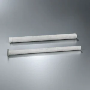
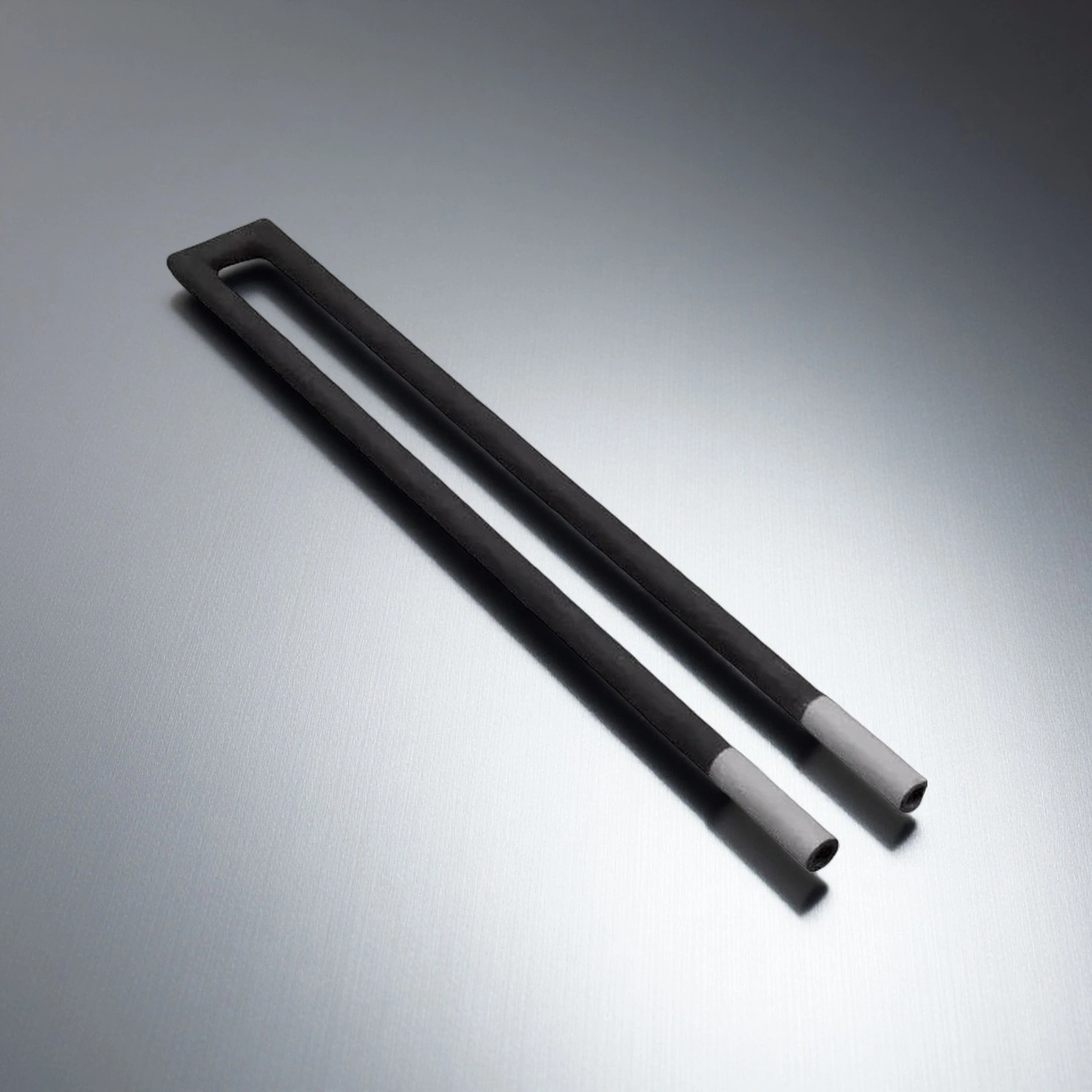
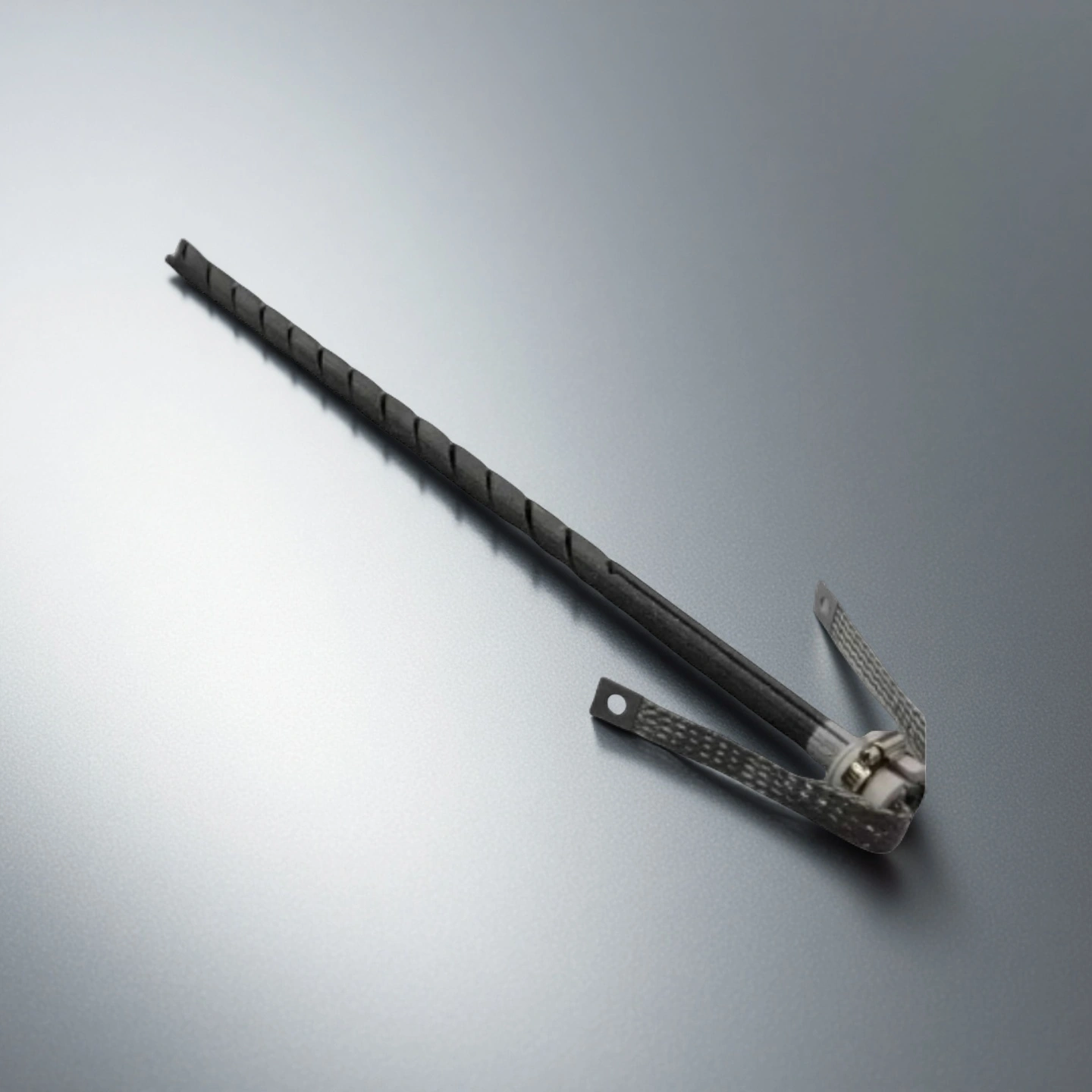
SiC Resistance-Heating Elements for Furnace Layouts
Electrical current through the designed SiC heating path generates heat in the hot zone. ADCERAX supplies spiral, straight, dumbbell, U- and W-type catalogue forms for replacement and OEM furnace projects.
Choose the form around furnace-wall access, heated length, cold-end position, terminals and circuit layout. The selected AT model and approved drawing define geometry and installation interfaces; the equipment electrical design defines the working point.
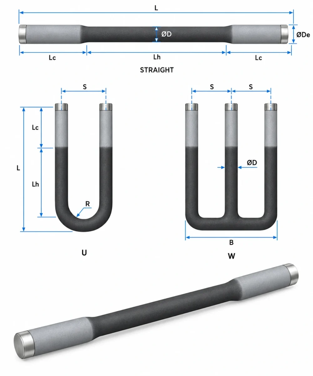
Dimensions of Silicon Carbide Heating Tube
Type 1-BA — Single-Spiral Elements
Opposite-end connections; heated zone between two cold ends
| Single Spiral Heating Type | OD / mm | Heating zone / mm | Cold zone/ mm | Overall length /mm | Hot zone surface area / cm² | voltage / V | Power / W | Range of resistance Ω (±20%) | Purity |
| AT-THG-BA001 | 14 | 200 | 200 | 600 | 87 | 59 | 1650 | 2.11 | 99% |
| AT-THG-BA002 | 14 | 200 | 250 | 700 | 87 | 60 | 1680 | 2.14 | 99% |
| AT-THG-BA003 | 14 | 250 | 200 | 650 | 109 | 71 | 1990 | 2.53 | 99% |
| AT-THG-BA004 | 14 | 250 | 250 | 750 | 109 | 73 | 2040 | 2.61 | 99% |
| AT-THG-BA005 | 14 | 300 | 250 | 800 | 131 | 85 | 2380 | 3.04 | 99% |
| AT-THG-BA006 | 16 | 200 | 250 | 700 | 100 | 58 | 1970 | 1.71 | 99% |
| AT-THG-BA007 | 16 | 250 | 200 | 650 | 125 | 69 | 2350 | 2.03 | 99% |
| AT-THG-BA008 | 16 | 250 | 250 | 750 | 125 | 70 | 2380 | 2.06 | 99% |
| AT-THG-BA009 | 16 | 250 | 300 | 850 | 125 | 71 | 2410 | 2.09 | 99% |
| AT-THG-BA010 | 16 | 300 | 200 | 700 | 150 | 81 | 2750 | 2.39 | 99% |
| AT-THG-BA011 | 16 | 300 | 250 | 800 | 150 | 82 | 2790 | 2.41 | 99% |
| AT-THG-BA012 | 16 | 300 | 300 | 900 | 150 | 83 | 2820 | 2.44 | 99% |
| AT-THG-BA013 | 16 | 350 | 250 | 850 | 175 | 94 | 3200 | 2.76 | 99% |
| AT-THG-BA014 | 16 | 350 | 300 | 950 | 175 | 95 | 3230 | 2.79 | 99% |
| AT-THG-BA015 | 20 | 300 | 400 | 1100 | 188 | 84 | 3440 | 2.05 | 99% |
| AT-THG-BA016 | 20 | 350 | 400 | 1150 | 219 | 97 | 3980 | 2.36 | 99% |
| AT-THG-BA017 | 20 | 400 | 400 | 1200 | 251 | 109 | 4470 | 2.66 | 99% |
| AT-THG-BA018 | 20 | 450 | 400 | 1250 | 282 | 121 | 4960 | 2.95 | 99% |
| AT-THG-BA019 | 25 | 300 | 400 | 1100 | 235 | 84 | 4120 | 1.71 | 99% |
| AT-THG-BA020 | 25 | 300 | 500 | 1300 | 235 | 86 | 4210 | 1.76 | 99% |
| AT-THG-BA021 | 25 | 400 | 400 | 1200 | 314 | 110 | 5390 | 2.24 | 99% |
| AT-THG-BA022 | 25 | 500 | 400 | 1300 | 392 | 135 | 6620 | 2.75 | 99% |
| AT-THG-BA023 | 30 | 300 | 400 | 1100 | 282 | 79 | 4980 | 1.25 | 99% |
| AT-THG-BA024 | 30 | 300 | 500 | 1300 | 282 | 80 | 5040 | 1.27 | 99% |
| AT-THG-BA025 | 30 | 400 | 400 | 1200 | 376 | 103 | 6490 | 1.63 | 99% |
| AT-THG-BA026 | 30 | 400 | 500 | 1400 | 376 | 104 | 6550 | 1.65 | 99% |
| AT-THG-BA027 | 30 | 500 | 400 | 1300 | 471 | 127 | 8000 | 2.02 | 99% |
| AT-THG-BA028 | 30 | 600 | 400 | 1400 | 565 | 151 | 9510 | 2.4 | 99% |
| AT-THG-BA029 | 35 | 400 | 400 | 1200 | 439 | 101 | 7680 | 1.33 | 99% |
| AT-THG-BA030 | 35 | 400 | 500 | 1400 | 439 | 102 | 7750 | 1.34 | 99% |
| AT-THG-BA031 | 35 | 500 | 400 | 1300 | 549 | 124 | 9420 | 1.63 | 99% |
| AT-THG-BA032 | 35 | 500 | 500 | 1500 | 549 | 125 | 9500 | 1.64 | 99% |
| AT-THG-BA033 | 35 | 600 | 400 | 1400 | 659 | 148 | 11200 | 1.96 | 99% |
| AT-THG-BA034 | 35 | 700 | 400 | 1500 | 769 | 171 | 13000 | 2.25 | 99% |
| AT-THG-BA035 | 40 | 500 | 400 | 1300 | 628 | 116 | 10700 | 1.26 | 99% |
| AT-THG-BA036 | 40 | 500 | 500 | 1500 | 628 | 117 | 10800 | 1.27 | 99% |
| AT-THG-BA037 | 40 | 600 | 400 | 1400 | 753 | 138 | 12700 | 1.5 | 99% |
| AT-THG-BA038 | 40 | 700 | 400 | 1500 | 879 | 161 | 14800 | 1.75 | 99% |
| AT-THG-BA039 | 45 | 700 | 450 | 1600 | 989 | 149 | 16800 | 1.32 | 99% |
| AT-THG-BA040 | 45 | 800 | 400 | 1600 | 1130 | 168 | 19000 | 1.49 | 99% |
Type 2-BB — Double-Spiral Elements
Same-end connections; paired hot- and cold-zone lengths
| Double Spiral Heating Type | OD (mm) | Heat zone (mm) | Cold zone (mm) | Overall length (mm) | Heating zone (cm²) | voltage (V) | Power (W) | Range of resistance Ω (±20%) | Purity |
| AT-THG-BB001 | 16 | 100 | 150 | 250 | 50 | 61 | 940 | 3.96 | 99% |
| AT-THG-BB002 | 16 | 100 | 200 | 300 | 50 | 69 | 1060 | 4.49 | 99% |
| AT-THG-BB003 | 16 | 150 | 150 | 300 | 75 | 84 | 1290 | 5.47 | 99% |
| AT-THG-BB004 | 16 | 150 | 250 | 400 | 75 | 99 | 1520 | 6.45 | 99% |
| AT-THG-BB005 | 16 | 200 | 200 | 400 | 100 | 113 | 1740 | 7.34 | 99% |
| AT-THG-BB006 | 16 | 250 | 200 | 450 | 125 | 135 | 2080 | 8.76 | 99% |
| AT-THG-BB007 | 20 | 100 | 150 | 250 | 62 | 58 | 1110 | 3.03 | 99% |
| AT-THG-BB008 | 20 | 100 | 250 | 350 | 62 | 72 | 1380 | 3.76 | 99% |
| AT-THG-BB009 | 20 | 150 | 200 | 350 | 94 | 87 | 1670 | 4.53 | 99% |
| AT-THG-BB010 | 20 | 200 | 200 | 400 | 125 | 109 | 2090 | 5.68 | 99% |
| AT-THG-BB011 | 20 | 250 | 150 | 400 | 157 | 124 | 2380 | 6.46 | 99% |
| AT-THG-BB012 | 20 | 250 | 250 | 500 | 157 | 138 | 2650 | 7.19 | 99% |
| AT-THG-BB013 | 20 | 300 | 250 | 550 | 188 | 160 | 3070 | 8.34 | 99% |
| AT-THG-BB014 | 25 | 150 | 200 | 350 | 117 | 87 | 2000 | 3.78 | 99% |
| AT-THG-BB015 | 25 | 200 | 200 | 400 | 157 | 110 | 2530 | 4.78 | 99% |
| AT-THG-BB016 | 25 | 200 | 300 | 500 | 157 | 121 | 2780 | 5.27 | 99% |
| AT-THG-BB017 | 25 | 300 | 300 | 600 | 235 | 167 | 3840 | 7.26 | 99% |
| AT-THG-BB018 | 25 | 300 | 400 | 700 | 235 | 179 | 4120 | 7.78 | 99% |
| AT-THG-BB019 | 25 | 350 | 300 | 650 | 274 | 191 | 4390 | 8.31 | 99% |
| AT-THG-BB020 | 25 | 400 | 300 | 700 | 314 | 214 | 4920 | 9.31 | 99% |
| AT-THG-BB021 | 30 | 200 | 200 | 400 | 188 | 190 | 2790 | 2.9 | 99% |
| AT-THG-BB022 | 30 | 250 | 200 | 450 | 235 | 111 | 3440 | 3.58 | 99% |
| AT-THG-BB023 | 30 | 300 | 300 | 600 | 282 | 132 | 4090 | 4.26 | 99% |
| AT-THG-BB024 | 30 | 350 | 350 | 700 | 329 | 153 | 4740 | 4.94 | 99% |
| AT-THG-BB025 | 30 | 400 | 400 | 800 | 376 | 174 | 5390 | 5.62 | 99% |
| AT-THG-BB026 | 30 | 450 | 350 | 800 | 424 | 194 | 6010 | 6.26 | 99% |
| AT-THG-BB027 | 30 | 500 | 300 | 800 | 471 | 214 | 6630 | 6.91 | 99% |
| AT-THG-BB028 | 35 | 200 | 200 | 400 | 219 | 89 | 3260 | 2.43 | 99% |
| AT-THG-BB029 | 35 | 250 | 200 | 450 | 274 | 109 | 3990 | 2.98 | 99% |
| AT-THG-BB030 | 35 | 300 | 300 | 600 | 329 | 130 | 4760 | 3.55 | 99% |
| AT-THG-BB031 | 35 | 400 | 300 | 700 | 439 | 171 | 6260 | 4.67 | 99% |
| AT-THG-BB032 | 35 | 450 | 350 | 800 | 494 | 191 | 6990 | 5.22 | 99% |
| AT-THG-BB033 | 35 | 500 | 300 | 800 | 549 | 211 | 7720 | 5.77 | 99% |
| AT-THG-BB034 | 40 | 200 | 200 | 400 | 251 | 86 | 3660 | 2.02 | 99% |
| AT-THG-BB035 | 40 | 250 | 200 | 450 | 314 | 106 | 4510 | 2.49 | 99% |
| AT-THG-BB036 | 40 | 300 | 300 | 600 | 376 | 127 | 5400 | 2.99 | 99% |
| AT-THG-BB037 | 40 | 350 | 300 | 650 | 439 | 147 | 6250 | 3.46 | 99% |
| AT-THG-BB038 | 40 | 400 | 300 | 700 | 502 | 167 | 7100 | 3.93 | 99% |
| AT-THG-BB039 | 40 | 400 | 400 | 800 | 502 | 167 | 7100 | 3.93 | 99% |
| AT-THG-BB040 | 40 | 450 | 300 | 750 | 565 | 186 | 7910 | 4.37 | 99% |
| AT-THG-BB041 | 40 | 450 | 350 | 800 | 565 | 187 | 7950 | 4.4 | 99% |
| AT-THG-BB042 | 40 | 500 | 300 | 800 | 628 | 206 | 8760 | 4.84 | 99% |
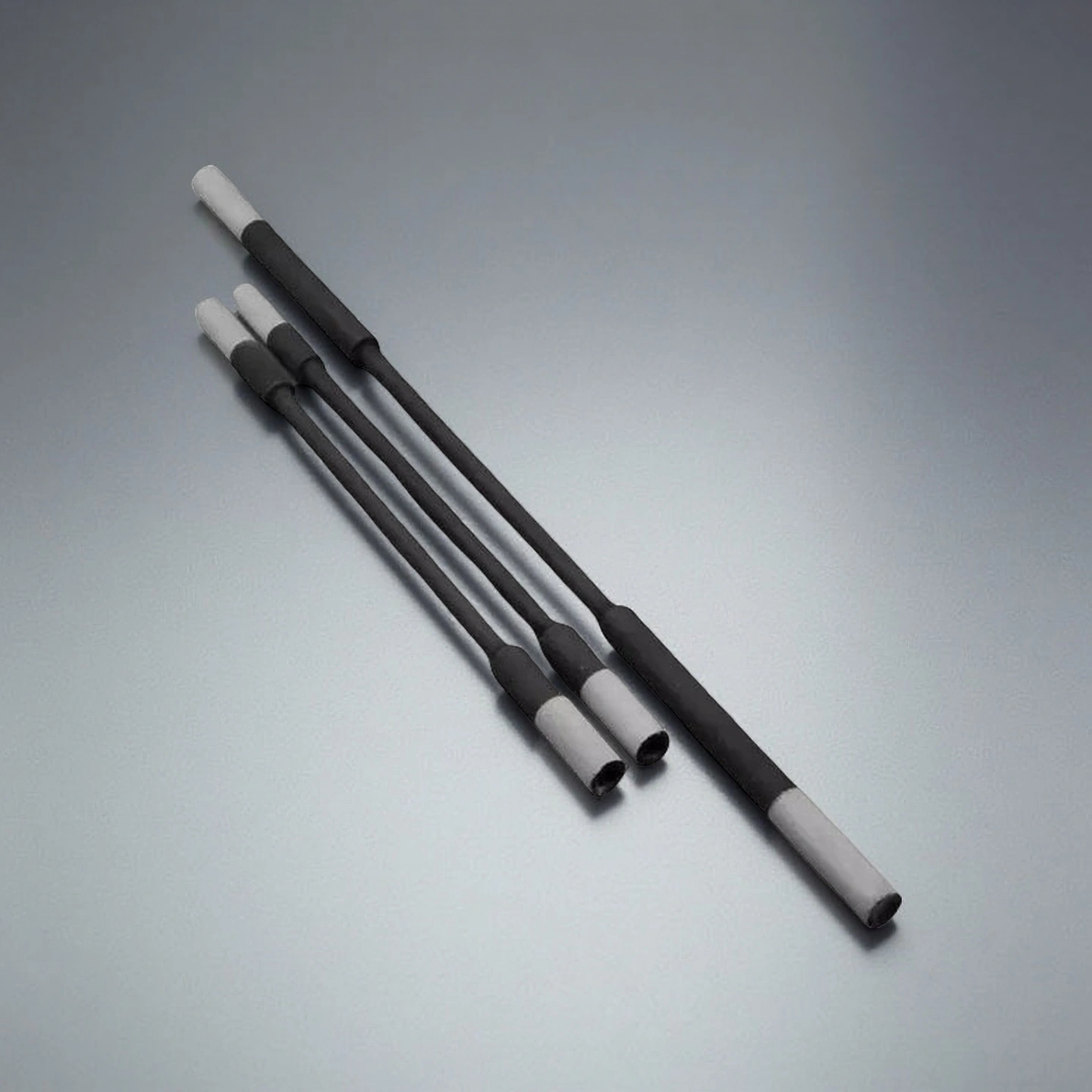
Type 3-BD — Dumbbell Elements
Enlarged ends; compare body and end diameters for mounting
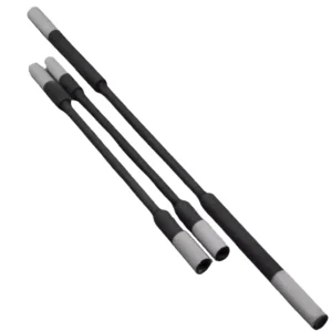
| Sic Heating Element -Rod | Small side OD / mm | Heat zone length / mm | Cold zone length / mm | large side OD / mm | Range of resistance / Ω | Purity |
| AT-THG-BD001 | 8 | 180 | 60 | 14 | 2.6-5.2 | 99% |
| AT-THG-BD002 | 8 | 180 | 150 | 14 | 2.6-5.2 | 99% |
| AT-THG-BD003 | 8 | 150 | 150 | 14 | 2.2-4.5 | 99% |
| AT-THG-BD004 | 8 | 180 | 180 | 14 | 2.6-5.2 | 99% |
| AT-THG-BD005 | 8 | 200 | 150 | 14 | 2.9-5.8 | 99% |
| AT-THG-BD006 | 12 | 150 | 200 | 20 | 1.1-2.2 | 99% |
| AT-THG-BD007 | 12 | 200 | 200 | 20 | 1.4-2.9 | 99% |
| AT-THG-BD008 | 12 | 250 | 200 | 20 | 1.8-3.8 | 99% |
| AT-THG-BD009 | 14 | 180 | 150 | 22 | 1.3-2.3 | 99% |
| AT-THG-BD010 | 14 | 150 | 250 | 22 | 0.9-1.8 | 99% |
| AT-THG-BD011 | 14 | 200 | 250 | 22 | 1.2-2.3 | 99% |
| AT-THG-BD012 | 14 | 250 | 250 | 22 | 1.5-3.0 | 99% |
| AT-THG-BD013 | 14 | 300 | 250 | 22 | 1.8-3.5 | 99% |
| AT-THG-BD014 | 14 | 400 | 350 | 22 | 2.3-4.7 | 99% |
| AT-THG-BD015 | 18 | 300 | 250 | 28 | 1.1-2.2 | 99% |
| AT-THG-BD016 | 18 | 300 | 350 | 28 | 1.1-2.2 | 99% |
| AT-THG-BD017 | 18 | 400 | 250 | 28 | 1.4-2.9 | 99% |
| AT-THG-BD018 | 18 | 500 | 350 | 28 | 1.8-3.6 | 99% |
| AT-THG-BD019 | 18 | 600 | 350 | 28 | 2.1-4.3 | 99% |
| AT-THG-BD020 | 18 | 400 | 400 | 28 | 1.4-2.9 | 99% |
| AT-THG-BD021 | 25 | 400 | 400 | 38 | 0.8-1.7 | 99% |
| AT-THG-BD022 | 25 | 600 | 500 | 38 | 1.3-2.6 | 99% |
| AT-THG-BD023 | 25 | 800 | 450 | 38 | 1.7-3.4 | 99% |
| AT-THG-BD024 | 25 | 500 | 400 | 45 | 0.6-1.2 | 99% |
| AT-THG-BD025 | 30 | 1000 | 500 | 45 | 1.1-2.2 | 99% |
| AT-THG-BD026 | 30 | 1200 | 500 | 45 | 1.3-2.6 | 99% |
| AT-THG-BD027 | 40 | 1000 | 500 | 56 | 0.8-1.7 | 99% |
| AT-THG-BD028 | 40 | 1500 | 500 | 56 | 1.3-2.6 | 99% |
| AT-THG-BD029 | 40 | 2400 | 700 | 56 | 2.0-4.0 | 99% |
| AT-THG-BD030 | 40 | 2600 | 850 | 56 | 2.2-4.4 | 99% |
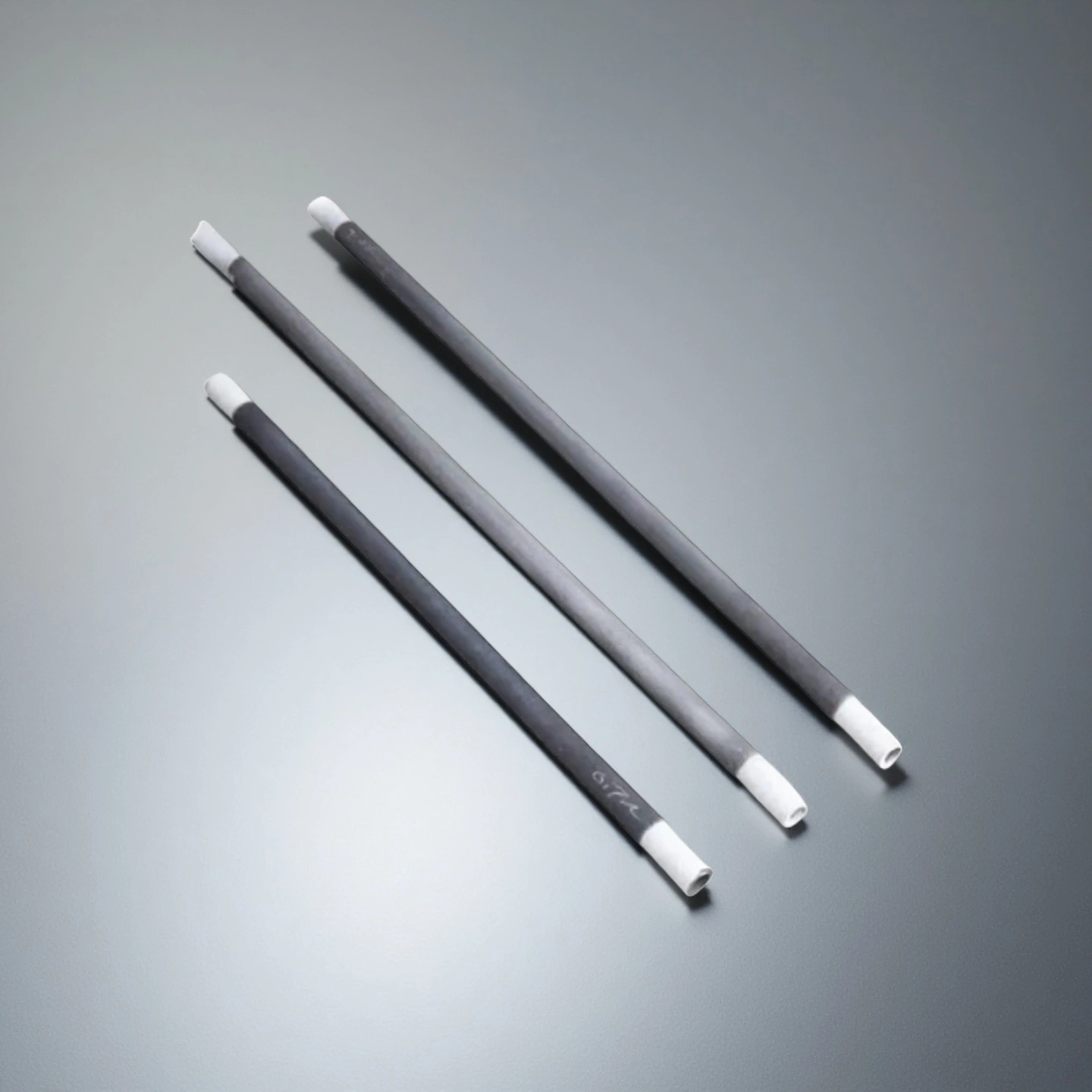
Type 4-BC — Straight Rod/Tube-Form Elements
Straight layout; compare OD and hot/cold-zone lengths
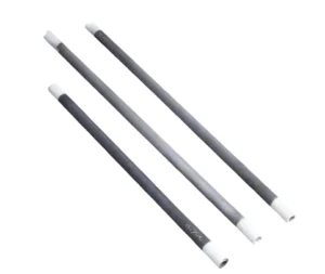
| Sic Heating Element Type | OD / mm | Heating zone length / mm | Cold zone length / mm | Range of resistance / Ω | Purity |
| AT-THG-BC001 | 14 | 200 | 250 | 1.2-1.3 | 99% |
| AT-THG-BC002 | 14 | 250 | 250 | 1.5-3.0 | 99% |
| AT-THG-BC003 | 14 | 300 | 250 | 1.8-3.5 | 99% |
| AT-THG-BC004 | 14 | 400 | 350 | 2.3-4.7 | 99% |
| AT-THG-BC005 | 14 | 500 | 350 | 2.9-5.9 | 99% |
| AT-THG-BC006 | 16 | 200 | 200 | 0.9-1.9 | 99% |
| AT-THG-BC007 | 16 | 250 | 200 | 1.2-2.4 | 99% |
| AT-THG-BC008 | 16 | 300 | 300 | 1.4-2.8 | 99% |
| AT-THG-BC009 | 18 | 250 | 250 | 0.9-1.8 | 99% |
| AT-THG-BC010 | 18 | 300 | 350 | 1.1-2.2 | 99% |
| AT-THG-BC011 | 18 | 400 | 250 | 1.4-2.9 | 99% |
| AT-THG-BC012 | 18 | 500 | 350 | 1.8-3.6 | 99% |
| AT-THG-BC013 | 20 | 200 | 200 | 0.6-1.2 | 99% |
| AT-THG-BC014 | 20 | 250 | 250 | 0.7-1.4 | 99% |
| AT-THG-BC015 | 20 | 300 | 300 | 0.8-1.6 | 99% |
| AT-THG-BC016 | 20 | 400 | 350 | 1.1-2.2 | 99% |
| AT-THG-BC017 | 20 | 500 | 400 | 1.4-2.8 | 99% |
| AT-THG-BC018 | 20 | 600 | 350 | 1.5-3.0 | 99% |
| AT-THG-BC019 | 25 | 300 | 400 | 0.6-1.3 | 99% |
| AT-THG-BC020 | 25 | 400 | 400 | 0.8-1.7 | 99% |
| AT-THG-BC021 | 25 | 500 | 400 | 1.1-2.2 | 99% |
| AT-THG-BC022 | 25 | 600 | 500 | 1.3-2.6 | 99% |
| AT-THG-BC023 | 25 | 800 | 450 | 1.7-3.4 | 99% |
| AT-THG-BC024 | 25 | 900 | 400 | 1.9-3.8 | 99% |
| AT-THG-BC025 | 25 | 1000 | 500 | 2.2-4.5 | 99% |
| AT-THG-BC026 | 30 | 400 | 400 | 0.5-0.9 | 99% |
| AT-THG-BC027 | 30 | 500 | 400 | 0.6-1.2 | 99% |
| AT-THG-BC028 | 30 | 1000 | 500 | 1.1-2.2 | 99% |
| AT-THG-BC029 | 30 | 1200 | 500 | 1.3-2.6 | 99% |
| AT-THG-BC030 | 30 | 1300 | 500 | 1.4-2.9 | 99% |
| AT-THG-BC031 | 30 | 1500 | 250 | 1.6-3.4 | 99% |
| AT-THG-BC032 | 30 | 1500 | 300 | 1.6-3.4 | 99% |
| AT-THG-BC033 | 30 | 1500 | 600 | 1.6-3.4 | 99% |
| AT-THG-BC034 | 30 | 2000 | 650 | 2.2-4.4 | 99% |
| AT-THG-BC035 | 35 | 400 | 400 | 0.4-0.8 | 99% |
| AT-THG-BC036 | 35 | 500 | 400 | 0.5-1.0 | 99% |
| AT-THG-BC037 | 35 | 1000 | 500 | 1.0-2.0 | 99% |
| AT-THG-BC038 | 35 | 1200 | 500 | 1.1-2.2 | 99% |
| AT-THG-BC039 | 35 | 1500 | 500 | 1.4-2.8 | 99% |
| AT-THG-BC040 | 40 | 400 | 400 | 0.3-0.7 | 99% |
| AT-THG-BC041 | 40 | 1000 | 500 | 0.8-1.7 | 99% |
| AT-THG-BC042 | 40 | 1500 | 500 | 1.3-2.6 | 99% |
| AT-THG-BC043 | 40 | 2000 | 650 | 1.7-3.4 | 99% |
| AT-THG-BC044 | 40 | 2400 | 700 | 2.0-4.0 | 99% |
| AT-THG-BC045 | 40 | 2600 | 850 | 2.2-4.4 | 99% |
Type 5-BF — W-Type Three-Leg Elements
Three legs; compare centre distance and bridge dimensions
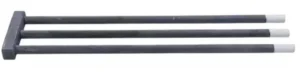
| Three Phase Type | Heat zone OD / mm | Heating zone length / mm | Cold zone Length / mm | center distance / mm | Bridge OD / mm | Overall length / mm | Purity |
| AT-THG-BF001 | 14 | 200 | 250 | 40 | 14 | 54 | 99% |
| AT-THG-BF002 | 14 | 250 | 300 | 50 | 14 | 64 | 99% |
| AT-THG-BF003 | 14 | 300 | 350 | 60 | 14 | 74 | 99% |
| AT-THG-BF004 | 16 | 200 | 250 | 40 | 16 | 56 | 99% |
| AT-THG-BF005 | 16 | 250 | 300 | 50 | 16 | 66 | 99% |
| AT-THG-BF006 | 16 | 300 | 350 | 60 | 16 | 76 | 99% |
| AT-THG-BF007 | 18 | 300 | 350 | 60 | 18 | 78 | 99% |
| AT-THG-BF008 | 18 | 400 | 400 | 70 | 18 | 88 | 99% |
| AT-THG-BF009 | 18 | 500 | 450 | 75 | 18 | 93 | 99% |
| AT-THG-BF010 | 20 | 250 | 300 | 50 | 20 | 70 | 99% |
| AT-THG-BF011 | 20 | 300 | 350 | 60 | 20 | 80 | 99% |
| AT-THG-BF012 | 20 | 400 | 400 | 70 | 20 | 90 | 99% |
| AT-THG-BF013 | 25 | 400 | 400 | 70 | 25 | 95 | 99% |
| AT-THG-BF014 | 25 | 500 | 450 | 75 | 25 | 100 | 99% |
| AT-THG-BF015 | 25 | 600 | 500 | 80 | 25 | 105 | 99% |
| AT-THG-BF016 | 30 | 600 | 400 | 70 | 30 | 100 | 99% |
| AT-THG-BF017 | 30 | 700 | 450 | 75 | 30 | 105 | 99% |
| AT-THG-BF018 | 30 | 800 | 500 | 80 | 30 | 110 | 99% |
Type 6-BU — U-Type Two-Leg Elements
Two legs; compare centre distance and bridge dimensions
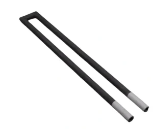
| U-type Heating Elements | Heating zone OD / mm | Heating zone Length / mm | Cold zone Length / mm | center distance / mm | Bridge OD / mm | Overall length / mm | Range of resistance / Ω | Purity |
| AT-THG-BU001 | 14 | 200 | 250 | 40 | 14 | 54 | 2.4-4.6 | 99% |
| AT-THG-BU002 | 14 | 250 | 300 | 50 | 14 | 64 | 3.0-6.0 | 99% |
| AT-THG-BU003 | 14 | 300 | 350 | 60 | 14 | 74 | 3.6-7.0 | 99% |
| AT-THG-BU004 | 16 | 200 | 250 | 40 | 16 | 56 | 1.4-2.8 | 99% |
| AT-THG-BU005 | 16 | 250 | 300 | 50 | 16 | 66 | 1.8-3.6 | 99% |
| AT-THG-BU006 | 16 | 300 | 350 | 60 | 16 | 76 | 2.0-5.0 | 99% |
| AT-THG-BU007 | 18 | 300 | 350 | 60 | 18 | 78 | 2.0-5.0 | 99% |
| AT-THG-BU008 | 18 | 400 | 400 | 70 | 18 | 88 | 2.8-5.8 | 99% |
| AT-THG-BU009 | 18 | 500 | 450 | 75 | 18 | 93 | 3.6-7.2 | 99% |
| AT-THG-BU010 | 20 | 250 | 300 | 50 | 20 | 70 | 1.8-3.6 | 99% |
| AT-THG-BU011 | 20 | 300 | 350 | 60 | 20 | 80 | 2.0-5.0 | 99% |
| AT-THG-BU012 | 20 | 400 | 400 | 70 | 20 | 90 | 2.8-5.8 | 99% |
| AT-THG-BU013 | 25 | 400 | 400 | 70 | 25 | 95 | 1.6-3.4 | 99% |
| AT-THG-BU014 | 25 | 500 | 450 | 75 | 25 | 100 | 2.2-4.4 | 99% |
| AT-THG-BU015 | 25 | 600 | 500 | 80 | 25 | 105 | 2.6-5.2 | 99% |
| AT-THG-BU016 | 30 | 600 | 400 | 70 | 30 | 100 | 1.4-2.8 | 99% |
| AT-THG-BU017 | 30 | 700 | 450 | 75 | 30 | 105 | 1.6-3.2 | 99% |
| AT-THG-BU018 | 30 | 800 | 500 | 80 | 30 | 110 | 1.8-3.6 | 99% |
Download the Product Catalogue
How SiC Heating Element Bodies Differ
Silicon carbide heating element bodies are not all made the same way. Suppliers describe bodies formed and densified by different routes, and the route can influence porosity, surface condition and how the body behaves in a particular furnace atmosphere. When comparing suppliers or replacing an element, treat the body description as one part of the specification alongside the drawing, the resistance measurement condition and the furnace duty — not as the only deciding factor.
Ask what route and material specification the supplied element uses, and confirm it against the drawing revision and the acceptance criteria agreed for your furnace. Catalogue references support comparison; the selected drawing defines what is actually supplied.
Silicon Carbide Heating Element Failure Modes to Check
When deciding whether to keep or replace a silicon carbide heating element, check the patterns below rather than a single number.
| Pattern to check | What it can indicate |
|---|---|
| Resistance higher than the recorded value under the same measurement condition | Normal ageing of the element over service time |
| Localised hot or bright zone on the body | Non-uniform loading or a developing weak section |
| Surface deposits, discolouration or material loss | Atmosphere or contaminant attack on the body |
| Worn, loose or heated terminals and connections | Connection ageing or poor contact at the element ends |
| Cracks at the body, ends or bridge after cycling | Mechanical or thermal-cycling stress |
*Record resistance, appearance and connection condition against the equipment service plan, and review a suspected element with the equipment engineer before replacing it within a group. Exact replacement timing depends on the furnace duty and acceptance criteria for that installation.
Packaging Method of Silicon Carbide Heating Tube
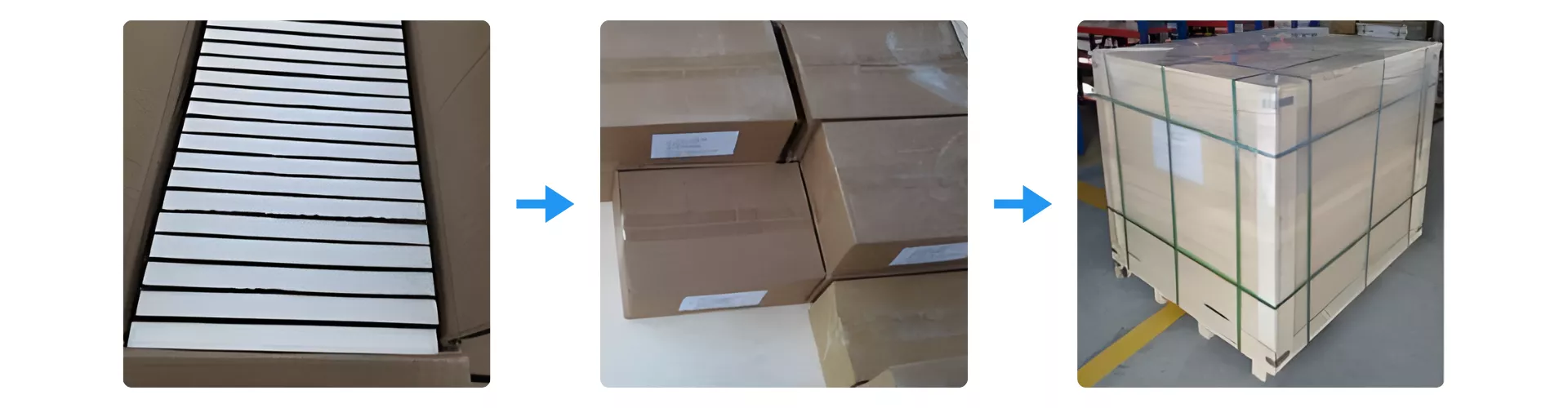
Protective inner cartons, outer boxes and pallet wrapping illustrate packaging options. The order-specific plan accounts for element shape, terminals, bridge features, quantity and transport route.
At receipt, inspect packaging and accessible bodies, ends and connections, then record any concern against the agreed inspection and acceptance requirements.