What a Silicon Carbide Liner Tube Is
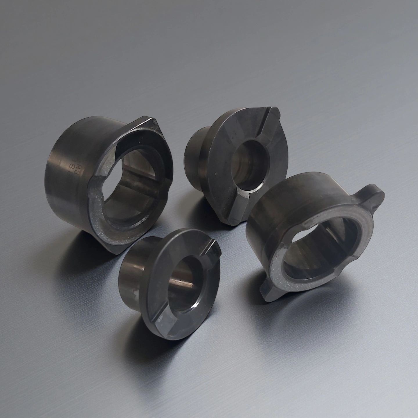
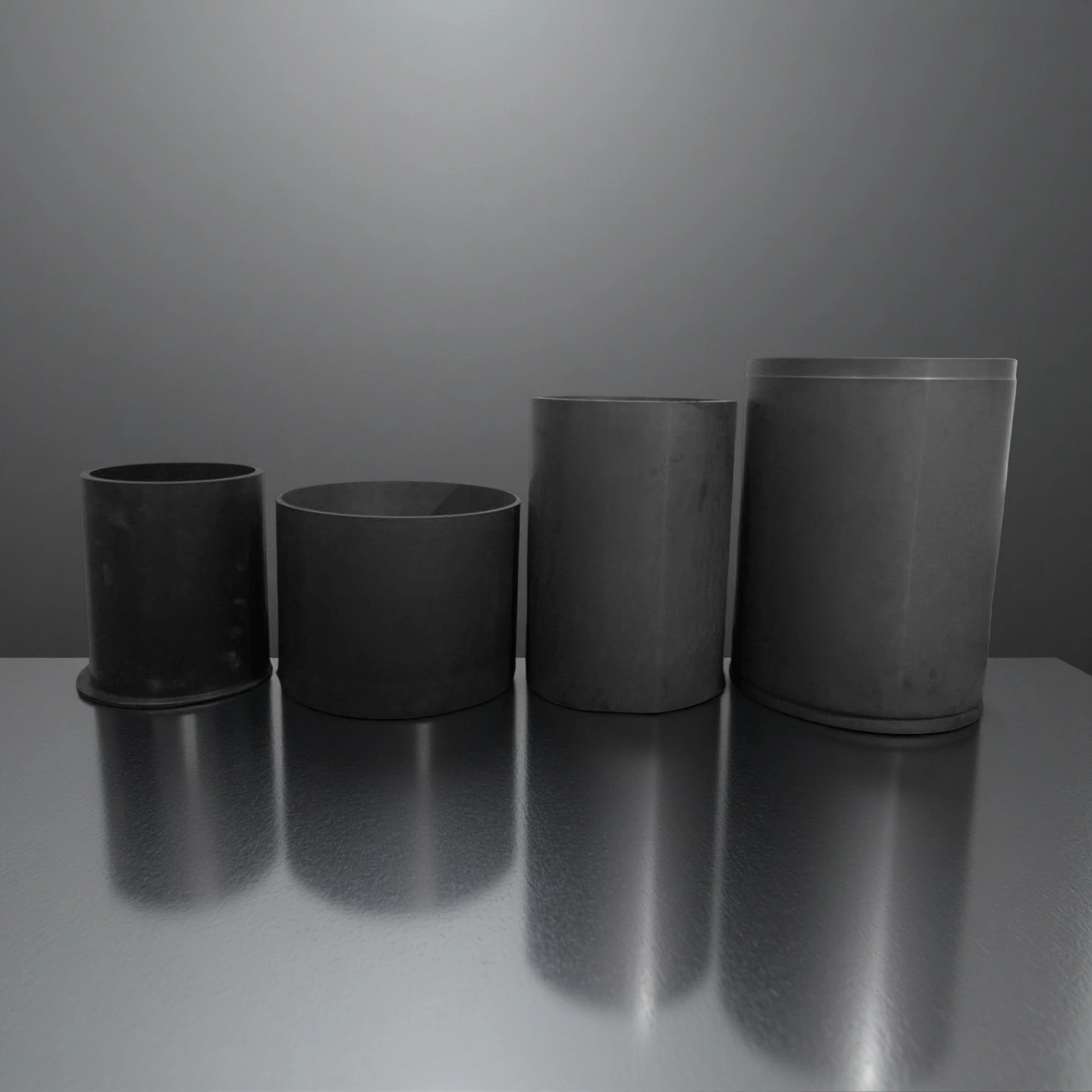
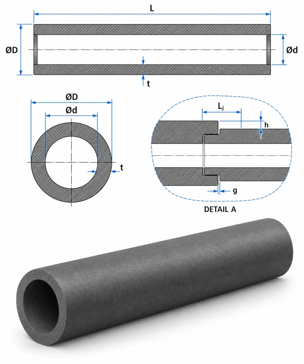
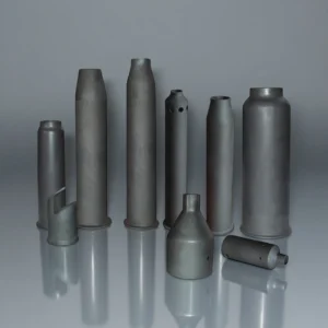
A silicon carbide liner tube is a ceramic wear component installed inside a pipe, housing, elbow, tee or other conveying channel. It can also be supplied as a standalone liner section. Its role is to take the abrasion and impact of the moving medium so the steel or metal body behind it stays protected. It is not a structural tube, a heat exchanger tube, a furnace tube, a thermocouple protection tube, or a complete design proof for a pressure pipeline.
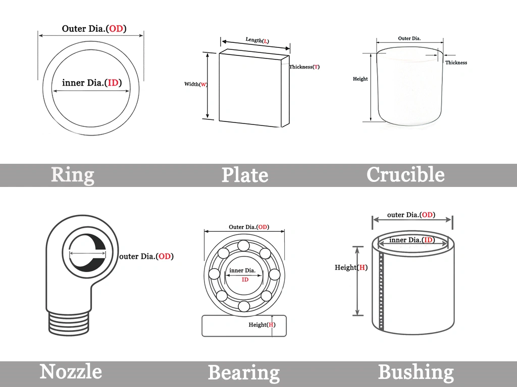
Dimensions of Silicon Carbide Liner Tube
|
SiC Liner |
|
Item No. |
Diameter(mm) |
Height (mm) |
|
AT-SIC-TT1001 |
Customize |
↓Download the Product Catalogue
Performance: Compare SiC Material Routes for the Liner
RBSiC/SiSiC is a reaction-bonded route with nominal residual silicon. SSiC is a pressureless-sintered route with higher SiC content. Select the route against the process medium, temperature, wear exposure and the component drawing.
| Material-level property |
RBSiC / SiSiC |
SSiC |
| SiC content (wt%) |
85 nominal |
≥99 |
| Route and residual silicon |
Reaction-bonded; 15 wt% residual free silicon nominal |
Pressureless-sintered SiC |
| Bulk density (g/cm³) |
≥3.02 |
3.10 typical |
| Apparent open porosity (vol%) |
≤0.1 |
<0.1 |
| Flexural strength (MPa) |
250 at 20°C |
380; compare with a stated test temperature |
| Young's modulus (GPa) |
330 at 20°C |
420; compare with a stated test temperature |
| Thermal conductivity (W/(m·K)) |
45 at 1200°C |
100–120 at room temperature |
| Application-temperature ceiling (°C) |
1380 |
1600 |
How to Choose a Silicon Carbide Liner Tube
Three decisions carry most of the specification work. Each one is compared against a real process condition rather than a generic rating.
| Decision |
Compare |
Why it matters |
| Wear mechanism |
Particle size, hardness and shape; solids loading, velocity and impact location |
Locate the exposed surface and the expected wear pattern |
| Flow-path interface |
Bore transitions, end alignment, joints and support |
Keep the ceramic working face aligned with the receiving equipment |
| Sample acceptance |
Current-part failure mode, inspection method and an application-relevant trial |
Compare candidate liners under agreed conditions |
Common Failure Modes to Check in the Field
Silicon carbide liner tubes are hard and wear slowly under sliding abrasion. In service, the failures buyers report are usually not bulk wear but local mechanisms, so the inspection plan should look for these first:
- Perforation or local thinning at the impact zone — typically the elbow outer arc, tee, reducer, inlet, behind a valve or a rough joint.
- Cracking or chipping at edges, ends and steps where impact angle is high.
- Joint erosion — the gap itself is attacked once the medium finds a path.
- Debonding or hollow spots where the joining layer has failed behind the liner.
- Liner rotation or shifting when location and support allow movement.
- Substrate corrosion or leakage once the protective ceramic is breached.
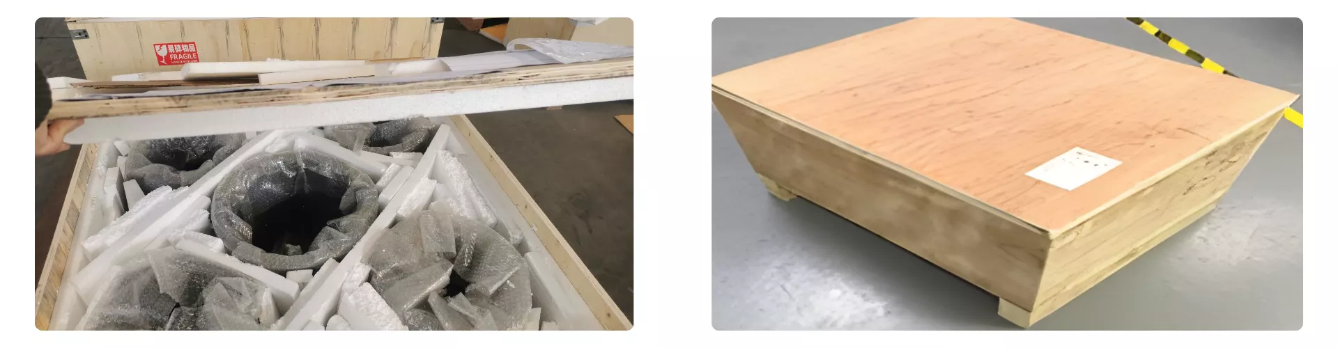
Protective Packaging for Silicon Carbide Liner Tube
Protective cushioning, separated placement and wooden crates illustrate packaging options. Plan support and protection around the agreed liner geometry, ends, edges, quantity and shipping route.
At receipt, inspect the package and the accessible ceramic surfaces, then record chips, cracks or dimensional concerns against the order's acceptance criteria.
Application Review for Custom SiC Liners
These conditions guide the material-route review, the liner geometry and an application-relevant sample test.
- Mineral slurry and solids transport: Solids loading, particle size and hardness, velocity, impact location and the existing wear pattern determine which SiC liner route, bore design and wall thickness will give the service life you need. The review compares the actual abrasive medium with the proposed liner specification, then defines trial acceptance criteria around local thickness loss, joint condition and attachment state over a defined throughput.Silicon Carbide Liner Tube in Chloride-Rich and Acidic Transfer Loops of Chemical Production Units
- Chemical-process flow paths: Media composition, concentration, temperature, contaminants and cleaning exposure set the material-route selection and surface-finish requirements. Silicon carbide liner tubes in these environments are reviewed against the actual process chemistry rather than a generic corrosion rating, with particular attention to thermal cycling, residual-layer formation and long-term dimensional stability under operating conditions.
- Pulp, paper and related streams: Actual liquor or suspension chemistry, entrained solids, temperature and installation position define the liner's wear-facing surface, joint design and support method. These applications often combine chemical exposure with moderate abrasion, so the review confirms that the selected SiC material route and liner geometry address both mechanisms across the expected service window.
Installation and Service of the Silicon Carbide Liner Tube
Silicon Carbide Liner Tube is best utilized when operators follow stable installation, handling, and operational practices that preserve its mechanical integrity, ensure predictable performance, and extend service cycles under abrasive, corrosive, and high-temperature conditions.
-
Before fitting
1. Qualified personnel isolate the equipment and compare liner identity, drawing revision and inspection records.
2. The receiving bore, alignment features and mating surfaces are cleaned and inspected before the liner is brought to the installation position.
-
Mechanical interface
1. Match receiving bore, alignment, supports, joints, locating layer, end transitions and thermal-movement allowance.
2. Silicon carbide liner tubes are hard and brittle, so handling procedures avoid impact and point loading.
3. The liner is positioned so its wear-facing surface aligns with the flow path and its ends mate cleanly with adjacent sections or the equipment body.
4. Joint gaps, support contact and any locating or bonding layer thickness are checked against the drawing before final assembly.
-
Return to service
1. Complete the equipment owner's approved assembly, sealing and operating checks.
2. Startup procedures follow the equipment's operating manual, with attention to flow rate, pressure, temperature ramp and any initial-operation limits defined for the liner installation.
-
Maintenance
1. Record local wear, edge damage, joint condition, detachment or leakage against the agreed service criteria.
2. Inspection intervals and acceptance limits are set by the equipment owner based on the process conditions, the liner design and the wear history.
3. When a liner is removed for inspection or replacement, photographs and thickness measurements document the wear pattern and help refine the next liner design or material selection.