Silicon Carbide Tubes (SiC)
Source a silicon carbide tube around its role in your equipment. Compare the functional geometry and material route, then follow the matching product details or discuss the part you need.
| Selection focus | What to compare |
|---|---|
| Tube function | Sensor protection, kiln ware transport, heat transfer, air delivery, wear lining, filtration, melt transfer or electrical heating |
| Working structure | Closed ends, open bores, outlet holes, sealing interfaces or filtration channels |
| Material route | Dense RBSiC/SiSiC and SSiC; porous NBSiC and RSiC, selected for the component duty |
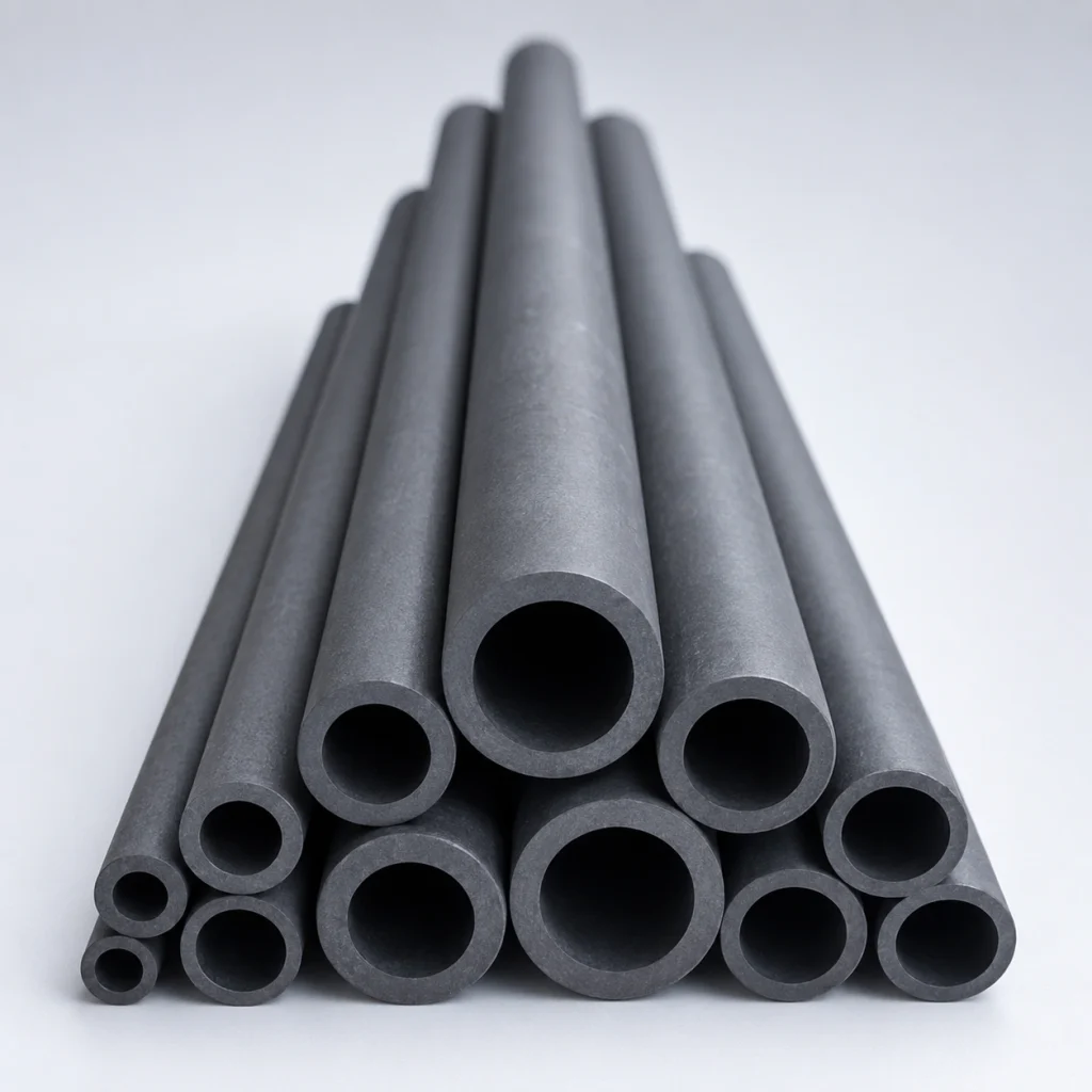
1600°C
High-Temp Stability
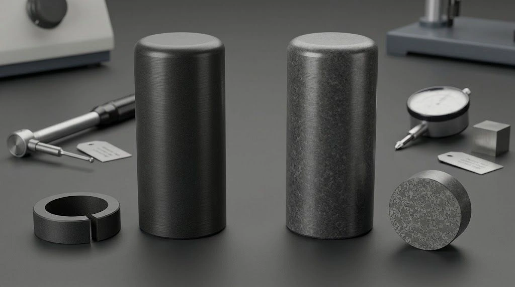
What Is a Silicon Carbide Tube?
SiC tube components take their role from the bore, end structure, material route and installation: a protection tube surrounds a sensor, a kiln roller carries ware, a heat-exchanger tube transfers heat between media, and an electric element generates heat through resistance.
Dense RBSiC/SiSiC and SSiC routes serve different material-selection questions from porous NBSiC and RSiC. The component pages and the material guide below connect each duty to the geometry and specification that matter.
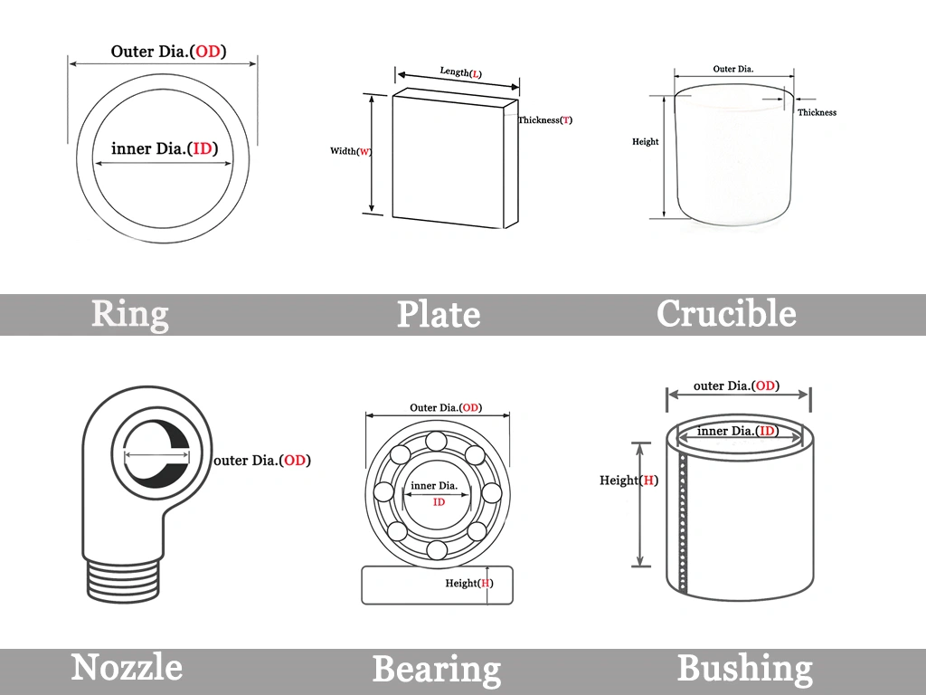
Recognize Four Additional SiC Tube Forms
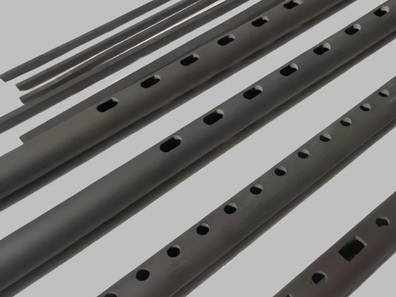
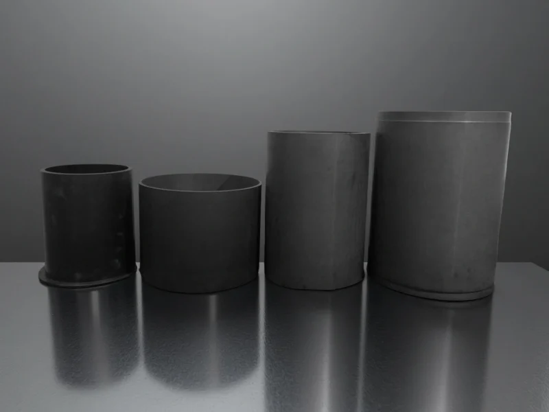

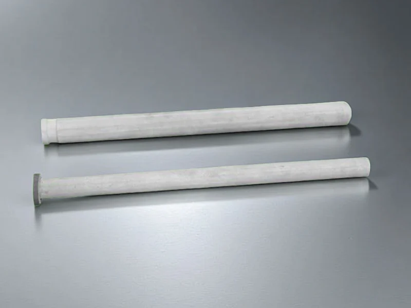
Explore SiC Tube Components
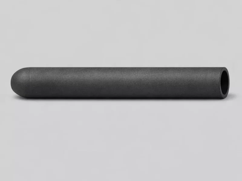
It shields thermocouples and sensors in molten-metal and corrosive atmospheres.
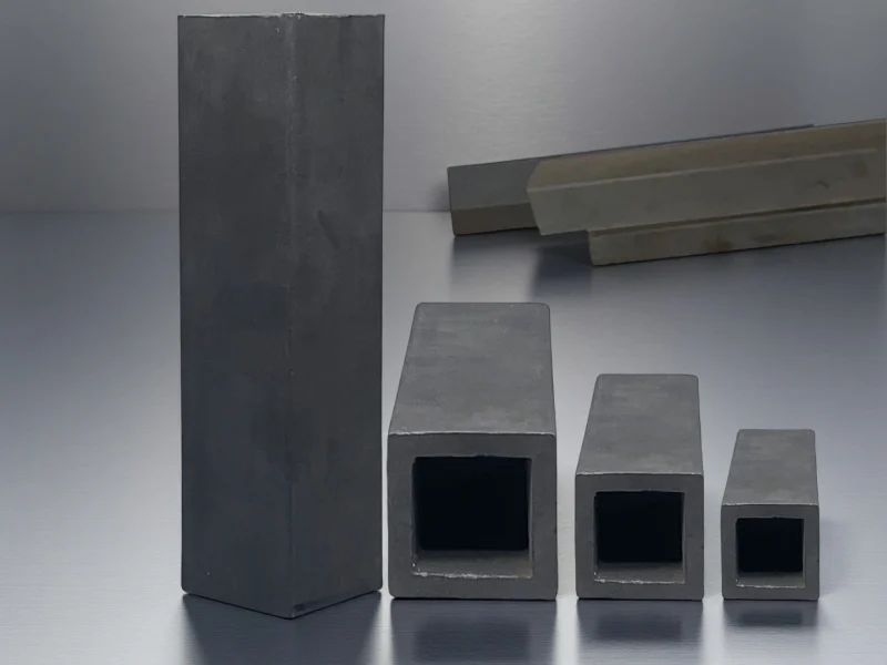
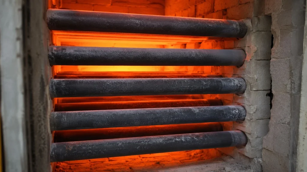
They support kiln cars under continuous high-temperature mechanical loading.
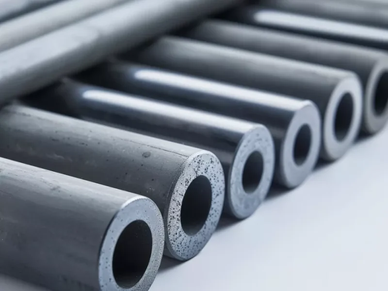
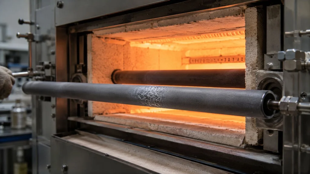
It ensures stable transport of ceramic and powder materials in roller-hearth kilns.
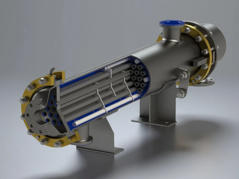
They handle corrosive chemical media and high-heat transfer loads in process industries.
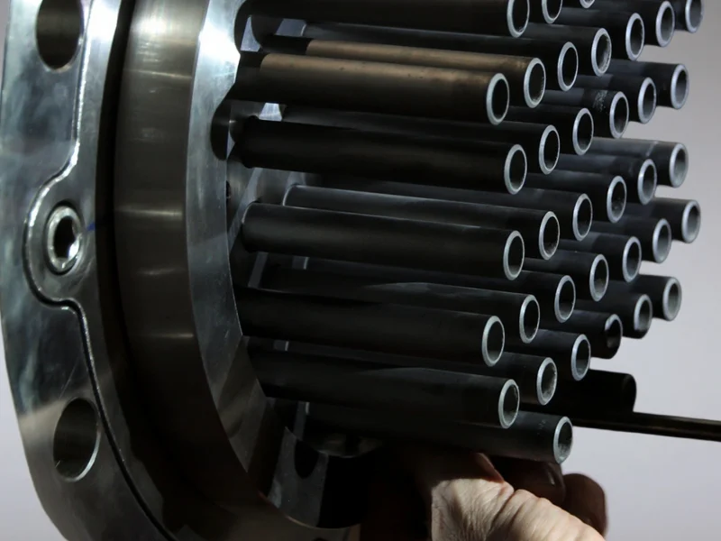
Its structure withstands aggressive chemical, thermal, and particulate conditions.
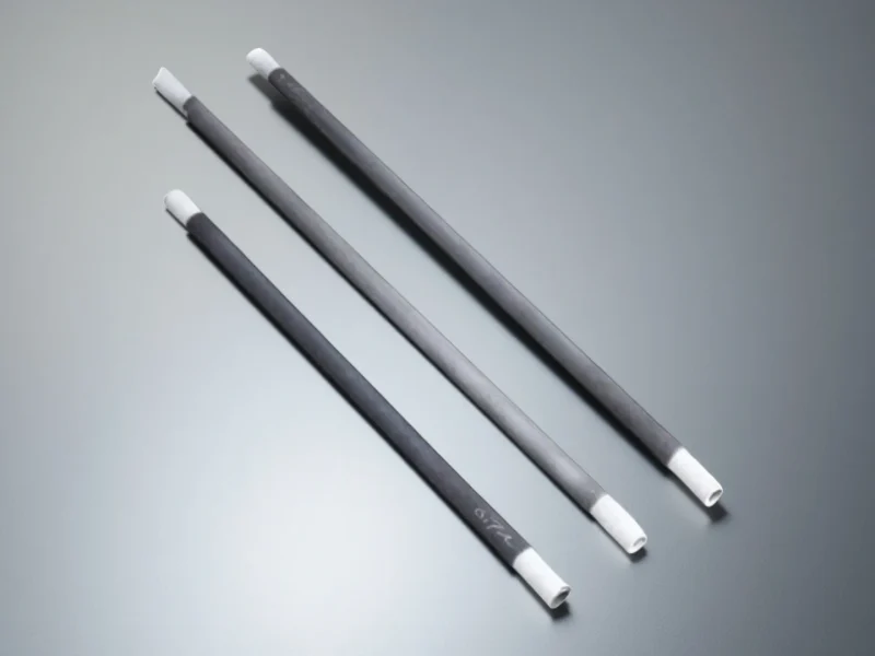
It delivers rapid temperature response for industrial high-heat electric systems.
Choose the Silicon Carbide Tubes by Its Job
The following sizes are available for fast dispatch. Custom sizes are quoted promptly after engineering review of duty, grade and drawing.
| Equipment task | Product route | First selection cue |
|---|---|---|
| Protect a temperature sensor | Protection tubes | Closed/open end, sensor fit and insertion depth |
| Carry ware through a kiln | Kiln rollers | Span, support, rotation and load |
| Exchange heat between process streams | Heat exchanger tubes | Both media, tube ends and tube-sheet interface |
| Generate heat electrically | SiC heating elements | Hot/cold zones, terminals, resistance and circuit |
| Distribute air in a kiln | Cold air pipes | Air path, outlet pattern, manifold and support |
| Line a wear-exposed flow passage | Liner tubes | Ceramic insert, receiving bore, ends and joints |
| Filter a liquid stream | Membrane and porous tubes | Channels, layer/support, feed and seals |
| Lift molten metal | NBSiC riser tubes | Alloy, lift path, tube ends and sealing |
SiC Tube Sizes We Supply
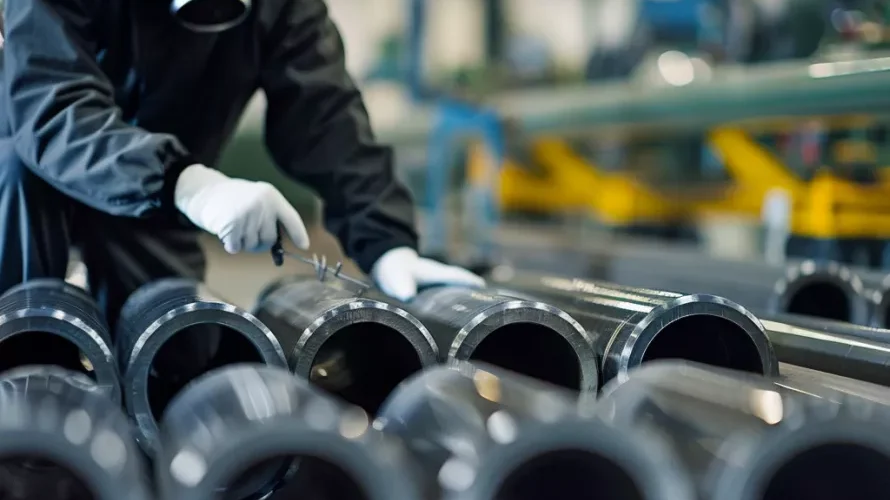
The listed paired sizes cover protection tubes and kiln rollers. The matching product pages provide further configurations and selection details.
| OD × ID × Length (mm) | Grade | Stock Status |
|---|---|---|
| Ø20 × Ø14 × 300 | RBSiC | ✅ In Stock |
| Ø25 × Ø18 × 400 | RBSiC, SSiC | ✅ In Stock |
| Ø30 × Ø22 × 500 | RBSiC | ✅ In Stock |
| Ø40 × Ø30 × 600 | RBSiC, SSiC | ✅ In Stock |
Kiln Rollers
Need a custom size, length, or end configuration?
Custom SiC tubes typically run 3–7 weeks depending on grade and complexity, confirmed per order.
| OD × ID × Length (mm) | Grade | Stock Status |
|---|---|---|
| Ø30 × Ø20 × 2000 | RBSiC | ✅ In Stock |
| Ø40 × Ø30 × 2500 | RBSiC, SiSiC | ✅ In Stock |
| Ø50 × Ø38 × 3000 | RBSiC | ✅ In Stock |
Choose a SiC Tube Material Route
Compare RBSiC/SiSiC, SSiC, NBSiC and RSiC by structure, material properties and service conditions. Use the guide below to match a route to your tube’s function, operating environment and interfaces, then confirm the grade and specification during engineering review.
Reaction-bonded, silicon-infiltrated structure with residual free silicon
Pressureless-sintered, high-purity SiC structure
Nitride-bonded structure for duties based on bond phase and porosity
Recrystallized structure selected around permeability, support and load
These are material-level selection references. Keep each value with its stated temperature and nominal or typical basis, then match the grade, geometry and interfaces to the component.
| Material-level item | RBSiC / SiSiC | SSiC |
|---|---|---|
| Route and structure | Dense reaction-bonded / silicon-infiltrated SiC, with residual free silicon. | Dense pressureless-sintered, high-purity SiC. |
| SiC content | 85 wt% nominal; free silicon 15 wt% nominal. | ≥99 wt%. |
| Bulk density | ≥3.02 g/cm³. | 3.10 g/cm³ typical. |
| Open porosity | ≤0.1 vol%. | <0.1 vol%. |
| Flexural strength | 250 MPa at 20°C; 280 MPa at 1200°C. | 380 MPa; material-level reference. |
| Elastic modulus | 330 GPa at 20°C; 300 GPa at 1200°C. | 420 GPa; material-level reference. |
| Thermal conductivity | 45 W/(m·K) at 1200°C. | 100–120 W/(m·K), ambient material reference. |
| Preliminary temperature ceiling | 1380°C. | 1600°C. |
| Selection focus | Include the residual silicon phase in the medium and atmosphere review. | Confirm component geometry, medium, thermal gradients and manufacturing feasibility. |
Porous Material Routes
| Route | Material-level reference | Component-selection focus |
|---|---|---|
| NBSiC | Nitride-bonded porous SiC; nominal SiC 80 wt% / Si₃N₄ 20 wt%; density 2.80 g/cm³ typical. Porosity 12 vol% typical, with open/total basis and method to be agreed. Thermal conductivity 15 W/(m·K) at 1000°C; preliminary temperature ceiling 1550°C. | Specify the bond phase, porosity basis, oxidation or penetration exposure, and the actual component duty. |
| RSiC | Porous recrystallized SiC route available for component enquiries. | Specify porosity basis, permeability, hot strength, support and loading for the ordered part. |
Match Your SiC Tube to Its Working Conditions
The right tube depends on its function, operating environment and fit within the equipment. Focus on the requirements that matter most to your application.
Electrical Insulation
Define the insulation requirements and how the tube connects to the surrounding assembly.
Sealing & Leakage Control
Confirm the pressure difference, end seals and allowable leakage for the assembled component.
Thermal Cycling & Impact
Review temperature changes, mechanical impact, mounting and support to guide material and geometry selection.
Replacing an Existing Part
Use the current failure mode, installation constraints and target performance to assess a suitable replacement.
Need a custom size, length, or end configuration?
Custom SiC tubes typically run 3–7 weeks depending on grade and complexity, confirmed per order.
Not Sure Which SiC Tube Fits Your Application?
Start with your application or existing part. Our engineers can help compare material routes, review key requirements and narrow down a suitable tube type. Share the information you already have to begin the discussion.
Key Silicon Carbide Tube Applications Across Industrial Systems
SiC tubes serve four main duties — furnace heating, corrosive chemical handling, advanced-materials firing, and molten-metal measurement. Pick your environment below.
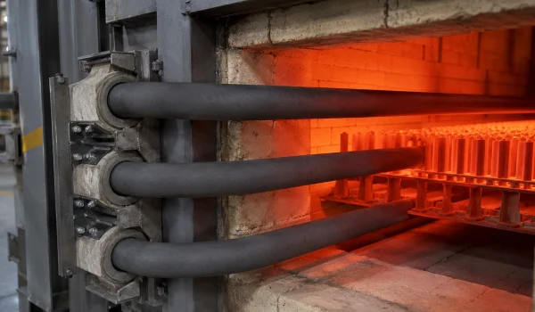
Furnace Thermal Systems
- Survives repeated furnace heating and cooling without creep
- Shields thermocouples and radiant heating from oxidation and molten metal
- High thermal conductivity spreads heat evenly for uniform firing
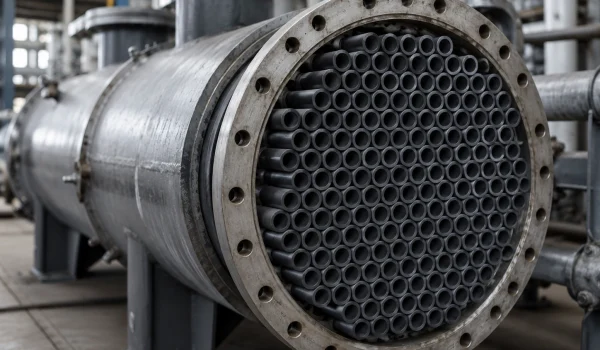
Corrosive Media & Acid Handling
- Resists acids, alkalis and mixed acids that thin metal tubes — reviewed vs your material
- Holds strength in hot corrosive service where metal and graphite fail
- Dense SSiC blocks infiltration and media absorption
Advanced Materials Production
- Holds dimensions better than metal supports through firing and cooling (application-dependent)
- Low thermal expansion keeps shape through rapid cycling
- Stable support under long high-temperature loading
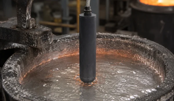
Molten-Metal Measurement
- Protects immersion sensors in molten metal, cutting burnout vs bare or metal-sheathed probes
- Low thermal expansion limits thermal-shock cracking
- Holds strength under turbulent high-temperature flow
Custom SiC Tube Enquiries and Sample Development
ADCERAX supports drawing review, material-route selection, sample planning and inspection criteria for custom and small-batch tube enquiries.
Customization Options
Outside and inside diameter, total and working length, wall transitions and required straightness.
Open or closed ends, flanges, shoulders, holes, slots, sealing areas and assembly interfaces.
Material route, contact media, atmosphere, temperature history and required surface condition.
Function-critical drawing tolerances, inspection points and agreed acceptance criteria.
Customization Process
identify the purchased part and the available project information through the enquiry route below.
resolve critical geometry, material and operating questions and define the component or assembly scope.
agree the drawing revision, inspection method and any representative duty test needed for the application.
Use accepted specifications and inspection records; confirm duty, dimension or material changes before repeat supply.
FAQs About Silicon Carbide Tube
A silicon carbide tube keeps its strength up to about 1,500–1,600°C (route-dependent), while metal alloys often soften or creep above ~1,000°C. Its low thermal expansion reduces thermal-shock cracking and its stable oxide layer resists scaling and contamination. In oxidizing high-temperature service this typically gives longer service life than stainless steel or nickel alloys, with the exact margin depending on temperature, atmosphere, tube geometry and duty cycle.
A Silicon Carbide Tube shields sensors from molten metal, carburizing atmospheres, and high-velocity particulates. The dense microstructure eliminates chemical interaction that would distort readings over long cycles. Stable thermal conductivity supports accurate response times. As a result, calibration drift is significantly reduced across repeated thermal cycles.
A Silicon Carbide Tube offers exceptional chemical inertness in chloride-, bromide-, and acid-rich conditions. The covalent bonding structure prevents ion diffusion and surface degradation. Unlike graphite, the tube does not absorb liquid or develop microcracks. This enables long service periods in acid coolers, corrosive reactors, and flue-gas systems.
A Silicon Carbide Tube features a low CTE (4.0–4.5×10⁻⁶/K) and high thermal conductivity, enabling rapid heat dissipation. This prevents crack propagation when exposed to sudden temperature jumps. Thermal shock cycles exceeding ΔT 250–300 °C are commonly tolerated. This stability is critical for roller kilns, high-speed firing lines, and rapid heating furnaces.
The straightness of a Silicon Carbide Tube depends on forming pressure, uniform sintering, and precise machining. Reaction-bonded microstructures minimize warping during firing. Dimensional inspection typically maintains deviation below 1.0 mm per meter. This consistency is essential for roller systems, heat exchanger bundles, and long process tubes.
Premature failure occurs when porous material grades are used for high-velocity corrosive gases. A dense Silicon Carbide Tube prevents erosion of internal channels. Microstructure uniformity reduces pitting and oxidation layer peeling. Long-term degradation is avoided when gas velocity and chemical concentration are within SiC thresholds.
A Silicon Carbide Tube provides flexural strength in the range of 150–350 MPa, depending on grade and geometry. This strength allows the tube to support furnace loads without creep deformation. High stiffness ensures minimal deflection during long-span support applications. Mechanical reliability contributes to long operational cycles in high-load kilns.
Thermal conductivity of a Silicon Carbide Tube (typically 45–120 W/m·K) depends on purity, porosity, and sintering technique. Dense SSiC and infiltrated SiSiC structures transfer heat efficiently through continuous SiC grain pathways. High conductivity reduces temperature gradients in process chambers. Improved heat uniformity shortens firing or reaction cycles.
Both are high-temperature ceramic tubes, but they serve different applications:
| Decision Factor | Choose SiC Tubes When... | Choose Alumina Tubes When... |
|---|---|---|
| Thermal conductivity | Need rapid heat transfer (45-120 W/m·K) | Heat transfer not critical (20-30 W/m·K) |
| Thermal shock | Severe thermal cycling; rapid heating/cooling | Controlled heating/cooling acceptable |
| Electrical properties | Semi-conductivity acceptable or desired | Electrical insulation required |
| Temperature range | Up to 1600°C (SSiC) | Up to 1730°C (99.7% alumina) |
| Cost | Higher (justified by performance) | Lower |
Bottom line: Use SiC tubes when thermal conductivity, thermal shock resistance, or chemical resistance to acids/alkalis is critical. Use alumina tubes when electrical insulation is needed or for cost-sensitive applications.
What to Send for a Silicon Carbide Tube Quote
To quote a SiC tube, send what you have:
- Tube type: protection / radiant / roller-beam / heat-exchanger tube
- Material route if known: SSiC / RBSiC-SiSiC / RSiC
- OD, ID and length
- Wall thickness
- End design: open both ends / closed one end / flange
- Straightness or tolerance (if critical)
- Operating temperature and atmosphere
- Media or corrosion (acids, alkalis, molten metal, gases)
- Load and span (roller and beam tubes)
- Drawing, sketch or photo of the old part
- Old-part material and failure mode (for replacement)
- Quantity and target lead time
Send what you have — even a drawing or an old-part photo is enough to start. Our engineers confirm route, material and feasibility before quoting.
*Our team will answer your inquiries within 24 hours.
*Your information will be kept strictly confidential.
info@adcerax.com
Tel:+86-0731-84428843
WhatsApp:+86 19311583352
Within 24 hours