Silicon carbide heat-exchanger tubes belong in selected municipal waste incineration (WtE) heat-recovery zones when the duty needs both high thermal conductivity and resistance to hot corrosive flue gas plus alkali chloride and sulfate deposits. They are not a universal metal boiler-tube drop-in. The decision turns on zone location, flue and ash chemistry, seal and differential-expansion design, cleaning method, and thermal-shock exposure.
3-Minute Decision: SiC in This Incineration Heat-Recovery Zone?
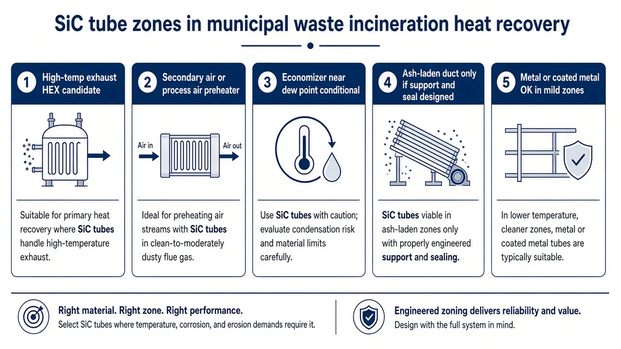
- Hot corrosive exhaust HEX needing conductivity plus chloride and sulfate resistance. SiC is a fair candidate when ash chemistry and seal design are reviewed with the tube route.
- Secondary air or process air preheater with a metal corrosion history. SiC is a candidate if expansion clearance and tubesheet seals are designed for ceramic, not copied from steel practice.
- Cold-end economizer near acid dew point. Conditional. Verify condensate and wash chemistry first; do not default to SiC because the gas is "corrosive."
- Unknown waste mix and no ash chemistry. Do not RFQ "SiC incinerator tube" alone. Zone, flue chemistry, and deposit data must travel with the inquiry.
- Replacing metal boiler tubes. Redesign supports, tubesheet or seal, and cleaning. Treat it as an exchanger change, not a spare-parts swap.
Risks That End RFQs
Most failed incineration SiC inquiries stall for the same reasons: missing zone definition, no ash or flue chemistry, and no seal or cleaning plan. Address these before quoting wall thickness or route name.
- HCl, SO2, SO3, and alkali chloride-sulfate deposits. Municipal waste flue gas commonly carries acid gases with water vapor and oxygen. Deposited alkali chlorides and sulfates, often with Pb or Zn salts, can attack metal walls and foul ceramic surfaces.
- Fly-ash erosion. Heterogeneous MSW streams raise dust loading. High local velocity roughens walls and can initiate cracks at edges or supports. State velocity and dust loading on the RFQ.
- Fouling that cuts duty and raises skin temperature. Low-conductivity ash layers insulate the tube from the hot gas, cut recovered heat, raise outer skin temperature, and may shift the deposit regime. Fouling is often the first performance problem, not wall thinning.
- Soot-blow, lance, or wash thermal shock. Cleaning protects duty but can impose sudden temperature differentials. Capture cleaning medium, frequency, and proximity to the tube bundle.
- Seal and differential-expansion failure. Ceramic tubes expand differently from steel tubesheets and frames. Leakage often starts at ends, gaskets, or mechanical fittings rather than in the tube body.
Metal tubes remain appropriate in mild, lower-risk zones with known chemistry and established code practice. SiC enters the review when chloride and sulfate deposits, hot oxidizing flue gas, and heat-transfer duty make alloy or coating maintenance unreliable for that zone.
Geometry and Role Boundaries
Assign fit by heat-recovery role first. The same SiC family behaves differently as a high-temperature exhaust HEX tube, secondary air preheater tube, cold-end economizer tube, or ash-laden duct exchanger tube. Fit, advantage, main risk, and what to verify differ by position.
| Role | Fit (qualitative) | Advantage | Main risk | Verify |
|---|---|---|---|---|
| High-temp exhaust HEX | Strong candidate | Conductivity + corrosion resistance | Ash deposit and cleaning shock | Gas T envelope + ash chem |
| Secondary air / process air preheater | Strong candidate with design review | Reduces metal corrosion exposure | Seal and expansion mismatch | Tubesheet / gasket for ceramic |
| Economizer cold-end | Conditional | Corrosion-resistant wall if dry | Acid condensate and wash attack | Dew point + wash chemistry |
| Ash-laden duct HEX | Candidate if supported | Erosion + corrosion resistance | Particle impact and plugging | Velocity, pitch, cleaning access |
| Metal boiler-tube swap | Not drop-in | Intrinsic bulk corrosion resistance | Brittle ends; code and support redesign | Full mechanical redesign package |
For guidance on tube layout, pitch, and material selection, see silicon carbide heat exchanger tube design and selection.
Why SiC vs Metal, Alloy, or Coated Tubes
- Carbon steel and many stainless alloys. Familiar and code-ready in mild zones. In chloride- and sulfate-rich WtE deposits they can waste quickly. SiC avoids the electrochemical corrosion path that drives metal wastage in those deposits.
- Higher alloys. Toughness and pressure-boundary familiarity help in controlled zones, but sticky alkali deposits can still defeat the surface. Cost rises without removing seal and cleaning design work.
- Coated metal. Thermal-spray or other coatings can protect a metal pressure boundary, yet pinholes, edge gaps, and cycling delamination reopen the substrate. SiC corrosion resistance is bulk material behavior, not a coating film.
- Dense SSiC. High SiC content with no intentional free-silicon infiltrate. Useful when residual silicon chemistry is unwanted and the duty needs dense, low-open-porosity HEX walls. TDS material selection ceiling is commonly cited near 1600 °C as an initial selection ceiling, not a continuous loaded service rating or process certification for a named incinerator recipe.
- RBSC / SiSiC. Reaction-bonded / siliconized route with a residual free-silicon phase (TDS nominal free Si about 15 wt%). Density and conductivity help structural HEX tubes when flue chemistry and deposit salts stay inside free-Si compatibility. That residual silicon phase constrains chemical fit; it is a route property, not a blanket pass and not an absolute ban for every WtE zone. Name acid-gas, alkali, and molten-salt ash chemistry on the RFQ before locking this route. When free-Si chemistry is unacceptable for the deposit set, review dense SSiC instead. TDS material selection ceiling for this route is commonly cited near 1380 °C, again a selection ceiling, not continuous loaded service. Atmosphere, load, dwell, and cycling must be defined on the RFQ.
- Porous NBSiC / recrystallized routes. Generally not first choice for gas-tight flue HEX tube walls. Keep them out of pressure-tight gas boundaries unless a specific non-tight duty is proven.
Temperature ceilings above are initial material selection figures from the dense/bonded SiC TDS family. They do not replace zone chemistry review or finished-part leak specification. For route-by-route property tables, see the SSiC vs RBSC vs SiSiC tube grade selection guide.
Do Not Misdiagnose Heat-Recovery Loss as "SiC Tube Corrosion" Alone
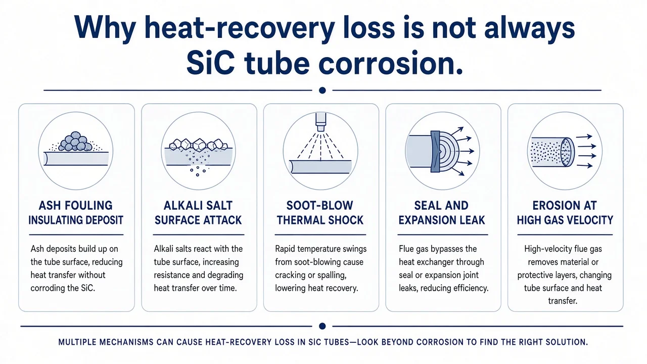
Reduced heat duty, rising pressure drop, leakage, or cracked tubes after a SiC install are often system problems, not proof that "SiC corroded."
- Ash fouling and deposit insulation. Duty loss often tracks deposit thickness and composition before wall thinning. Sample deposits and inspect outer surfaces before another material swap.
- Alkali salt surface attack misread as bulk failure. Sticky chloride and sulfate layers can roughen or locally attack surfaces while the tube body remains structurally intact. Chemistry review of the deposit matters more than a generic "SiC failed" label.
- Soot-blow or wash thermal shock. Ring cracks or one-sided longitudinal cracks often point to cleaning or cold-air inleakage, not uniform chemical wastage.
- Seal and expansion leak. Gas or fluid leakage commonly starts at tubesheet fittings, gaskets, or ceramic cements. Inspect ends before blaming the tube bore.
- Wrong zone or unqualified free-Si chemistry. A route acceptable in a hot dry exhaust HEX may be a poor match near acid dew point or under aggressive alkali deposits. Role assignment errors look like material failures.
Semiconductor vertical-diffusion SiC furnaceware requires a different purity and requalification approach from incineration heat exchangers. For that application, see SiC tubes in semiconductor vertical diffusion furnaces.
RFQ Checklist for SiC Tubes in Waste Incineration Heat Recovery
Send a zone-complete RFQ. "SiC tube for incinerator" alone is not enough for engineering review.
After zone and ash chemistry clear the route, confirm OD/ID/wall/length and end finish on the silicon carbide tube product page so the RFQ drawing matches a real tube form—not a metal boiler drop-in assumption.
- Heat-recovery zone and exposure description (exhaust HEX / air preheater / economizer / ash-laden duct)
- Flue-gas temperature: inlet, outlet, peak, and start-stop conditions, with an initial operating range if detailed measurements are not yet available
- Gas chemistry as available: HCl, SO2, SO3, O2, H2O, including measured concentrations where available
- Ash chemistry: Na, K, Cl, S, Pb, Zn plus particle size when known
- Gas velocity and dust loading
- Heat duty target and allowable pressure drop
- Drawing: OD / ID / wall / length / ends / straightness (use drawing and catalog review)
- Support, tubesheet, and seal concept designed for ceramic differential expansion
- Cleaning method: soot-blow, lance, or wash parameters
- Validation plan: ash exposure review, thermal cycling, leak test, deposit inspection
Leak-tight assemblies need a finished-part leak specification. Corrosion resistance and service life require validation for the actual operating conditions. When waste feed chemistry swings seasonally, a monitored pilot section with ash sampling and duty tracking is often safer than a full-plant swap on incomplete data.
Cement kiln preheaters involve different material and operating requirements from municipal waste incineration heat exchangers. For alumina applications in that setting, see alumina protection tubes in cement kiln preheaters.
Frequently Asked Questions
Why are SiC tubes considered for municipal waste incineration heat recovery?
Because selected WtE zones combine hot corrosive flue gas, alkali chloride and sulfate deposits, fly-ash erosion, and a real heat-transfer duty. Dense SiC routes offer bulk corrosion resistance with useful thermal conductivity. Success still depends on zone, seal, and cleaning design, not the tube grade name alone.
Can SiC tubes replace metal boiler tubes directly?
Usually no. SiC is brittle and needs ceramic-appropriate supports, expansion clearance, and end seals. Treat the change as a purpose-designed ceramic exchanger assembly, not a welded steel spare-parts swap.
Is RBSC / SiSiC acceptable in incineration flue gas?
Only after free-Si chemistry review against the actual flue and deposit set. The residual free-silicon phase (about 15 wt% nominal on the TDS) constrains chemical and temperature fit. Put acid-gas, alkali, and molten-salt ash chemistry on the RFQ. If that phase is unwanted, review dense SSiC. Do not assume a blanket ban or a blanket pass for every WtE zone.
What usually limits performance before the tube wall "fails"?
Ash fouling that cuts duty, alkali salt deposits that change surface attack, soot-blow thermal shock, high-velocity erosion, and seal leakage from differential expansion. The tube body is often not the first failure point.
What should an RFQ include?
Zone, temperature envelope, gas and ash chemistry as available, velocity and dust loading, duty and allowable pressure drop, tube drawing, seal and support concept, cleaning method, and a validation plan. Without those fields, a supplier cannot confirm route, sealing approach, or thermal-shock risk.