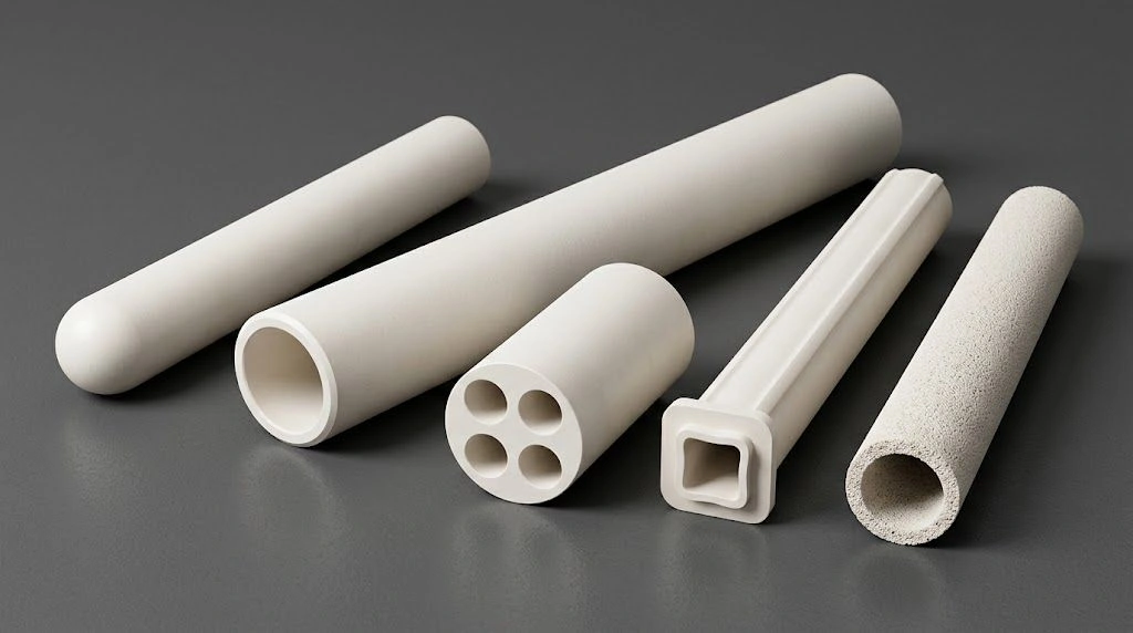
Alumina combustion / setter boats in industrial sintering and kiln-furniture systems often become the hidden limiter of line stability—especially when warpage, uneven burnoff, or unexpected scrap shows up on continuous firing and debinding lines.
In industrial sintering lines, alumina combustion/setter boats act as kiln furniture under load, peak temperature, and thermal cycling—unlike lab thermal-analysis boats used for calcination or materials studies. It addresses heat transfer, load deformation, combustion exposure, thermal shock, creep life, and replacement criteria so engineers can specify purity, density, geometry, and RFQ fields with clear duty boundaries.
Accordingly, the discussion moves from functional positioning to line-level process control, so each decision about the combustion boat supports yield, reliability, and predictable kiln performance. For product geometry and custom duty matching, see the alumina boat catalog and custom services RFQ path.
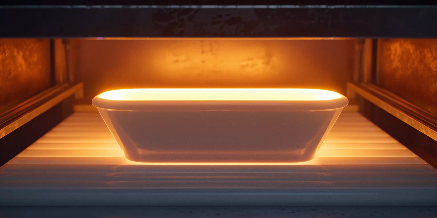
Before material grades or kiln settings are compared, the functional position of the alumina combustion boat must be established. Moreover, its structural and thermal behavior creates boundary conditions that production teams experience as stability or drift.
Functional Position of Alumina Combustion Boats in Kiln Furniture Systems
Alumina combustion boats in industrial kilns serve as both carriers and process interfaces, not merely as containers. Moreover, they couple mechanical load, heat transfer, and atmosphere exposure into a single physical platform that directly influences firing consistency. Therefore, production engineers should treat the boat as a controlled element within the kiln furniture system rather than an interchangeable accessory.
Load Bearing and Structural Interface in Continuous Firing Lines
In continuous firing lines, the alumina combustion boat becomes the first mechanical layer between green bodies and the kiln structure. In high-throughput operations, a single boat may carry a substantial mass of parts or powder compacts depending on geometry and stacking pattern—state the load map on RFQ.
On a continuous line (illustrative takt and duty—confirm on RFQ), even minor boat deflection can propagate into part distortion. Monitor midspan sag and flatness drift against your drawing limit; when contact pressure becomes uneven, shrinkage scatter rises—especially for thin or long components.
Therefore, the alumina combustion boat functions as a structural datum, and its stiffness under load is directly linked to dimensional repeatability.
Thermal Mediation Between Product and Furnace Atmosphere
Industrial kilns impose aggressive thermal flux, and the combustion boat shapes how that flux is delivered to the product. In high-temperature sintering zones (grade-dependent selection ceilings—e.g. AD-ALU-995 ≈1650 °C, 997 ≈1700 °C, 999 ≈1750 °C long-term; not a continuous loaded-life guarantee), radiative heating typically dominates, yet conduction through kiln furniture contacts still establishes local temperature gradients.
In practice, densely loaded boats can still show through-boat temperature gradients even when kiln thermocouples remain stable. Steep ramps and large through-boat ΔT raise thermal-shock and uniformity risk—the boat absorbs and re-radiates heat and may shield parts depending on wall height and profile. Specify ramp, soak, and support on RFQ. Moreover, during debinding1 or binder burnout2, gas exchange near the part surface is influenced by how the boat channels airflow.
Accordingly, boat geometry and thermal mass mediate both temperature uniformity and atmosphere access, shaping burnoff completeness and sintering homogeneity.
Why Combustion Boat Design Shapes Sintering Consistency
Sintering consistency depends on repeatable thermal history and uniform constraint. Although kiln recipes are usually standardized, the combustion boat quietly introduces variance when its shape, mass, or surface condition changes over time.
As boats age in service, subtle surface roughness and localized glazing can accumulate. Operators may first notice increased sticking or inconsistent powder release; warped or cracked boats raise scrap risk when parts experience uneven seating or local atmosphere stagnation. These issues rarely appear suddenly—they develop progressively as the boat ages and deforms. Set replacement criteria (flatness, cracks, contamination) on RFQ rather than assuming a universal cycle count.
Thus, combustion boat design and lifecycle control are direct levers for yield stability, especially when product tolerances tighten and debinding windows narrow.
Summary of Functional Contributions in Kiln Furniture Systems
| Functional Domain | Typical Range | Production Consequence |
|---|---|---|
| Payload per boat | Duty- / geometry-dependent (confirm on RFQ) | Influences sag and part distortion |
| Line takt / cycle profile | Process-typical; confirm on RFQ | Sets thermal and handling stress frequency |
| Sintering zone temperature | Grade screening vs TDS ceiling (995≈1650 / 997≈1700 / 999≈1750 °C) | Drives radiative dominance and creep risk |
| Cross-boat temperature gradient | Line-dependent (specify ramp/soak/support on RFQ) | Alters shrinkage uniformity |
| Surface / flatness drift with reuse | Line- / duty-dependent | Raises sticking and scrap risk |
Before thermal behavior and deformation mechanisms are evaluated, the intrinsic material properties of alumina combustion boats must be clarified. Moreover, long-cycle industrial sintering exposes material limits that short laboratory trials rarely reveal.
Material Properties of Alumina Combustion Boats at Industrial Temperatures
Alumina combustion boats are selected for industrial sintering primarily because their material properties remain stable under sustained high-temperature exposure. Moreover, purity level, microstructural density, and thermal expansion behavior collectively define whether boats maintain geometry and load-bearing capability across thousands of firing hours.
Alumina Purity and Phase Stability in Long Cycle Sintering
Alumina purity governs phase stability during prolonged industrial sintering. High-purity alumina ≥99.5 wt% Al₂O₃ (AD-ALU-995-class screening; confirm COA/TDS) remains in the α-alumina phase under continuous high-temperature duty within the selected grade’s TDS ceiling—use grade-dependent ceilings (995≈1650 °C; 997-class ≈1700 °C; 999≈1750 °C), not a universal 99.5→1700 °C rating.
In contrast, alumina bodies containing higher glassy-phase content begin to soften at lower temperatures during long dwell cycles (process-typical dwell—confirm on RFQ). Production engineers often observe gradual warpage rather than sudden failure, which accumulates unnoticed until part alignment issues appear. This slow deformation directly affects stacking precision and heat exposure consistency.
Therefore, high-purity alumina combustion boats provide phase-stable geometry, supporting predictable sintering behavior over extended production campaigns.
Microstructure Density and Creep Resistance Under Load
Microstructural density directly influences creep resistance at elevated temperatures. Dense alumina combustion boats typically exhibit bulk densities above 3.85 g·cm⁻³, which limits grain boundary sliding under sustained load.
In industrial settings where boats support sustained static loads at high temperature, creep rises with temperature, stress, and span—request creep/deformation allowance on RFQ (align with TDS footnotes; do not treat published strain rates as SLA). Operators frequently notice that low-density boats show earlier midspan deflection, while dense bodies maintain flatness longer under the same duty.
Accordingly, high-density microstructures enhance creep resistance, preserving load distribution and dimensional stability in setter boat systems.
Thermal Expansion Compatibility with Kiln Furniture Assemblies
Thermal expansion compatibility determines how alumina combustion boats interact with adjacent kiln furniture components. Typical dense alumina CTE is about 7–8 × 10⁻⁶ K⁻¹; ADCERAX TDS mean is about ~7.6 × 10⁻⁶ K⁻¹ (25–800 °C)—confirm grade and measurement interval rather than pinning a single 8.0 value to 1000 °C.
When boats are paired with supports made from mullite, cordierite, or composite kiln plates, mismatched expansion can introduce contact stress during heating and cooling. In continuous kilns, this mismatch may generate edge chipping or localized stress marks over repeated cycles. Engineers who align expansion characteristics across the furniture stack report reduced cracking incidence and smoother thermal transitions.
Thus, thermal expansion matching across kiln furniture assemblies minimizes stress concentration, extending overall system service life.
Summary of Alumina Material Property Impacts in Industrial Sintering
| Material Parameter | Typical Value | Operational Impact |
|---|---|---|
| Alumina purity (wt%) | ≥99.5 screening (confirm COA/TDS; grade-dependent ceiling) | Phase stability within selected grade ceiling |
| Bulk density (g·cm⁻³) | ≥3.85 typical dense screening | Improved creep resistance |
| Creep / deformation | Rises with T, stress, span — request allowance on RFQ | Long-term flatness retention |
| Thermal expansion (K⁻¹) | ~7–8 typical; TDS mean ~7.6×10⁻⁶ (25–800 °C) | Stress compatibility |
| Deformation / replacement trigger | Line-dependent (flatness, cracks, contamination) | Predictable lifecycle control |
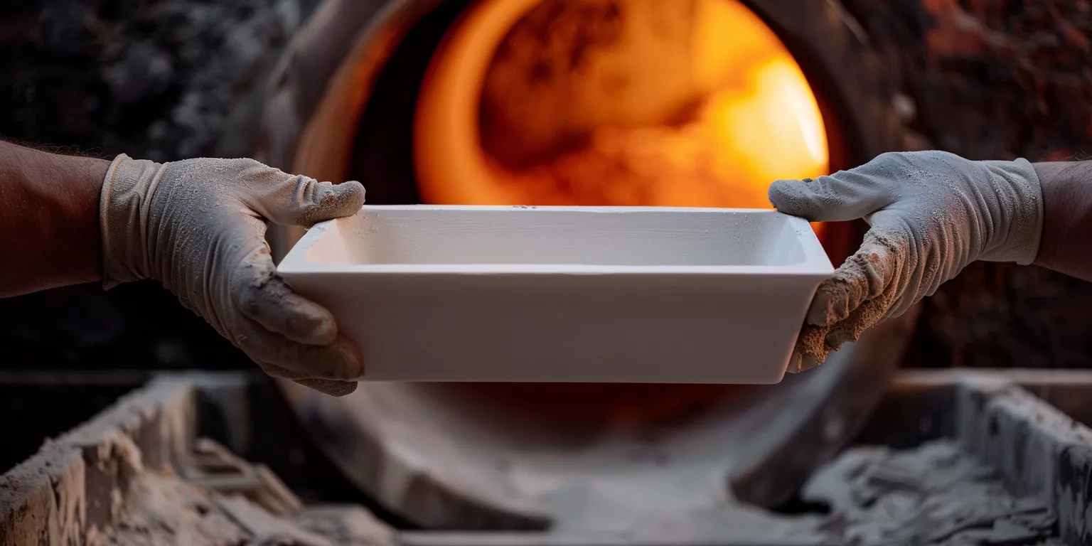
Before mechanical deformation and service life are addressed, heat transfer behavior must be examined under real industrial kiln conditions. Moreover, alumina combustion boats actively shape how thermal energy reaches products across firing zones.
Heat Transfer Behavior in Industrial Kilns
In industrial kilns, heat transfer is governed by radiation, conduction, and limited convection. Therefore, alumina combustion boats influence temperature uniformity, thermal lag, and local hot spots that directly affect sintering outcomes.
Radiative Dominance in High Temperature Sintering Zones
At sintering temperatures above 1400 °C, radiative heat transfer becomes the dominant mechanism. Alumina combustion boats absorb and re-emit radiant energy, acting as secondary radiators within the kiln chamber.
In practice, boats with thicker walls or higher thermal mass introduce heating lag before parts reach equilibrium. This lag becomes critical in short-cycle processes, where insufficient soak time leads to under-sintered zones. Conversely, well-balanced boat profiles help smooth radiant fluctuations—radiation often dominates at high T; confirm geometry effects on RFQ rather than assuming a fixed ΔT reduction.
Accordingly, radiative interaction between kiln walls and combustion boats controls thermal uniformity, especially in high-temperature zones.
Conductive Paths Through Kiln Furniture Stacks
Conduction occurs where alumina combustion boats contact setters, plates, or rollers. These contact points create thermal bridges that can either stabilize or distort temperature distribution.
In stacked kiln furniture systems, conduction through contact interfaces remains a secondary but important path. If contact area is uneven, localized overheating or cooling appears near edges or corners. Operators often notice discoloration or differential shrinkage in products placed above these regions.
Thus, controlled contact geometry and flatness are essential to maintain consistent conductive heat paths through the kiln furniture stack.
Impact of Boat Geometry on Temperature Uniformity
Boat geometry determines how heat is distributed across the load surface. Shallow, open profiles promote even exposure, while deep walls can shield products from direct radiation.
Deep-wall boats can show larger internal temperature gradients across the load width than shallow open profiles. Over repeated cycles, these gradients translate into variable densification and inconsistent mechanical properties. Wall height is geometry-example / drawing-dependent—small profile changes can meaningfully change gradients; specify on RFQ.
Therefore, geometry optimization of alumina combustion boats directly improves temperature uniformity, supporting stable sintering results across production batches.
Summary of Heat Transfer Characteristics in Industrial Kilns
| Heat Transfer Aspect | Typical Contribution | Process Effect |
|---|---|---|
| Radiative heating at high T | Typically dominant above ~1400 °C | Controls peak temperature exposure |
| Conductive contribution | Secondary; contact-geometry dependent | Can create local gradients |
| Heating lag / soak | Mass- and profile-dependent | Affects soak effectiveness |
| Internal load-width gradient | Line- / geometry-dependent | Drives densification variance |
| Wall height / profile | Drawing-dependent example | Improves uniformity when matched to duty |
Before chemical exposure and thermal shock are discussed, mechanical load behavior must be evaluated. Moreover, deformation of alumina combustion boats under industrial load conditions often defines the true service limit in sintering lines.
Mechanical Load Distribution and Deformation Risk
In industrial kiln furniture systems, alumina combustion boats experience sustained mechanical loading at elevated temperatures. Therefore, load distribution, creep behavior, and stress concentration directly influence dimensional stability and product quality over repeated firing cycles.
Static Load from Green Bodies and Stacked Products
During loading, alumina combustion boats support the combined mass of green bodies, setters, and occasionally stacked components. Static load is duty- and geometry-dependent (confirm mass map on RFQ), with localized contact pressures forming beneath dense part clusters.
In practice, uneven loading leads to asymmetric stress distribution across the boat span. Off-center loads amplify midspan deflection versus centered loads—monitor against your drawing limit rather than treating a percentage deflection increase as SLA. This deflection alters part seating angles, which then propagates into non-uniform shrinkage during sintering.
Consequently, uniform load placement is essential to minimize bending stress and preserve dimensional repeatability.
High Temperature Creep and Long Term Shape Retention
At sintering temperatures above 1450 °C, alumina combustion boats are subject to time-dependent creep. Although α-alumina maintains structural integrity, grain boundary sliding occurs under sustained stress.
Creep rises with temperature, stress, and span under sustained production loads—request creep/deformation allowance and flatness limits on RFQ. Over repeated firing cycles, strain can manifest as permanent midspan sag (monitor against drawing limit; geometry example only). Such deformation rarely causes immediate failure but gradually disrupts stacking geometry.
Therefore, creep resistance governs long-term shape retention, making it a critical design consideration for industrial combustion boats.
Stress Concentration at Edges Corners and Contact Points
Stress concentration arises at geometric discontinuities, including sharp corners, thin wall transitions, and point contacts with underlying kiln furniture. These regions experience amplified tensile stress during heating and cooling.
Edge cracking or chipping often initiates where contact points coincide with thermal gradients. Rounded edges and reinforced contact zones help reduce peak stress intensity and can delay crack initiation—treat as qualitative geometry guidance, not a guaranteed life extension percentage.
Thus, geometry refinement at stress concentration zones mitigates deformation risk, enhancing mechanical reliability under cyclic loading.
Summary of Mechanical Load and Deformation Factors
| Mechanical Factor | Typical Range | Operational Impact |
|---|---|---|
| Static load per boat | Duty- / geometry-dependent (RFQ mass map) | Bending stress magnitude |
| Load centering | Keep load centered vs drawing | Limits deflection amplification |
| Creep / sag | Rises with T, stress, span — RFQ allowance | Long-term sagging risk |
| Permanent deflection | Monitor midspan sag vs drawing limit | Stacking misalignment |
| Edge / fillet geometry | Rounded / reinforced contacts preferred | Reduces peak stress (qualitative) |
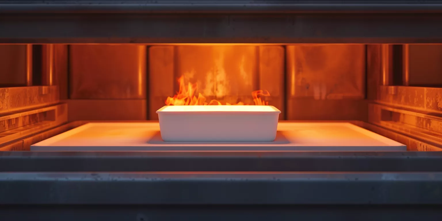
Before lifecycle management and replacement planning are addressed, resistance to rapid temperature change must be evaluated. Moreover, thermal shock failure often emerges unexpectedly in high-throughput industrial sintering lines.
Thermal Shock Resistance and Rapid Cycling Conditions
Alumina combustion boats in industrial kilns are repeatedly exposed to rapid heating and cooling during loading, firing, and unloading. Therefore, thermal shock resistance becomes a decisive factor for maintaining structural integrity under accelerated production schedules.
Heating Rate Effects During Kiln Ramp Up
Industrial sintering lines often use relatively aggressive heating rates during ramp-up to maximize throughput. Under these conditions, temperature gradients develop across the thickness of the alumina combustion boat—specify ramp, soak, and support on RFQ.
Steep ramps and large through-boat ΔT raise thermal-shock risk and induce tensile stress at the surface, especially near corners and contact points. Boats with insufficient wall-thickness uniformity tend to develop microcracks earlier under aggressive cycling, even when bulk strength remains unchanged.
Accordingly, controlled heating profiles and uniform wall design reduce thermal shock accumulation, stabilizing performance under aggressive ramp conditions.
Cooling Stress During Unloading and Transfer
Cooling introduces equally severe thermal gradients, particularly when boats exit hot zones into ambient environments. In tunnel kilns, abrupt unloading can create steep surface cooling rates—manage staged cooling or shielding where the duty requires it.
Abrupt exposure to ambient air can generate high thermal stress relative to alumina’s elevated-temperature flexural capacity. Cracking often initiates at thin sections or near support contacts. Staged cooling or shielding can reduce crack-related scrap risk—warped or cracked boats raise scrap risk; do not treat percentage scrap cuts as contractual SLA.
Thus, cooling management is as critical as heating control in preserving combustion boat integrity.
Repeated Thermal Cycling and Microcrack Accumulation
Thermal shock damage accumulates gradually through microcrack initiation and propagation. Each cycle may introduce microscopic flaws that remain invisible until they coalesce.
Under repeated thermal cycling, alumina combustion boats can lose stiffness even without visible cracking. This loss manifests as increased deflection under load and subtle dimensional drift. Once microcrack density reaches a threshold, failure probability rises sharply—set inspection and replacement criteria on RFQ.
Therefore, cycle count monitoring and proactive inspection are essential to manage thermal shock-related degradation.
Summary of Thermal Shock Influences in Industrial Sintering
| Thermal Shock Factor | Typical Value | Operational Consequence |
|---|---|---|
| Heating ramp | Specify ramp on RFQ | Surface-core gradient risk |
| Cooling / unload | Avoid abrupt ambient quench | Tensile stress generation |
| Through-boat ΔT | Line-dependent; steep ΔT raises shock risk | Crack initiation risk |
| Staged cooling / shielding | Qualitative risk reduction | Improved service life |
| Stiffness after cycling | Duty-dependent drift | Increased deformation |
Before line-level optimization and RFQ field definition are discussed, chemical exposure during combustion and debinding must be evaluated. Moreover, alumina combustion boats often operate in chemically aggressive atmospheres that accelerate surface degradation.
Chemical Stability During Combustion and Debinding
Alumina combustion boats encounter reactive gases, volatilized binders, and transient condensates during debinding and burnout. Therefore, chemical stability under mixed atmospheres directly affects surface integrity, sticking behavior, and long-term reusability within industrial sintering systems.
Interaction with Binder Decomposition Products
During debinding, organic binders decompose into hydrocarbons, CO, CO₂, and trace acidic species. These gases interact with hot alumina surfaces, particularly within 300–600 °C where partial oxidation is incomplete.
Boats exposed to high binder loading can develop surface glazing or carbonaceous deposits over repeated cycles. These deposits reduce surface wettability and increase adhesion risk during subsequent high-temperature steps. Dense alumina with low open porosity limits adsorption depth and helps reduce deposit buildup—confirm atmosphere and chemistry on RFQ.
Accordingly, low-porosity alumina surfaces improve chemical resilience during repeated debinding cycles.
Resistance to Alkali and Fluxing Contaminants
In some ceramic formulations, alkali-bearing additives or residual salts volatilize and condense on kiln furniture. At temperatures above 1200 °C, these species can react with alumina to form low-melting phases.
Localized alkali attack can initiate surface pitting over repeated cycles, especially near exhaust paths. Once fluxing occurs, surface softening promotes sticking and accelerates wear. Higher-purity alumina and smoother surface finishes help reduce flux-related damage—confirm atmosphere, load map, and chemistry on RFQ rather than assuming a percentage damage cut.
Thus, chemical resistance to alkali species is essential for maintaining surface integrity in combustion boats.
Atmosphere Variability and Oxidation Potential
Industrial kilns often transition between oxidizing, neutral, and mildly reducing atmospheres. Alumina itself remains chemically stable; however, atmosphere variability influences surface reactions with contaminants.
In mixed-atmosphere kilns, operators note that fluctuating oxygen potential can alter deposit chemistry, making residues harder to remove mechanically. Boats used in stable oxidizing environments typically retain more consistent surface condition, whereas variable atmospheres shorten effective service intervals—cycle life is line-/duty-/geometry-dependent.
Therefore, process atmosphere consistency supports predictable chemical stability, extending alumina combustion boat usability.
Summary of Chemical Stability Considerations
| Chemical Exposure Factor | Typical Range | Operational Impact |
|---|---|---|
| Debinding temperature band | Process-typical organic burnout window | Deposit formation risk |
| Low open porosity | Limits adsorption depth (qualitative) | Improved cleanliness |
| Alkali / flux attack | Duty- / atmosphere-dependent | Surface pitting risk |
| Purity / finish upgrade | Screening aid; confirm on RFQ | Extended surface life |
| Atmosphere consistency | Stable oxidizing often kinder to surface | More predictable reuse |
Before procurement decisions and line optimization are finalized, service life behavior must be evaluated at the system level. Moreover, lifecycle management of alumina combustion boats determines both process stability and maintenance predictability.
Service Life Management and Replacement Strategy
Alumina combustion boats in industrial sintering systems rarely fail abruptly; instead, their performance degrades progressively. Therefore, managing service life through monitoring, rotation, and planned replacement is essential for maintaining consistent kiln output and avoiding unplanned downtime.
Progressive Deformation and Flatness Drift
Over repeated high-temperature cycles, alumina combustion boats experience gradual deformation driven by creep, microcracking, and surface wear. In continuous production lines, measurable flatness drift can appear even when no visible cracks are present—monitor midspan sag / flatness drift against your drawing limit.
Operators often report that this drift manifests first as uneven part contact or subtle rocking during loading. Although products may initially remain within tolerance, dimensional scatter increases steadily. If boats continue in service beyond the drawing limit, warped or cracked boats raise scrap risk due to compounded seating inconsistencies.
Thus, flatness monitoring provides an early indicator of end-of-life, enabling proactive intervention before yield loss escalates.
Rotation and Zoning Practices in Kiln Lines
To extend usable life, many plants implement rotation strategies that redistribute thermal and mechanical exposure. Boats are periodically moved between hotter and cooler kiln zones or between high-load and low-load product assignments.
Periodic rotation can slow asymmetric creep accumulation—it is not a guaranteed life extension. Zoning practices help equalize chemical exposure, limiting localized flux attack. Without rotation, boats positioned near exhaust zones often degrade sooner than those in more stable environments.
Accordingly, rotation and zoning slow degradation rates, improving lifecycle predictability across the fleet.
Criteria for Planned Replacement
Effective replacement strategies rely on measurable criteria rather than visual inspection alone. Plants commonly define end-of-life thresholds based on deflection, surface condition, and cycle count.
Typical replacement triggers should be set on RFQ: permanent deflection beyond your drawing flatness limit, visible edge cracking, or contamination/glazing that affects seating—cycle life is line-/duty-/geometry-dependent, not a universal SLA. Facilities that adhere to planned replacement schedules report reduced emergency stoppages and smoother production planning.
Therefore, quantified replacement criteria stabilize operations, aligning maintenance actions with production objectives.
Summary of Service Life Control Parameters
| Lifecycle Parameter | Typical Threshold | Operational Outcome |
|---|---|---|
| Flatness drift | Monitor vs drawing limit | Early degradation signal |
| Rotation / zoning | Periodic rotation (qualitative benefit) | Slows asymmetric creep |
| Exhaust-zone duty | Often harsher without rotation | Accelerated degradation risk |
| Replacement deflection | Drawing flatness limit | Limits scrap escalation |
| Service / replacement criteria | Line-dependent RFQ (flatness, cracks, contamination) | Planned lifecycle control |
Before industrial sintering lines reach stable long-term operation, RFQ completeness becomes a decisive factor. Duty-matched geometry, grade screening, and replacement criteria align alumina combustion boats with real kiln conditions rather than generic catalog assumptions.
RFQ Checklist for Industrial Sintering Combustion / Setter Boats
RFQ packages for industrial sintering combustion and setter boats should state peak temperature and dwell, load mass and distribution, cycle/ramp profile, atmosphere (including debinding/burnout chemistry), flatness/replacement criteria, and preferred alumina grade/density. Grade screening against TDS ceilings (e.g. AD-ALU-995 ≈1650 °C, 997 ≈1700 °C, 999 ≈1750 °C long-term) is a selection aid—not a continuous loaded-life guarantee.
Geometry, wall thickness, and contact support should be matched to the kiln furniture stack and drawing limits for midspan sag. Request creep/deformation allowance, surface-finish expectations, and inspection documentation with the RFQ so replacement criteria (flatness, cracks, contamination) are explicit before first article.
For duty-matched geometry and custom kiln-furniture interfaces, use the alumina boat product path and the custom services RFQ form rather than treating any cycle count or scrap percentage as contractual SLA.
Summary of RFQ Fields for Setter / Combustion Boats
| RFQ Field | What to Specify | Why It Matters |
|---|---|---|
| Peak temperature / dwell | Grade screening vs TDS ceiling | Phase stability and creep risk |
| Load map (mass / distribution) | Centered vs offset; contact pattern | Limits midspan sag and seating scatter |
| Ramp / soak / unload | Heating and cooling profile | Thermal-shock and ΔT risk |
| Atmosphere / chemistry | Debinding, burnout, alkali exposure | Surface glazing and flux attack |
| Replacement criteria | Flatness limit, cracks, contamination | Planned lifecycle—not a universal cycle SLA |
Conclusion
Alumina combustion boats shape thermal uniformity, mechanical stability, and chemical resilience in industrial sintering systems. Consequently, controlled selection and lifecycle management directly support yield consistency and long-term kiln reliability.
When specifying boats for your kiln furniture system and firing profile, send peak temperature, load map, ramp/soak, atmosphere, flatness limit, and replacement criteria via custom services—and confirm geometry options on the alumina boat page.
Related reading
- Round alumina trays in controlled sintering — round tray geometry and sintering uniformity context for kiln-furniture neighbors of combustion/setter boats.
- Rectangular alumina trays in high-temperature processing — rectangular tray duty at high temperature when the load footprint differs from a boat profile.
- Certified purity alumina tubes for 1750 °C sintering — high-temperature sintering purity context (process neighbor; not a tube-selection rewrite of this boat RFQ).
FAQ
What differentiates an alumina combustion boat from standard kiln setters?
Alumina combustion boats combine load carrying, atmosphere exposure, and thermal mediation within one component, whereas setters primarily provide structural support.
How many firing cycles can an alumina combustion boat typically sustain?
Cycle life is line-/duty-/geometry-dependent. Set replacement criteria on RFQ (flatness, cracks, contamination) rather than assuming a universal cycle window or contractual SLA.
Why does flatness drift matter if no cracks are visible?
Flatness drift alters part seating and heat exposure, which gradually increases dimensional scatter and scrap rates before visible damage appears.
Can alumina combustion boats be customized for non-standard kiln layouts?
Yes. Geometry, wall thickness, and material grade can be matched to tube furnaces, box kilns, or continuous tunnel kiln configurations—send duty fields via custom services.
References:
-
Debinding removes organic binders from ceramic green bodies before high-temperature sintering; incomplete or poorly vented burnout can leave defects that show up as scrap later. ↩
-
Binder burnout timing and atmosphere control affect residual carbon, surface deposits on kiln furniture, and final part integrity. ↩