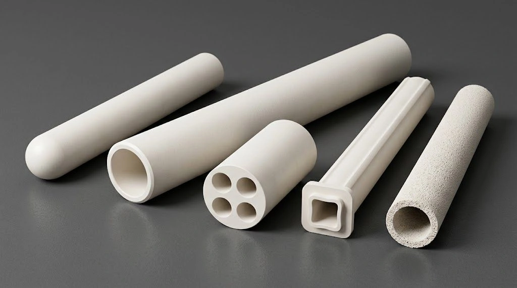
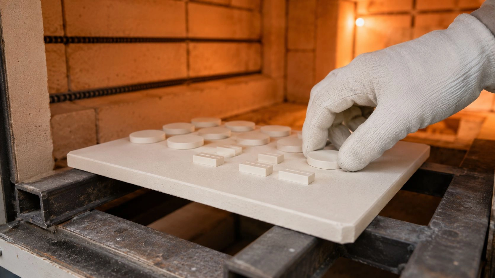
An alumina tube for thermal shock must balance heating rate, wall thickness, and stress.
Slow, optimized ramps control temperature gradients, reduce tensile stress, and extend operational life.
This article explains how heating protocols, microcrack kinetics, and process design determine the durability of an alumina tube for thermal shock.
Thermal Gradients and Transient Stresses Governing Alumina Tube for Thermal Shock Failure
Rapid heating in an alumina tube for thermal shock causes transient stress due to steep temperature gradients.
The relation σ = EαΔT/(1−ν) links stress to surface-core temperature difference. Grade-typical teaching values often cited for dense alumina are E ≈ 370 GPa, α ≈ 8×10⁻⁶ /°C, and ν ≈ 0.22 — grade- and temperature-dependent; confirm on TDS.
Every 1 °C of gradient therefore generates on the order of ~2.5 MPa/°C of stress under that teaching set (again confirm on TDS). As an illustrative case — geometry- and furnace-dependent, not a universal prediction — when rates are aggressive relative to wall, a mid-thickness wall can develop a large surface-core ΔT and push transient stress near typical flexural strength bands (often cited ~350–400 MPa teaching).
Field failures often occur during heat-up when ramps are aggressive relative to wall thickness.
Finite element modeling shows stress scales with both heating rate and L² (wall thickness squared).
Hence thicker walls typically see higher transient ΔT for the same ramp than thinner walls — slow the ramp as wall increases.
Temperature Gradient Evolution in Alumina Tube Heating
Transient heat conduction dictates how quickly a core follows surface temperature.
In an alumina tube for thermal shock, the time constant scales with ρCpL²/k.
At fast rates, surface temperatures rise faster than the core, producing high ΔT early in the heat-up.
Time-Dependent Stress Accumulation
Peak stress appears partway into heating before equilibration.
Monitoring this interval helps control heating protocols for alumina tube for thermal shock and limit microcrack activation.
Wall Thickness Influence on Thermal Stress
Doubling wall thickness can roughly quadruple transient ΔT if the heating rate is held constant.
For each alumina tube, rate adjustment is essential to keep surface-core ΔT within the process control band defined on the process RFQ — not a universal acceptance gate.
Core Stress Parameters for Alumina Tube for Thermal Shock
Teaching / grade-typical parameters — confirm on TDS; not factory-calibration claims.
| Parameter | Symbol | Value | Units | Relationship |
|---|---|---|---|---|
| Young’s Modulus | E | ~370 | GPa | Directly proportional to σ |
| CTE | α | ~8.0×10⁻⁶ | 1/°C | Higher α → higher σ |
| Poisson’s Ratio | ν | ~0.22 | – | σ ∝ 1/(1−ν) |
| Wall Thickness | L | 2–6 | mm | ΔT ∝ L² |
| Heating Rate | dT/dt | screening band | °C/min | ΔT ∝ dT/dt |
Controlled Heating Protocols Mitigating Microcrack Nucleation in Alumina Tube for Thermal Shock
Maintaining moderated heating rates for alumina tube for thermal shock keeps surface-core ΔT inside a manageable control band.
This helps keep tensile stress below fracture strength and suppress microcrack nucleation.
A teaching form of the critical-rate limit is rate = k(σf/Eα)(1−ν)/L² — so thicker walls need slower ramps. The wall→°C/min values below are illustrative screening only: wall-, grade-, and furnace-dependent, and not acceptance gates — confirm on process RFQ.
Slower, controlled ramps reduce microcrack nucleation density and acoustic-emission activity relative to aggressive single-stage heat-ups — confirm on duty data rather than treating any single rate as a contract SLA.
Critical Heating Rate Values Based on Wall Thickness
Illustrative screening table — wall / grade / furnace dependent; not acceptance gates; confirm on process RFQ (aligned with crack/failure-mode screening practice).
| Wall Thickness (mm) | Thermal Conductivity (W/m·K) | Flexural Strength (MPa) | Screening Heating Rate (°C/min) |
|---|---|---|---|
| 2 | 10–15 | ~360 | 12–15 |
| 4 | 10–15 | ~360 | 6–8 |
| 6 | 10–15 | ~360 | 3–4 |
Rate-Dependent Microcrack Formation
In an alumina tube for thermal shock, steeper ramps raise nucleation activity.
Rate reductions cause sharp drops in microcrack events as σ falls below a threshold stress band (teaching order ~200 MPa — confirm on grade/TDS).
Nonlinear Relationship Between Stress and Crack Nucleation
An Arrhenius-type rate R ∝ exp[(σ−σth)/σc] explains why small rate changes can matter.
Even a modest drop in °C/min can cut nucleation activity substantially for alumina tube for thermal shock systems — confirm on duty instrumentation.
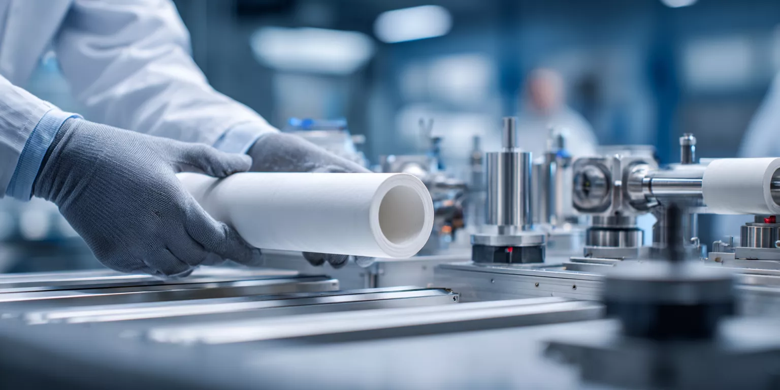
Microstructural Damage Accumulation Versus Heating Rate in Alumina Tube for Thermal Shock
Aggressive ramps accelerate crack growth per cycle; slower controlled ramps slow growth and keep cracks more isolated.
Slower, controlled ramps can extend cyclic life and cut unplanned downtime — confirm on duty data; do not treat any published cycle count as a contract SLA.
Damage evolution is often discussed with a Paris-law framework da/dN = C(ΔK)ᵐ — framework only; not calibrated to production parts.
Crack Growth Rate and Life Correlation
Qualitative screening — not calibrated life tables.
| Heating Rate Regime | Crack Growth Tendency | Cyclic Life Tendency | Crack Density Tendency |
|---|---|---|---|
| Aggressive / fast | Higher per-cycle growth | Shorter | Higher |
| Moderate multi-stage | Reduced growth | Longer | Moderate |
| Slow controlled | Lowest growth | Longest (duty-confirmed) | Lowest |
Crack Coalescence and Failure Timing
Cracks coalesce when spacing approaches a few crack lengths.
Faster rates raise density and interaction probability, while controlled heating keeps cracks isolated and stable.
Time–Temperature Damage Mapping
A TTT-style map for alumina tube for thermal shock defines three regimes:
Fast damage (aggressive ramps), moderate (staged ramps), and slow (controlled multi-stage) where cyclic life is longest when confirmed on duty data.
Interaction Between Heating Protocols and CTD Limits in Alumina Tube for Thermal Shock
Graduated heating profiles improve usable critical temperature difference (CTD) utilization versus constant aggressive rates.
Multi-stage control typically supports longer cyclic service at a given ΔT duty than a single constant rate — confirm on process RFQ and duty data.
Effective-CTD relations of the form CTD_eff = CTD × [1 + β(R₀/R − 1)] are teaching frameworks only — not calibrated coefficients for production tubes.
Heating Rate Protocol Comparison for Alumina Tube for Thermal Shock
Illustrative protocol screening — wall / grade / furnace dependent; not life or CTD acceptance gates.
| Protocol | Heating Rate Pattern | Hold | ΔT Tendency | Service-Life Tendency |
|---|---|---|---|---|
| Constant aggressive | Single fast ramp | None | Highest | Shortest |
| Conservative single | Single slow ramp | None | Lower | Improved |
| Two-stage | Slow → slower | Optional | Controlled | Better |
| Three-stage | Staged mid/high/low | Optional | Tighter | Better |
| Optimized multi-stage | Ramp / hold / ramp | Yes | Lowest peaks | Best when duty-confirmed |
CTD Utilization and Cost Benefit
Optimized heating can extend usable ΔT headroom without changing grade and reduce unplanned replacement downtime — confirm on duty data; do not treat any cost-% or life-% figure as a contract SLA.
Stress Concentration Factor Reduction
Graduated ramping reduces peak stress concentration relative to abrupt ramps, limiting localized cracking in an alumina tube for thermal shock.
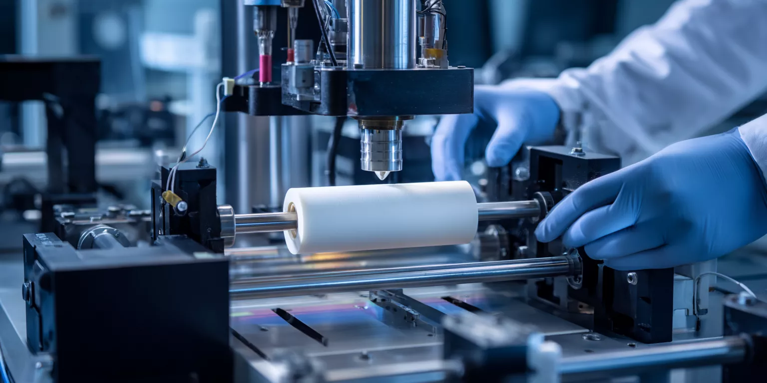
Service Life Optimization Protocols for Industrial Alumina Tube for Thermal Shock Processes
Slower, controlled ramps can extend cyclic life when heating, holding, and cooling are integrated — confirm on duty data rather than quoting a fixed life-% gain.
A five-element protocol includes controlled ramps, holds, and adaptive feedback keyed to measured ΔT.
Five-Step Optimization Framework
Illustrative screening protocol — wall / grade / furnace dependent; target ΔT bands are control guides, not acceptance gates; confirm on process RFQ.
| Stage | Temperature Range (°C) | Rate (°C/min) | Hold (min) | Target ΔT (°C) |
|---|---|---|---|---|
| Initial Ramp | 25–400 | 3–5 | – | < 100 |
| Mid Ramp | 500–900 | 8–10 | – | < 120 |
| Final Ramp | 900–1200 | 2–4 | – | < 100 |
| Intermediate Hold | 600 / 1000 | – | 15–30 | < 60 |
| Cooling | 1200–400 | slower than heating | Short | < 120 |
Real-Time Adaptive Control
Three thermocouples (surface, mid-wall, core) feed PLCs that slow the ramp whenever measured ΔT exceeds the process alarm band.
Dynamic hold insertion occurs when gradients are not converging as expected.
Predictive Maintenance via Damage Modeling
Using Miner’s rule Σ(ni/Ni) ≤ 1 as a framework only helps schedule replacement before cumulative damage reaches failure — not a calibrated plant SLA.
This approach balances longevity and process continuity for alumina tube for thermal shock operations.
Conclusion
Heating rate optimization extends alumina tube for thermal shock service life and reduces failure costs when ramp, wall, and ΔT are written into the process card.
Next step: lock wall thickness, grade, max ramp, hold strategy, and ΔT alarm into your RFQ. Review stock and custom alumina tubes, or send a wall / ramp-protocol RFQ through custom services.
Related reading
- Controlled heating rates for alumina tubes in vacuum furnaces — vacuum-furnace companion on staged ramp / hold to protect tube life under controlled atmosphere.
- Insulating alumina tube thermal-shock resistance parameters — parameter checklist for thermal-shock duty on insulating alumina tubes (pairs with the ramp / ΔT RFQ fields above).
- SEM-EDX and XRD monitoring of high-purity alumina tubes — post-cycle microstructure and phase checks after aggressive thermal cycling (monitoring companion, not a purity-procurement guide).
FAQ
How do heating rates affect alumina tube for thermal shock stress levels?
Higher heating rates create larger ΔT, raising surface stress toward flexural strength.
Controlled rates keep stress below the fracture threshold and support longer cyclic life — confirm on duty data.
What are cost impacts of optimized heating protocols for alumina tube for thermal shock?
Instrumentation and recipe changes are usually modest versus the cost of unplanned tube replacement and downtime — quantify against your furnace duty rather than a generic savings %.
How can industrial users verify thermal gradients in alumina tube for thermal shock?
Install three thermocouples at surface, mid-wall, and core to record real-time ΔT and trigger adaptive control actions.
Why choose alumina tube for thermal shock over other ceramics?
While zirconia offers higher toughness, an optimized heating protocol lets an alumina tube for thermal shock meet many thermal-cycling duties at lower material cost — select by duty RFQ, not brand claims.
References:
- Nucleation rate background — materials-science context for microcrack initiation under thermal stress.
- Interaction probability — engineering context for crack coalescence under rising crack density.
- Miner’s rule — linear damage framework for maintenance scheduling (framework only; not plant-calibrated).