Thermocouple Immersion Depth and Stem Conduction Error
Thermocouple immersion depth is adequate when the measuring junction sits in the intended temperature zone and heat transfer along the installed assembly stays within the measurement's allowable error. A shallow installation can let a cooler mounting region influence the sensing area. The required depth depends on the tube, thermocouple, thermal environment, and accuracy target. Establish the geometry and furnace temperature profile, then verify the result with an appropriate independent comparison. A reading change when a used probe is pushed farther in does not, by itself, prove stem conduction error.
This matters when a replacement assembly fits its port but reads differently from the old one. Overall tube length may be unchanged while the mounting stop, closed tip, or junction position has shifted. A longer tube may place the junction beyond the actual process location of interest. Before ordering a different length, define what temperature the reading must represent, how much disagreement is acceptable, and where each physical component sits relative to the furnace wall and hot zone.
Which Length Is Actually Immersed in the Measurement Zone?
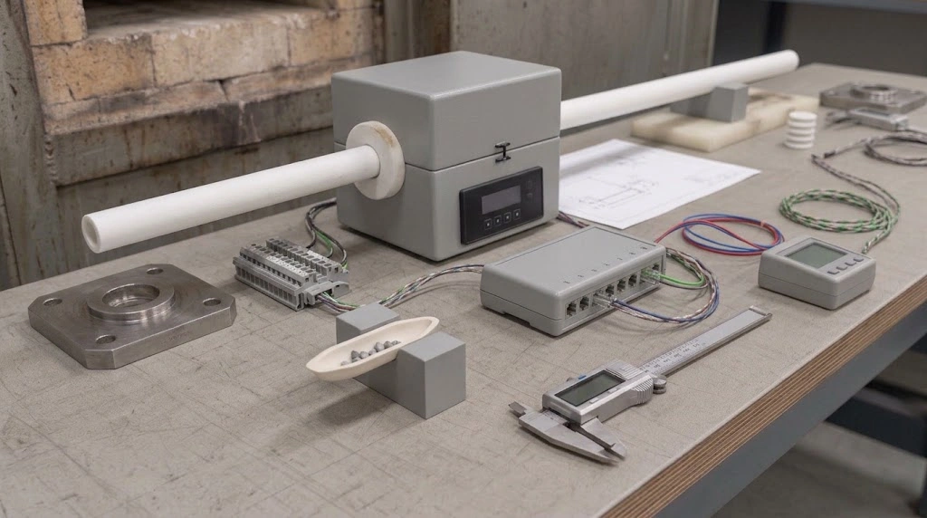
Draw the installed assembly on one axial line. Mark the furnace wall or process boundary, the seating face of the flange or threaded fitting, the tube's closed end, and the thermocouple measuring junction inside the tube. Add the start and end of the target measurement zone. Do this for the as-installed condition, not merely the nominal catalogue geometry.
Mounting-face datum, inserted length, and external projection
Use a defined mounting-face datum for dimensions. Overall tube length runs from one physical end of the ceramic part to the other. Inserted length runs from the agreed mounting face into the process. External projection is the part outside that face. Depending on the port design, the furnace wall, flange seat, and actual thermal boundary may lie at different axial positions. State each separately on the drawing.
Measure the seating feature and check whether a stop collar, compression fitting, thread adjustment, or gasket changes the seated position. A replacement tube with the same overall length can have a different hot-end position if its interface geometry changes. Record whether the tube can slide, whether the fitting is repeatable after maintenance, and whether supports constrain the assembly when heated. Do not assume that the visible external length alone establishes the depth inside the furnace.
Junction-to-closed-tip position and target hot zone
The ceramic tip is not necessarily the sensing junction. Confirm that the thermocouple is fully seated as intended and establish the junction's distance behind the closed end. A junction near the furnace-wall gradient can miss the intended uniform region even when much of the tube appears inserted. A very deep junction may instead sample a different part of the load or process. The measurement specification therefore needs both the target zone and the junction location, with a datum linking them.
If the furnace has a mapped axial profile, attach it and mark the junction. Otherwise, plan an independent mapping or comparison before assigning the discrepancy to insufficient immersion.
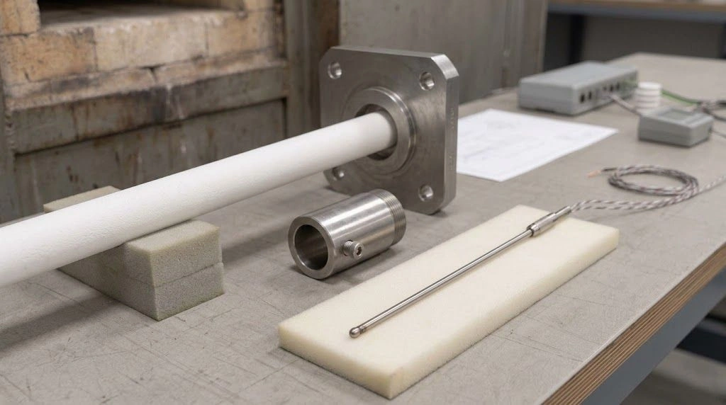
Define the mounting datum and sensing position before treating overall tube length as immersion depth.
How Does Stem Conduction Alter a Thermocouple Reading?
An installed sensor crosses a hot boundary. Heat can flow along thermocouple wires, a sheath, the ceramic tube, fittings, and supports toward a cooler external region; the direction can reverse when the external region is hotter than the measurement zone. That heat flow can change the local temperature of the assembly near the junction and its surroundings. The BIPM Guide to Secondary Thermometry describes immersion and heat-leak effects and gives an approximate model in which the immersion-related effect falls as immersed length increases.
Conductive paths through the assembly and mounting
Trace the heat path rather than attributing the error to one material. The wire, internal insulation, outer tube, metal fitting, and mechanical support can each connect regions at different temperatures. Their dimensions, thermal contact, and surrounding gas or process affect the result. So do the temperature difference across the boundary and heat transfer from the process to the tip. A slender sensor within a large ceramic protection tube does not automatically behave like the bare sensor diameter; the surrounding assembly changes the thermal boundary.
For a practical first review:
-
Locate the intended junction position. Compare the as-installed geometry with the known or measured hot zone.
-
Identify possible heat paths. Note the tube, wire, fitting, supports, and cooler or hotter regions connected to them.
-
State the allowable error. Decide what measurement uncertainty or process tolerance the assembled installation must meet.
-
Plan a controlled comparison. Use a suitable reference and known locations before selecting a revised length or correcting a reading.
The ceramic supplier can review feasible geometry, fit, and service compatibility for ceramic thermocouple protection tubes. The measurement specialist must assess whether the assembled installation meets the temperature-measurement requirement. Changing the tube alone does not establish a numerical reduction in error.
Why gradient and operating condition matter
The same assembly can behave differently at a steady soak and during a rapid ramp. The tube and junction take time to follow a changing process temperature; distinguish this response from a steady heat leak. Record process load, time at temperature, and reference position when comparing readings.
Thermocouple voltage is generated along the two conductors where temperature gradients occur, rather than at a single point inside the junction. The BIPM guide explains this operating principle and its consequence: nonuniform wire properties can make the result depend on which part of the wire lies in a gradient. Stem conduction and thermoelectric inhomogeneity can therefore coexist. The apparent direction and size of a discrepancy should be established by measurement, not assigned from a generic illustration.
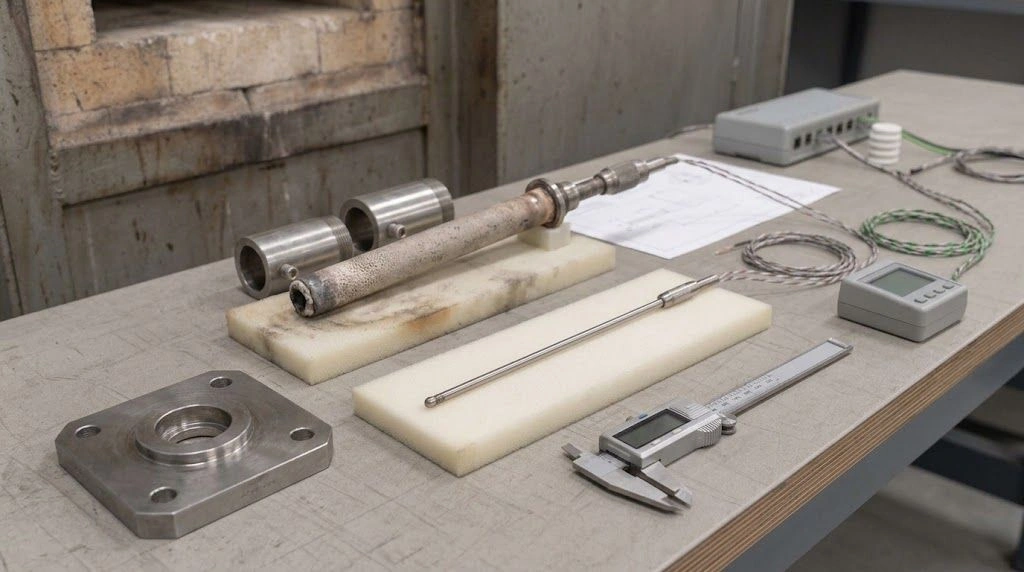
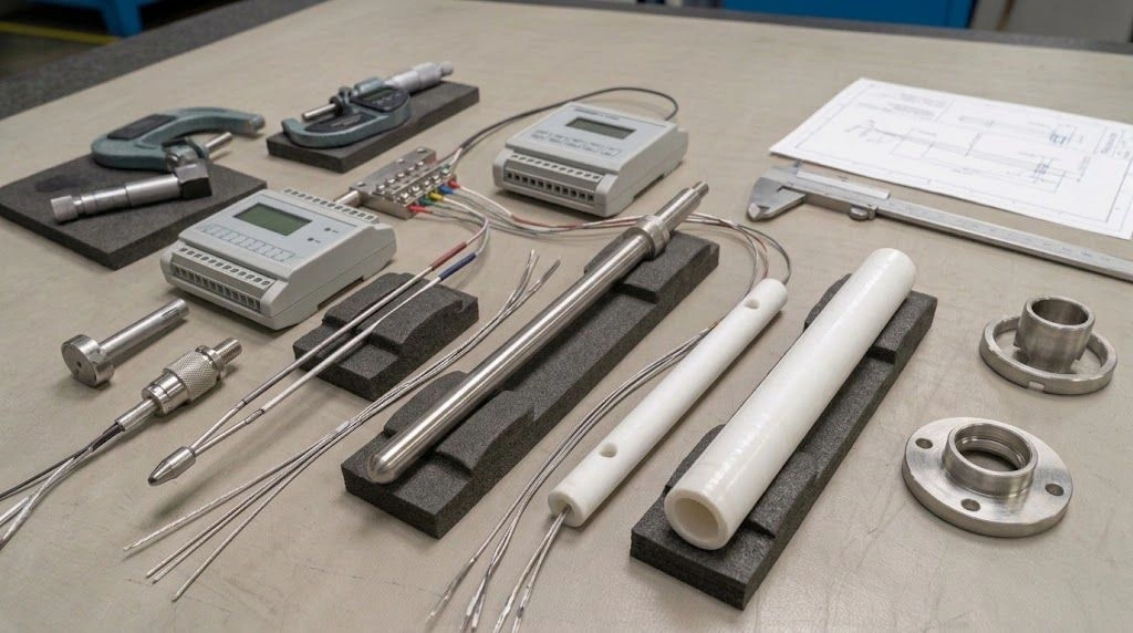
Wires, tube, and mounting hardware form separate parts of the installed heat path.
Is the Difference Stem Conduction, Furnace Nonuniformity, or Thermocouple Inhomogeneity?
Pushing a probe inward changes several things at once. Its junction may enter a genuinely different furnace temperature. A previously altered section of thermocouple wire may move from one part of the axial gradient to another. The conductive path to the mounting region also changes. Thus, a reading that changes with insertion is a useful observation but an ambiguous diagnosis. BIPM explicitly cautions against using an immersion change alone to estimate thermocouple immersion error; for thermocouples previously used at elevated temperature, changing immersion conditions can itself change the thermocouple's state.
| Observed difference | Possible mechanism | Check before assigning cause | Next decision |
|---|---|---|---|
| Junction is near the wall or edge of the hot zone | Insufficient effective immersion or wrong measurement location | Compare the drawing and junction position with an independently established axial profile | Review installed length and mounting datum |
| Reading changes after moving the probe | Actual temperature differs at the new location | Check the profile and both junction positions | Restore comparable measurement locations |
| Reading changes after moving a used probe | Inhomogeneous wire occupies a different gradient | Review exposure and calibration history; use an appropriate comparison | Do not label the change stem conduction alone |
| Difference is strongest during a ramp | Thermal response, position, and heat paths may all contribute | Compare behavior during a defined stable hold and during the ramp | Assess the complete assembly and transient requirement |
| Tip position changes after maintenance | Stop, fitting, or projection is not repeatable | Measure as-left geometry and inspect the mounting feature | Specify a repeatable seating position |
Research by Hill and Gee on thermocouple inhomogeneity examines how spatial variation of the Seebeck coefficient affects calibration uncertainty. That mechanism is especially relevant to a used sensor exposed to nonuniform temperatures. Calibration history helps, but a certificate obtained under one temperature distribution does not automatically describe every new installation gradient.
An independent reference needs a defined sensing location. Control position and process state; two different furnace locations cannot isolate instrument error. Check thermocouple type, instrument configuration, reference-junction compensation, extension wiring, and recent maintenance. NIST's thermocouple calibration uncertainty work illustrates why the calibration method and uncertainty elements should be stated rather than assuming a reference reading is exact.
If the process has a narrow uniform zone, make the location decision first. If stable, position-matched readings still disagree, evaluate the sensor and electronics. If evidence then points to a heat leak from the installed geometry, consider a deeper insertion or revised mounting arrangement and verify it as an assembly. Document all changes so that a new tube length is not mistaken for proof that the original cause was known.
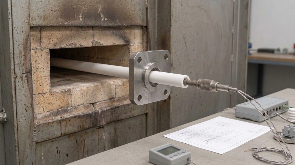
A position-matched reference comparison helps separate an installation question from other measurement errors.
What Immersion Depth Is a Defensible Starting Point?
The BIPM guide gives conservative reference ratios tied to particular accuracy examples. It recommends immersion greater than ten times the diameter of the thermocouple, thermowell, or drywell, whichever is greater, for a 1% accuracy example. For a 0.01% accuracy example, it gives greater than thirty times that largest diameter. The guide also discusses the underlying heat-transfer model and notes that behavior differs across thermal environments. These ratios are starting points for review, not universal industrial furnace minimums or guarantees for a ceramic tube assembly.
| Measurement objective in the BIPM example | Conservative reference immersion | What the furnace installation still requires |
|---|---|---|
| About 1% accuracy | Greater than 10 × the largest relevant diameter | Confirm the target zone, complete assembly geometry, operating gradient, and site acceptance criterion |
| About 0.01% accuracy | Greater than 30 × the largest relevant diameter | Obtain a suitable high-accuracy measurement and uncertainty review |
| Neither example matches the actual duty | No transferable universal ratio | Establish acceptance from the process tolerance, installed assembly, thermal environment, and reference comparison |
Identify the controlling diameter in the BIPM comparison: thermocouple, thermowell, or drywell, as applicable. A larger surrounding ceramic tube and its mounting require an installation-specific assessment. The ratio alone cannot establish whether the junction reaches the target zone; check the furnace profile and junction-to-tip distance.
If the port cannot position the junction in the intended region, address layout first. If space or supports prevent deeper insertion, ask a measurement specialist to assess the feasible installation. Define an acceptance test with process condition, reference method, location, allowable difference, and repeatable assembly position.
What Should the Protection-Tube Drawing and RFQ Show?
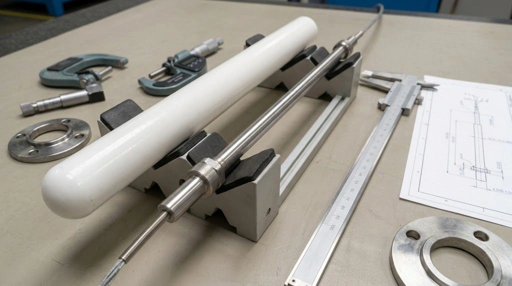
Send a drawing that links the ceramic component to the complete installation. Mark the furnace-wall or process-interface datum and the mounting seating face. Specify tube overall length, inserted length from that face, external projection, and distance from the closed end to the thermocouple junction. Show the target measurement zone and any known axial temperature profile. If the profile is not known, state how it will be established during commissioning.
List tube OD, ID, wall thickness, closed-end shape and thickness if controlled, fitting or flange dimensions, seating and stop features, support points, and clearances for the sensor and thermal expansion. State whether the part is horizontal or vertical and whether contact with a wall, load, or support must be avoided. Include tolerances only where they matter to fit, junction location, repeatability, or inspection, with the chosen datums clearly marked.
Give the supplier the service conditions: normal and peak temperature, atmosphere, process vapors or deposits, thermal cycling, mechanical contact, quantity, and whether a sample fit check is planned. Provide the thermocouple type and assembly drawing where available. Ask the ceramic supplier to confirm manufacturable dimensions and material suitability for the stated conditions. Keep the assembled measurement check in the site or calibration plan: specify the reference location, operating state, allowable error, and record of the as-left junction position.
Finally, make replacement repeatable. A fixed seating face or documented stop dimension lets maintenance restore the same measuring location. Record the as-built tube dimensions and as-installed projection, then compare readings under the defined condition. If the new assembly still disagrees, revisit the temperature profile, wire condition, and measurement circuit. An RFQ for tube length is complete only when the resulting junction position and verification method are unambiguous.