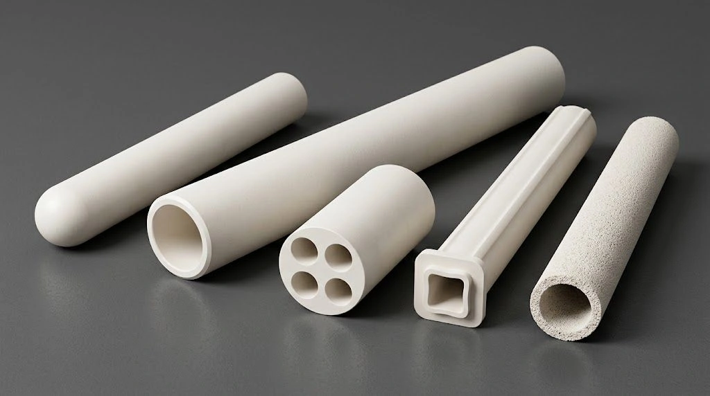
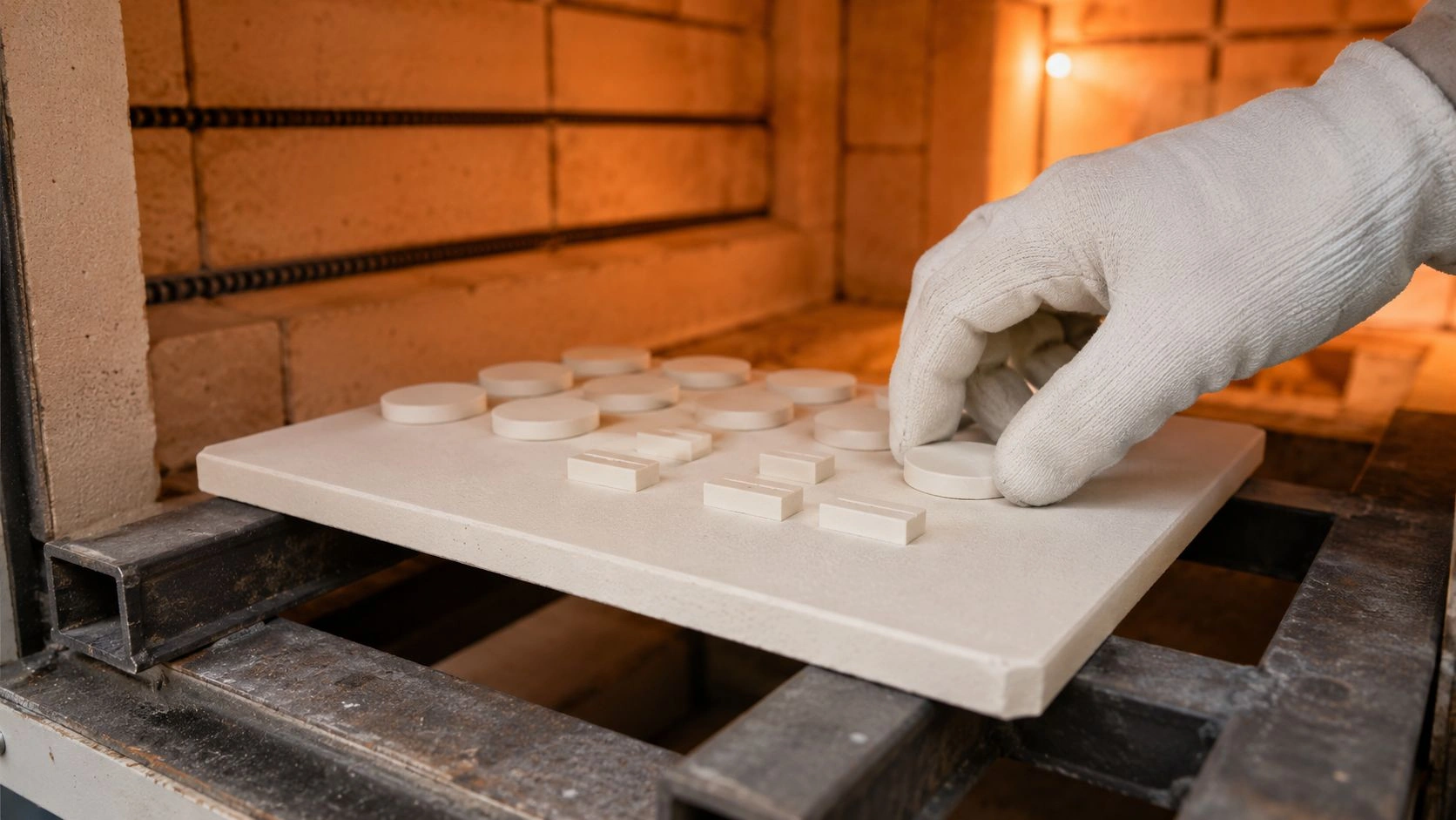
Cutting an alumina tube without the right tooling and setup often produces chips, dimensional drift, or latent edge damage. Alumina’s hardness and brittleness demand diamond abrasives, stable fixturing, consistent coolant, and a controlled feed — plus a clear stop rule for when field cutting should stop and a factory-cut length RFQ should start.
This guide stays on the cold-cutting axis: diamond tools, fixturing, coolant, end-face checks, and the when-NOT-to-cut decision. It is not a furnace heating-rate or crack-failure encyclopedia.
Understanding the Material: What Makes Alumina Tubes Difficult to Cut
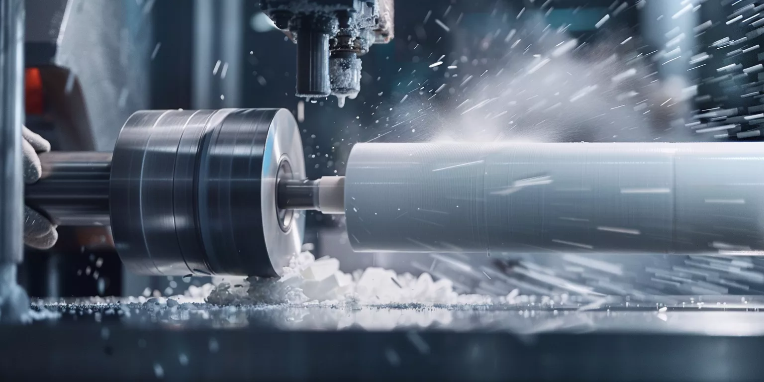
The intrinsic characteristics of an alumina tube control how it responds to mechanical load during cutting. Its crystalline hardness and low toughness make fracture propagate faster than most metal-cutting habits expect.
High Hardness and Brittleness
Mohs hardness in the ~8.5–9 band (grade-typical teaching; confirm on TDS) is why diamond tooling is mandatory and why dry, unsupported cuts accelerate tool wear and edge chip-out. Poor support, aggressive feed, or non-diamond tools raise reject risk — treat that as a process control problem, not a cosmetic one.
Edge Damage and Latent Defects
Invisible edge damage can continue to matter after the cut. Screen cut ends under magnification when the duty is sealing- or high-temp-critical, and specify flatness / squareness / length / finish on the drawing rather than relying on an undrawn shop “looks OK” call.
Heat Build-Up During Cutting (Coolant Context)
Alumina’s thermal conductivity is modest, so frictional heat concentrates at the kerf. Dry cutting spikes surface temperature and chip-out risk; the exact ΔT is tooling-, coolant-, and feed-dependent and is not a universal limit. Steady coolant and moderated feed remain the practical controls when a field cut is unavoidable.
Material Properties — Teaching Snapshot
Grade-typical teaching values — confirm on TDS; not cutting-contract SLA.
| Property | Typical band | Cutting implication |
|---|---|---|
| Hardness (Mohs) | ~8.5–9 | Diamond tooling required |
| Flexural strength | grade-typical TDS band | Edge damage can reduce usable strength — confirm on duty+COA |
| Thermal conductivity | modest vs metals | Coolant needed to limit kerf heat |
| CTE | grade-typical TDS band | Uneven heating during dry cuts raises stress |
Tools Required for Cutting Alumina Ceramic Tubes
Specialized tooling is required because conventional metal-cutting blades cannot engage alumina safely.
Diamond Cutting Wheel or Diamond Saw
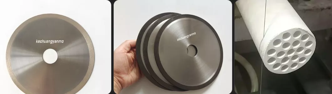
Continuous-rim diamond wheels usually give the steadiest thin-wall cuts; segmented rims can work on thicker sections but chatter more. Non-diamond abrasives raise chip-out and reject risk and should not be used for high-purity alumina tubes.
Cooling System for Thermal Control
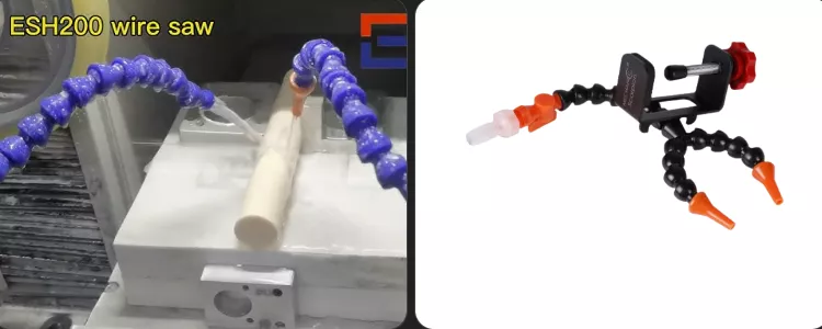
Water-based coolant dissipates kerf heat more consistently than air alone, flushes grit, and lowers airborne dust. Dry cutting spikes surface temperature and chip-out risk — treat coolant as mandatory for structural cuts, not optional.
Tube Holding Fixtures for Vibration Reduction
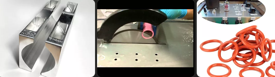
Elastomer-backed or dual-point supports spread grip load and cut oscillation. Unsupported or single-point clamps raise bending stress and reject risk, especially on long or thin-wall tubes. Better fixturing and coolant reduce damage.
Tooling Comparison (Qualitative)
| Tool / setup | Effectiveness | Reject risk | Notes |
|---|---|---|---|
| Diamond wheel (continuous rim) | High | Lower when feed/coolant controlled | Preferred for thin walls |
| Diamond saw (segmented) | Medium | Medium | Acceptable on thicker sections |
| Non-diamond abrasives | Very low | Very high | Not suitable |
| Water coolant + multi-point fixture | High | Lower | Core process controls |
Step-by-Step Procedure: How to Cut Alumina Ceramic Tubes Safely and Properly
A disciplined sequence keeps stress, heat, and dimensional drift under control.
Step 1: Marking and Surface Preparation
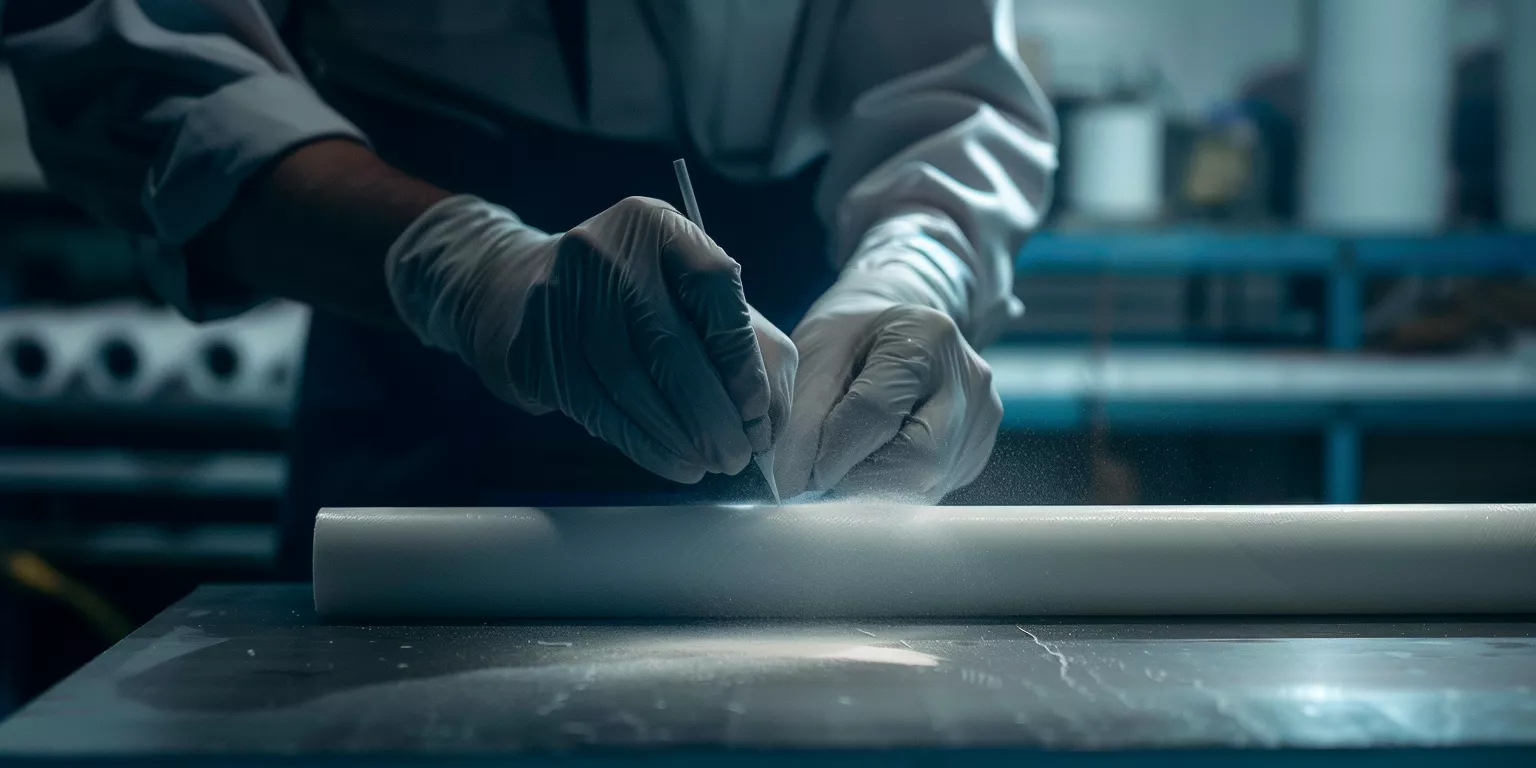
Mark the cut plane under stable lighting and clear debris from the contact zone. A light protective wrap at the kerf line can reduce edge chip-out; treat mark accuracy as the first RFQ/fitment control, not a trivial step.
Step 2: Stabilizing the Tube and Minimizing Vibration
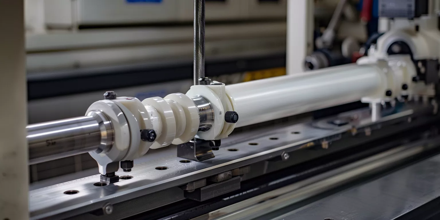
Use dual-point (or multi-point on long tubes) support so the blade axis stays aligned with the tube centerline. Poor support raises reject risk; verify support before the wheel touches ceramic.
Step 3: Selecting an Appropriate Feed Rate

Advance slowly and evenly. Erratic feed spikes torque, kerf wander, and chip-out. Feed is tooling- and geometry-dependent — lock a conservative rate on the process card rather than racing the cut.
Step 4: Managing Cooling Through the Cut
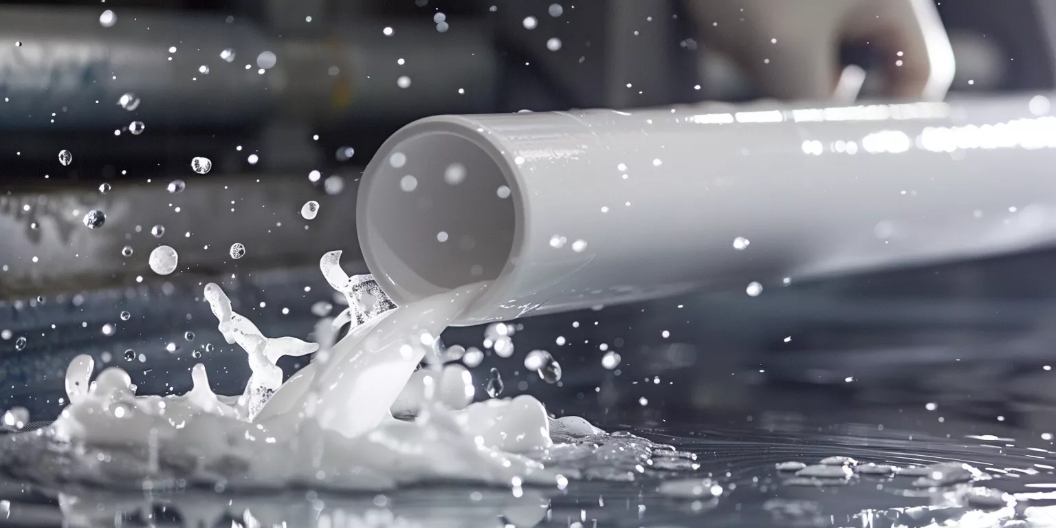
Keep coolant continuous at the kerf. Dry cutting spikes surface temperature and chip-out risk; interrupted flow recreates the same problem mid-cut.
Step 5: Finishing the Last Millimeters of the Cut

The breakaway zone carries the highest chip-out risk. Slow the feed and ease blade pressure for the final millimeters — do not force separation.
Step 6: Post-Cut End-Face Grinding and Cleanup
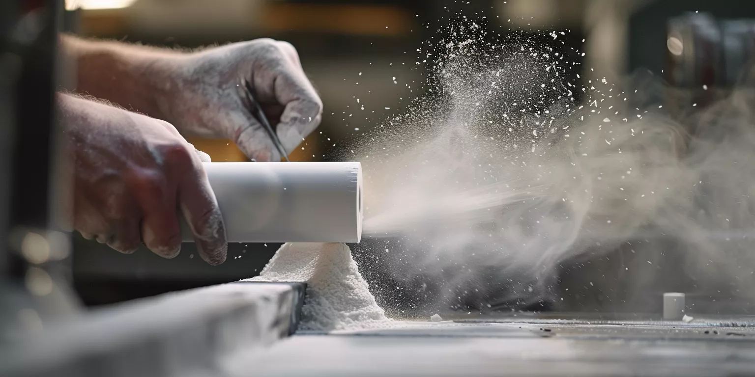
Light diamond finish on the end face improves seating and sealing. Clear bore debris before install. Specify flatness / squareness / finish on the drawing when the interface is critical.
Common Mistakes to Avoid When Cutting Alumina Tubes
- Non-diamond tools — raise chip-out and reject risk; diamond only.
- Dry cutting — spikes surface temperature and edge damage; keep coolant on.
- No / weak support — bending and chatter drive tapered kerfs and scrap; multi-point fixture first.
| Mistake | Failure mode | Control |
|---|---|---|
| Non-diamond tool | Uncontrolled chipping | Continuous-rim diamond |
| Dry cut | Heat spike + edge damage | Continuous water coolant |
| Unsupported tube | Bending / tapered kerf | Dual- or multi-point fixture |
Engineering Quality Checklist: How to Inspect a Cut Alumina Tube
Use the checks below as drawing- / inspection-class screening — not undrawn acceptance gates. Put flatness, squareness, length, kerf finish, and magnification criteria on the drawing + RFQ.
- End-face flatness & perpendicularity — confirm seating against seal/fixture requirements on the drawing.
- Kerf / edge condition — look for chip-out and latent edge damage; magnify when duty is critical.
- Length / OD-ID fit — verify against drawing length and interface stack-up.
| Inspection category | How to use | Notes |
|---|---|---|
| End-face flatness | Drawing- / inspection-class screening | Specify on drawing; not a universal gate |
| Perpendicularity | Drawing-class screening | Affects axial seating |
| Kerf finish | Inspection-class screening | Unstable feed leaves rough texture |
| Edge damage screen | Magnification when duty-critical | Latent damage ≠ cosmetic only |
| Length deviation | Drawing-class screening | Confirm on drawing + RFQ |
When You Should NOT Cut Alumina Tubes Yourself
Stop field cutting and RFQ a factory-cut length when any of the following apply:
- Ultra-tight drawing tolerances — length / end-face / finish bands that bench tools cannot hold repeatably.
- Multi-bore or thin-wall geometries — vibration and uneven coolant make scrap likely.
- High-temperature or high-load duty — pre-existing cut damage can reduce high-temperature reliability — confirm on duty+COA; prefer drawing-controlled factory cuts.
| Scenario | Risk | Preferred path |
|---|---|---|
| Tight drawing tolerances | Fit / seal loss | Factory-cut length RFQ |
| Multi-bore / thin wall | Channel or wall crack-out | CNC / diamond grind under fixture |
| High-temp / load duty | Latent edge damage in service | Drawing-controlled factory cut + finish |
Industrial Alternative: Why Factory-Cut Lengths Are Usually Safer
Drawing-controlled factory cuts usually reduce handling-damage risk vs uncontrolled bench cuts. Industrial cells combine diamond tooling, rigid fixturing, metered coolant, and post-cut grind/lap that most benches cannot match.
| Criterion | Bench / field cut | Factory-cut (process-typical) | How to use the comparison |
|---|---|---|---|
| Kerf / edge finish | Highly operator-dependent | More repeatable under process control | Specify finish on drawing |
| Angular / length control | Wide scatter without metrology | Drawing-class / process-typical length control — confirm on drawing+RFQ | Not a contract SLA from this article |
| Heat / chip-out risk | Higher if dry or poorly supported | Lower with metered coolant + fixture | Qualitative process contrast |
| Micro-edge damage | Higher when uncontrolled | Usually lower after grind/lap | Confirm on duty+COA when critical |
A Smarter Alternative: If Cutting Is Difficult, Custom-Length Tubes May Be Better
When fixturing, coolant, or tolerance risk stays high, order to length instead of cutting on the bench. Custom-length production removes field kerf variables, keeps end-face finish under process control, and shortens install rework.
- Dimensional scatter drops when length is produced to drawing rather than sawn in place.
- Edge damage risk drops when grind/chamfer/lap are part of the same traveler.
- Procurement gets batch consistency across stations — write OD/ID/wall/length tolerance/end-face/qty into the RFQ.
Next Step: Factory-Cut Length RFQ (Neutral Process Path)
When manual cutting becomes uncertain, send a factory-cut length RFQ rather than forcing a bench cut. Ask for drawing-class / process-typical length control — confirm on drawing+RFQ — plus end-face finish and any chamfer/grind notes.
RFQ fields to lock: OD / ID / wall / length tolerance / end-face flatness & finish / grade / qty / duty notes.
Review stock and cut-to-length options on alumina tubes, or route a custom-cut length RFQ through custom services.
Conclusion
Diamond tooling, multi-point fixturing, continuous coolant, careful breakaway, and end-face finish checks keep field cuts usable. When tolerances, multi-bore geometry, or duty risk exceed bench control, stop cutting and RFQ a factory-cut length.
Related reading
- Grinding processes for precision-ground alumina tubes — how post-cut grind and drawing tolerances turn a kerf into a sealable end face.
- Alumina ceramic machining methods map — which machining routes fit cut, grind, and finish operations on alumina parts.
- Specification consistency and batch QC for alumina tubes — how lot-level spec consistency and inspection keep cut/finished tubes interchangeable across batches.
FAQs
What is the biggest risk when cutting an alumina tube manually?
Brittle chip-out and latent edge damage from vibration, dry heat, or uneven force. Poor support and non-diamond tools raise reject risk even when the exterior still looks intact.
Why does the alumina tube require coolant during cutting?
Coolant limits kerf heat, flushes grit, and reduces chip-out. Dry cutting spikes surface temperature and edge-damage risk — tooling-/feed-dependent, not a single universal ΔT limit.
Can general metal-cutting blades be used for alumina tubes?
No. Alumina’s hardness exceeds standard blades; non-diamond tools raise chip-out and reject risk. Use diamond abrasives only.
How do I know if my cut alumina tube is acceptable for use?
Check end-face seating, kerf/edge condition, and length against the drawing. Use magnification when duty is critical. Treat checklist numbers in older shop notes as screening only — put acceptance on the drawing + RFQ.
When should I RFQ a factory-cut length instead of cutting myself?
When drawing tolerances are tight, the tube is multi-bore or thin-wall, or the duty is high-temperature / high-load. Drawing-controlled factory cuts usually reduce handling-damage risk vs uncontrolled bench cuts.