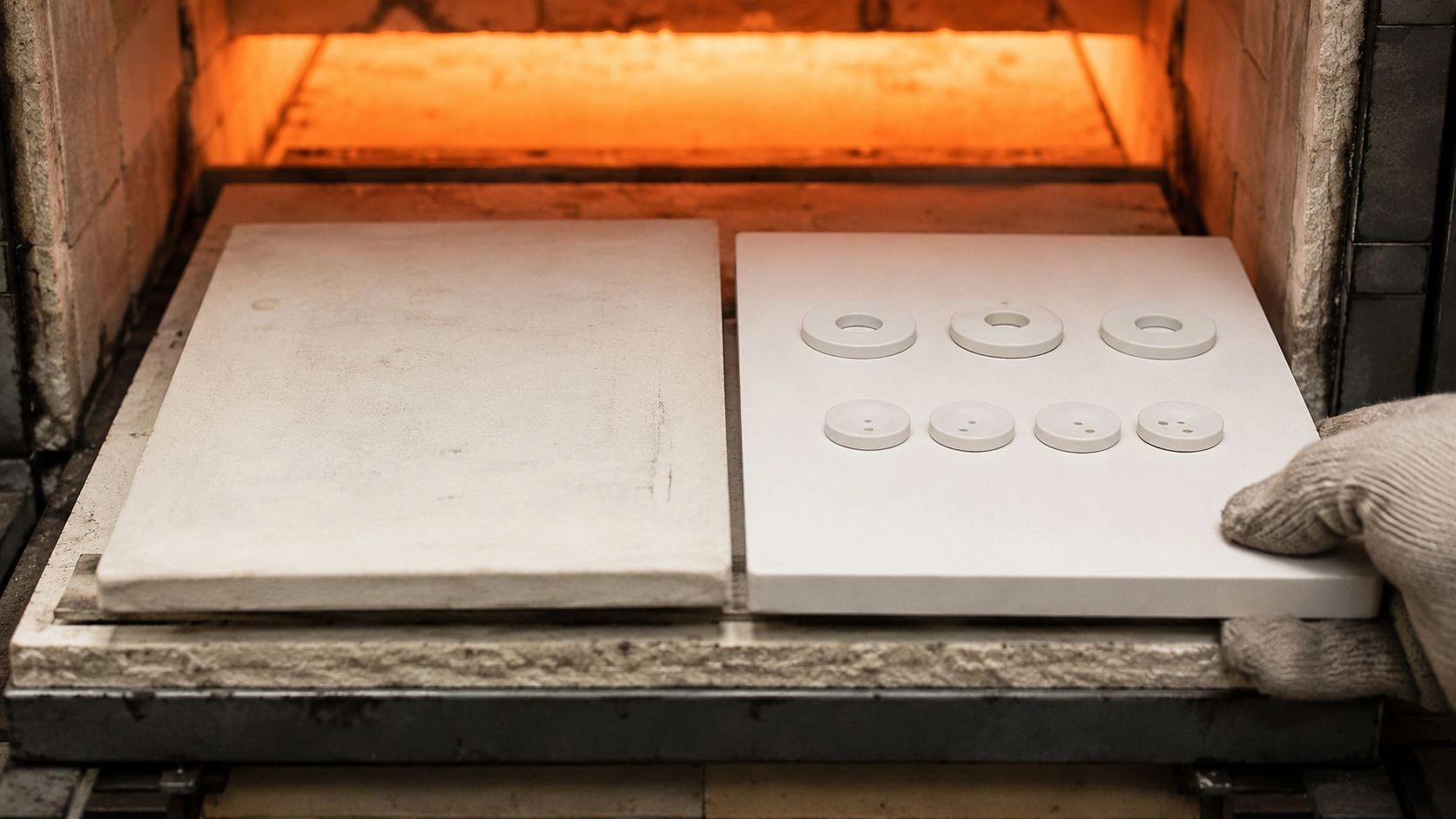
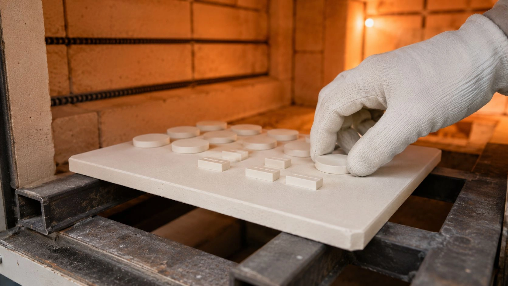
High-voltage vacuum systems frequently fail not because of circuit flaws, but because insulation structures degrade under coupled electrical, thermal, and mechanical stress beyond their design assumptions.
This article examines Alumina Plate as a structural and insulating material within vacuum equipment, high-voltage assemblies, and ceramic–metal sealed systems, addressing electrical stability, vacuum compatibility, mechanical integrity, and long-term reliability from an engineering perspective.
Accordingly, the discussion progresses from operating environments to material fundamentals, electrical insulation behavior, vacuum performance, structural mechanics, sealing interfaces, and finally engineering selection and customization practices, forming a complete decision framework for insulation and structural engineers.
Before material properties are evaluated, the actual operating environments of vacuum and high-voltage equipment must be defined, because environmental constraints shape every subsequent engineering decision.
Operating Conditions in Vacuum and High Voltage Systems
Vacuum insulation systems operate under combined electrical, thermal, and mechanical constraints that differ fundamentally from atmospheric or oil-immersed designs. Moreover, these constraints interact continuously, rather than acting independently, which amplifies the consequences of marginal material or structural choices.
In practice, Alumina Plate in such systems must withstand electric field concentration, suppressed convective cooling, residual gas effects, and mechanically constrained expansion. Therefore, understanding the operating environment establishes the boundary conditions for reliable insulation and structural design.
Vacuum Levels and Outgassing Constraints
In vacuum equipment, operating pressures typically range from 10⁻³ to 10⁻⁷ mbar, depending on application class and process requirements. At these pressures, even trace material outgassing becomes electrically and thermally significant.
Alumina Plate exhibits intrinsically low outgassing compared with polymeric insulators, provided that density exceeds 3.7 g/cm³ and open porosity remains below 0.1%. During initial pump-down, residual gases originate primarily from grain boundaries, adsorbed surface moisture, and machining residues rather than from the alumina lattice itself. Consequently, surface preparation and pre-bake conditions directly influence vacuum stability.
From field experience in vacuum interrupters and sealed chambers, engineers often observe that insufficiently baked alumina components extend pump-down time in a density-/surface-/geometry-dependent way — confirm conditioning on the RFQ, even when system leakage is absent. Therefore, vacuum compatibility is governed not only by material selection but also by conditioning discipline prior to assembly.
Electric Field Distribution and Insulation Stress
High-voltage insulation structures routinely experience electric field strengths in a 5–10 kV/mm screening band, particularly near edges, interfaces, and triple junctions. Under vacuum conditions, the absence of gas ionization changes breakdown behavior, shifting failure modes toward surface flashover and localized electron emission.
Alumina Plate supports high dielectric strength, typically around ~10 kV/mm on standard specimens (TDS typical; geometry-/atmosphere-dependent screening — confirm TDS+RFQ); however, local field enhancement at sharp edges or surface defects can reduce effective withstand — specify edge geometry and surface finish on the drawing. As a result, insulation failure rarely initiates through bulk breakdown, but instead originates at geometric discontinuities.
In practical insulation design reviews, structural engineers frequently trace premature flashover to insufficient edge radiusing or surface roughness above Ra 0.8 μm. Consequently, electric field management must be treated as a geometric problem as much as a material one.
Thermal and Mechanical Loads Under Sealed Conditions
Under vacuum, convective heat transfer is negligible, and thermal energy dissipates primarily through conduction and radiation. Accordingly, localized heat generation from dielectric losses or nearby conductors can raise alumina component temperatures by 40–70 °C above ambient without obvious external indicators.
Simultaneously, mechanical loads arise from sealing forces, mounting constraints, and differential thermal expansion between alumina and adjoining metals. Although Alumina Plate tolerates compressive stresses well, tensile stress generated by constrained expansion remains a critical risk factor. In sealed assemblies exceeding 100 mm in characteristic length, cumulative thermal mismatch can produce stress levels approaching 30–50 MPa at interfaces.
Therefore, operating environments impose coupled electrical, thermal, and mechanical demands that cannot be evaluated independently. Alumina Plate succeeds in these systems only when environmental interactions are explicitly accounted for during design.
Summary of Operating Environment Constraints
| Environmental factor | Typical range | Engineering implication | Design sensitivity |
|---|---|---|---|
| Vacuum pressure (mbar) | 10⁻³ to 10⁻⁷ | Outgassing control | High |
| Electric field strength (kV/mm) | 5–10 | Edge field concentration | Very high |
| Alumina dielectric strength (kV/mm) | ~10 (specimen typical) | Bulk insulation margin (screening) | Medium |
| Temperature rise (°C) | 40–70 | Thermal stress buildup | High |
| Interface stress (MPa) | 30–50 | Crack initiation risk | High |
Before electrical and vacuum behavior can be evaluated quantitatively, the intrinsic material characteristics of Alumina Plate must be clarified, because insulation reliability ultimately originates from ceramic microstructure rather than nominal specifications.
Material Structure and Intrinsic Properties of Alumina Plate
Alumina Plate derives its performance from a tightly coupled relationship between crystal structure, chemical purity, and microstructural density. Moreover, small deviations in these parameters often produce disproportionately large changes in electrical insulation stability and vacuum compatibility.
In insulation and vacuum systems, Alumina Plate is not a passive spacer. Instead, it functions as an active structural dielectric whose lattice, grain boundaries, and residual phases directly influence electrical breakdown behavior, gas release, and mechanical endurance.
Crystal Structure and Purity Effects
Alumina ceramics used for insulation applications are predominantly composed of α-Al₂O₃, a thermodynamically stable corundum phase. This crystal structure provides high bond energy1 and limited ionic mobility2, which directly supports dielectric strength around ~10 kV/mm on standard specimens under controlled conditions (TDS typical — confirm TDS+RFQ).
Purity level strongly influences electrical reliability. Alumina Plate with purity above 99.5% typically exhibits lower dielectric loss and reduced ionic conduction pathways, especially at elevated temperature. In contrast, lower-purity grades introduce glassy grain-boundary phases that can raise dielectric loss tangent in a purity-/temperature-dependent way, particularly above 80 °C — confirm grade on COA+duty. Consequently, insulation engineers often correlate unexpected heating or partial discharge activity with impurity-driven boundary conduction rather than bulk lattice failure.
From practical commissioning experience, systems operating above 5 kV/mm frequently show better screening stability when purity moves from commodity grades toward a ≥99–99.5% class (995/997/999 semantics), even if geometry remains unchanged — confirm COA+duty. Therefore, purity selection is a functional design decision, not a cost-driven afterthought.
Density Microstructure and Gas Permeation
Besides crystal chemistry, microstructural density governs both vacuum performance and mechanical integrity. Fully sintered Alumina Plate used in vacuum equipment typically achieves bulk densities of 3.7–3.9 g/cm³, corresponding to relative densities above 98%.
Residual open porosity below 0.1% is critical, because interconnected pores act as gas reservoirs that slowly release trapped species under vacuum. During pump-down cycles, these microvoids contribute to pressure plateaus that may persist for hours rather than minutes. Consequently, vacuum engineers often observe that two alumina components with identical composition behave very differently if sintering quality varies.
In sealed vacuum assemblies, dense alumina plates demonstrate more predictable pressure stabilization versus partially dense alternatives — density-/geometry-dependent screening; confirm COA+drawing. Thus, density control directly translates into faster conditioning and more stable long-term vacuum performance.
Electrical and Thermal Property Coupling
Electrical insulation behavior cannot be separated from thermal response. Alumina Plate exhibits a dielectric constant typically in the range of 9–10, which concentrates electric fields near interfaces when geometry is poorly managed. At the same time, thermal conductivity of dense alumina ranges from 20 to 30 W/m·K, enabling moderate heat dissipation under vacuum-limited conditions.
However, dielectric losses increase with temperature. For example, at 100 °C, dielectric loss tangent may rise in a purity-/microstructure-dependent way — confirm on duty RFQ. This creates a feedback loop: higher temperature elevates electrical loss, which further increases temperature. In field scenarios, insulation components operating close to design limits often fail due to this coupled escalation rather than sudden breakdown.
Therefore, material fundamentals must be evaluated holistically. Alumina Plate performs reliably only when crystal purity, density, and thermal–electrical coupling are jointly optimized.
Summary of Material Fundamentals
| Material parameter | Typical range | Functional impact | Design priority |
|---|---|---|---|
| Crystal phase | α-Al₂O₃ | Lattice stability | High |
| Purity (%) | ≥99.0–99.5 | Dielectric stability | Very high |
| Bulk density (g/cm³) | 3.7–3.9 | Vacuum performance | High |
| Open porosity (%) | <0.1 | Outgassing control | Very high |
| Thermal conductivity (W/m·K) | 20–30 | Heat dissipation | Medium |
| Dielectric constant | 9–10 | Field distribution | High |
Before vacuum compatibility and sealing interfaces are examined, the electrical insulation behavior of Alumina Plate must be analyzed in depth, because electrical failure often precedes mechanical or vacuum-related degradation in high-voltage systems.
Electrical Insulation Behavior of Alumina Plate Under Vacuum Stress
Electrical insulation performance in vacuum and high-voltage assemblies is governed not only by bulk dielectric strength, but also by surface condition, field geometry, and long-term electrical aging. Moreover, Alumina Plate behaves differently under DC and AC stress, which directly affects insulation design margins.
In practical equipment, insulation failure rarely occurs as an instantaneous bulk breakdown. Instead, it develops progressively through surface flashover, partial discharge, and localized heating, making electrical performance the primary reliability determinant.
Dielectric Strength and Breakdown Behavior
Bulk Alumina Plate exhibits dielectric strength values typically around ~10 kV/mm specimen typical (TDS); wider installed values are specimen-/geometry-/atmosphere-dependent screening — not an installed contract SLA; confirm TDS+RFQ. Under uniform field conditions, breakdown initiates through lattice failure only when local stress approaches intrinsic material limits.
However, real assemblies rarely present uniform fields. Local thickness variation and surface finish redistribute electric stress and affect effective withstand / PDIV — specify thickness uniformity and finish on the drawing. In field evaluations of high-voltage feedthroughs, engineers often observe breakdown paths that bypass bulk material and propagate along interfaces where field intensity is amplified.
Therefore, dielectric strength values must be interpreted as conditional limits. Alumina Plate provides high intrinsic insulation capability, but only when geometric and assembly-related field distortions are adequately controlled.
Surface Finish and Partial Discharge Risk
Surface condition directly governs partial discharge inception. Alumina Plate surfaces with roughness exceeding Ra 0.8–1.0 μm create micro-protrusions that concentrate electric fields, particularly under vacuum where gas damping is absent.
Experimental observations show that moving surface roughness from a coarser Ra ~1.2 μm band toward a finer Ra ~0.4 μm drawing class often helps PDIV under identical electrode geometry — confirm on RFQ. In long-term service, repeated partial discharge events gradually erode the ceramic surface, forming conductive paths that accelerate flashover.
From insulation design experience, engineers frequently attribute unexplained discharge activity to machining-induced surface damage rather than material defects. Consequently, surface grinding and polishing processes are electrical reliability steps, not cosmetic finishing operations.
Long-Term Electrical Stability Under DC and AC Fields
Electrical aging behavior differs substantially between DC and AC applications. Under DC stress, charge accumulation at interfaces can distort local electric fields, while AC stress introduces cyclic polarization and thermal dissipation effects.
In accelerated aging tests, Alumina Plate subjected to continuous AC fields near a substantial fraction of rated dielectric strength shows duty-dependent dielectric-loss drift over extended operation — aging and loss drift are duty-dependent, not life-acceptance %. Under DC conditions, field distortion rather than loss heating dominates, often leading to localized flashover after extended dwell time.
Therefore, insulation margins must reflect stress mode. Designs that perform reliably under AC may require additional margin or surface treatment under DC operation. Alumina Plate supports both regimes, but only when aging mechanisms are anticipated during the design phase.
Electrical insulation (screening): use ~10 kV/mm specimen-typical dielectric strength from TDS; treat installed withstand/PDIV as geometry-/finish-/atmosphere-dependent — confirm TDS+drawing RFQ. Aging and loss drift are duty-dependent, not life-acceptance %.
Before mechanical integrity and sealing behavior are addressed, vacuum compatibility must be evaluated independently, because even electrically sound insulation structures can destabilize vacuum systems through uncontrolled gas release.
Alumina Plate Vacuum Compatibility and Outgassing Performance
Vacuum performance of Alumina Plate depends less on nominal material classification and more on how microstructure, surface condition, and thermal conditioning interact over time. Moreover, in high-voltage vacuum equipment, residual gas presence directly affects electrical stability, making outgassing control a primary design concern.
In practice, Alumina Plate serves as both a structural insulator and a vacuum boundary element. Therefore, its behavior during pump-down, bake-out, and long-term operation determines whether vacuum conditions remain stable or drift unpredictably.
Outgassing Sources in Alumina Ceramics
Outgassing from Alumina Plate originates primarily from adsorbed surface species, grain-boundary phases, and machining residues, rather than from the alumina lattice itself. Even dense ceramics with relative density above 98% can retain surface-bound water and hydrocarbons introduced during grinding and handling.
Quantitative vacuum tests show that untreated alumina components may exhibit initial outgassing rates in the range of 10⁻⁶ to 10⁻⁸ mbar·L/s·cm², which gradually decrease as conditioning progresses. However, components with residual open porosity above 0.1% often demonstrate persistent gas release, extending stabilization time in a porosity-/surface-dependent way compared with fully dense counterparts — confirm on RFQ.
From commissioning experience in sealed vacuum chambers, engineers frequently identify alumina surface contamination rather than leakage as the cause of slow pressure decay. Consequently, outgassing control begins with material processing discipline rather than post-installation troubleshooting.
Bake-Out Behavior and Vacuum Conditioning
Bake-out procedures are essential for reducing alumina-related outgassing to acceptable levels. Typical conditioning protocols involve heating Alumina Plate assemblies to 120–200 °C under vacuum for periods ranging from 12 to 48 hours, depending on system volume and surface area.
During bake-out, adsorbed moisture and volatile contaminants desorb rapidly in the early portion of the cycle, while deeper grain-boundary species require sustained temperature exposure. Measurements indicate that properly baked alumina components can reduce steady-state outgassing rates by one to two orders of magnitude compared with untreated parts.
In field installations, insufficient bake-out often manifests as pressure rebound after initial pump-down, misleading operators toward suspected leaks. Therefore, bake-out effectiveness must be verified through pressure trend analysis rather than assumed based on procedure alone.
Comparison With Alternative Insulation Materials
When compared with polymer-based insulators, Alumina Plate demonstrates superior vacuum stability. Organic materials often exhibit continuous outgassing due to molecular diffusion, particularly under elevated temperature, resulting in persistent pressure drift.
Glass and glass–ceramic materials offer lower initial outgassing than polymers; however, they remain susceptible to microcracking and alkali ion migration under combined thermal and electrical stress. In contrast, dense alumina maintains structural and chemical stability, with outgassing rates that decay predictably after conditioning.
Operational data from high-voltage vacuum feedthroughs indicate that alumina-based insulation structures achieve more predictable long-term pressure stability versus polymer-insulated designs across multi-year operation — duty-/design-dependent screening; confirm application RFQ. Thus, Alumina Plate provides not only initial vacuum compatibility but also long-term vacuum reliability.
Summary of Vacuum Compatibility Factors
| Vacuum parameter | Typical range | Performance implication | Reliability impact |
|---|---|---|---|
| Initial outgassing rate (mbar·L/s·cm²) | 10⁻⁶ to 10⁻⁸ | Pump-down duration | High |
| Open porosity (%) | <0.1 | Gas retention | Very high |
| Bake-out temperature (°C) | 120–200 | Contaminant removal | High |
| Outgassing after bake | orders-of-magnitude reduction typical after conditioning | Pressure stability | Very high |
| Long-term pressure behavior | duty-/design-dependent screening | Vacuum reliability | High |
Before thermal expansion and sealing interfaces are evaluated, mechanical integrity must be addressed, because insulation structures fail mechanically long before electrical limits are reached when stress paths are poorly managed.
Structural Mechanics and Load Management of Alumina Plate
Mechanical reliability of Alumina Plate within insulation assemblies depends on how compressive, tensile, and bending stresses are distributed under service conditions. Moreover, vacuum and high-voltage equipment often impose rigid constraints that amplify otherwise moderate mechanical loads.
In practical designs, Alumina Plate rarely fails from uniform compression. Instead, fracture initiates at edges, holes, or interfaces where tensile stress accumulates due to geometric discontinuities or assembly misalignment.
Compressive and Flexural Load Distribution
Alumina Plate exhibits exceptional compressive strength, typically exceeding 2000 MPa, which allows it to sustain significant clamping and sealing loads without deformation. Under compression-dominant conditions, the material remains dimensionally stable over long service periods.
However, flexural strength is comparatively lower, generally ranging between 250 and 400 MPa depending on purity and thickness. When bending moments arise from uneven support or localized loading, tensile stress develops on the ceramic surface. In vacuum flange assemblies, backing flatness deviations above ±0.05 mm across contact areas frequently generate flexural stress sufficient to initiate microcracking.
From structural audits, engineers often find that nominally “overdesigned” plates fail earlier than thinner ones when load paths are poorly controlled. Therefore, maintaining compressive stress dominance is more critical than increasing thickness indiscriminately.
Edge Geometry and Stress Concentration
Stress concentration at edges and openings represents one of the most common mechanical failure triggers in Alumina Plate insulation components. Sharp internal corners can amplify local stress by factors exceeding 3×, even under moderate global loading.
Empirical studies indicate that introducing edge radii of ≥0.5–1.0 mm (drawing-class) reduces peak tensile stress; keep stress well below flexural capacity — radii reduce peak stress (drawing-dependent). Similarly, through-holes for fasteners or feedthroughs must be positioned with adequate ligament width to avoid stress overlap zones.
In field failures of ceramic spacers, fracture patterns frequently trace back to edge defects introduced during machining rather than operational overload. Consequently, edge design and finishing quality directly influence mechanical survivability.
Failure Modes Under Combined Loads
In service, Alumina Plate rarely experiences isolated mechanical loading. Electrical heating, thermal gradients, and mechanical constraints interact simultaneously, producing complex stress states.
Under combined electrical and thermal loading, surface temperature gradients of 20–40 °C across a single plate can induce additional bending stress. When superimposed on clamping loads, these stresses may approach a substantial fraction of flexural capacity locally — keep stress well below flexural capacity; confirm on application RFQ — triggering delayed fracture rather than immediate failure. Such fractures often appear after hundreds or thousands of operating hours, complicating root-cause analysis.
Therefore, mechanical integrity must be evaluated under combined load scenarios rather than static conditions alone. Alumina Plate performs reliably only when stress superposition is explicitly considered during structural design.
Summary of Mechanical Integrity Considerations
| Mechanical factor | Typical value | Failure sensitivity | Design implication |
|---|---|---|---|
| Compressive strength (MPa) | >2000 | Low | Supports sealing loads |
| Flexural strength (MPa) | 250–400 | High | Limits bending tolerance |
| Backing flatness tolerance (mm) | ≤±0.05 | Very high | Prevents flexural stress |
| Edge radius (mm) | ≥0.5–1.0 | High | Reduces stress concentration |
| Thermal gradient (°C) | 20–40 | Medium | Coupled stress risk |
Before ceramic–metal sealing interfaces are examined, thermal expansion behavior must be analyzed, because dimensional stability governs whether mechanically sound insulation structures remain intact throughout repeated thermal cycles.
Alumina Plate's Thermal Expansion Behavior and Dimensional Control
Thermal expansion effects in insulation and vacuum systems are often underestimated, yet they represent a primary driver of long-term cracking and interface degradation. Moreover, Alumina Plate is frequently constrained by metallic housings, which transforms modest temperature changes into significant internal stress.
In sealed or semi-sealed assemblies, Alumina Plate must tolerate repeated thermal excursions while maintaining geometric alignment, surface contact, and electrical clearance. Therefore, dimensional stability under thermal load becomes a system-level design variable rather than a purely material property.
Thermal Expansion Mismatch in Assemblies
Alumina Plate exhibits a coefficient of thermal expansion typically in the range of 7.0–8.5 × 10⁻⁶ /K, which is substantially lower than that of common structural metals. For example, stainless steels often expand at 16–17 × 10⁻⁶ /K, while copper alloys may exceed 17–18 × 10⁻⁶ /K.
When Alumina Plate is rigidly bonded or clamped to metallic components, differential expansion generates shear and tensile stresses at interfaces. In assemblies spanning 100–150 mm, a temperature increase of 80 °C can produce relative displacement exceeding 0.1 mm, sufficient to induce microcracking if compliance is absent. Consequently, thermal expansion mismatch is a dominant failure initiator in ceramic–metal assemblies.
From field redesign cases, engineers frequently mitigate cracking not by altering alumina grade, but by introducing compliant layers or segmented ceramic layouts. Thus, managing mismatch is more effective than pursuing marginal material property changes.
Thermal Cycling and Fatigue Accumulation
Repeated thermal cycling imposes fatigue-like damage in brittle ceramics, even when peak stress remains below fracture strength. In vacuum and high-voltage equipment, daily or process-driven temperature cycles of 20–60 °C are common.
Over hundreds of cycles, these fluctuations generate microcracks at grain boundaries and interfaces, which gradually coalesce under combined mechanical and electrical stress. Accelerated life testing shows that Alumina Plate assemblies subjected to 500–1000 thermal cycles can exhibit flexural-capacity drift that is constraint-/duty-dependent — confirm on application RFQ.
Importantly, this degradation often progresses invisibly until final fracture occurs. Therefore, thermal cycling endurance must be assessed over the full operational profile rather than isolated extreme events.
Design Margins for Sealed Systems
To preserve dimensional stability, insulation structures require explicit thermal design margins. Allowing controlled movement through sliding interfaces, compliant interlayers, or segmented plates reduces stress accumulation without compromising electrical insulation.
In sealed vacuum assemblies, designers often target operational stress levels well below alumina flexural capacity to accommodate thermal cycling effects — confirm on application RFQ. Similarly, specifying expansion gaps of 0.05–0.2 mm at ceramic–metal interfaces significantly lowers fatigue-driven crack initiation probability.
Accordingly, dimensional stability is achieved through structural accommodation rather than rigid constraint. Alumina Plate performs predictably when thermal expansion is managed proactively within the assembly architecture.
Summary of Thermal Expansion Considerations
| Thermal factor | Typical value | Risk mechanism | Design response |
|---|---|---|---|
| Alumina CTE (×10⁻⁶ /K) | 7.0–8.5 | Mismatch stress | Interface compliance |
| Steel CTE (×10⁻⁶ /K) | 16–17 | Differential expansion | Segmentation |
| Temperature swing (°C) | 20–80 | Fatigue accumulation | Stress margin |
| Relative displacement (mm) | ≥0.1 | Crack initiation | Expansion allowance |
| Safe stress fraction | well below flexural capacity | Long-term stability | Conservative design |
Before manufacturing precision and application deployment are discussed, ceramic–metal sealing must be examined in detail, because it represents the most mechanically and thermally stressed interface in insulation and vacuum assemblies.
Ceramic Metal Sealing Interface Behavior
Ceramic–metal sealing transforms Alumina Plate from a passive insulator into an active load-bearing interface. Moreover, sealing reliability determines whether vacuum integrity and electrical insulation remain stable over the full service life of the equipment.
In high-voltage feedthroughs, vacuum chambers, and sealed insulation structures, failure rarely originates within the bulk alumina. Instead, it concentrates at the ceramic–metal junction, where thermal mismatch, residual stress, and metallurgical compatibility converge.
Metallization and Active Brazing Interfaces
Ceramic–metal sealing commonly relies on metallization or active brazing to establish a hermetic bond. In metallized systems, molybdenum–manganese (Mo–Mn) layers are applied to Alumina Plate surfaces and subsequently nickel-plated, enabling wetting by conventional brazing alloys.
Active brazing, by contrast, employs filler alloys containing reactive elements such as titanium, which chemically bond directly to alumina. Typical brazing temperatures range from 780 to 900 °C, depending on alloy composition. At these temperatures, residual stresses form during cooling due to thermal expansion mismatch between alumina and metal components.
From production experience, metallized interfaces generally provide more controllable residual stress profiles, while active brazing offers greater geometric flexibility. Therefore, interface selection must consider both stress management and manufacturing tolerance.
Stress Management at the Ceramic Metal Interface
Residual stress accumulation is the dominant risk factor in ceramic–metal seals. Finite element analyses consistently show peak tensile stress concentrations at the ceramic edge adjacent to the braze fillet, often exceeding 50–70 MPa if geometry is not optimized.
Introducing compliant interlayers, graded fillet geometries, or stress-relief features can reduce peak tensile stress; keep stress well below flexural capacity — geometry-/fixture-dependent. In sealed feedthrough designs exceeding 30 mm in diameter, segmented alumina plates or stepped joints frequently outperform monolithic designs in fatigue resistance.
Field failure investigations often reveal that seals fracture during cooldown rather than during operation, underscoring the importance of residual stress control rather than in-service loading alone.
Leak Tightness and Long-Term Seal Reliability
Hermeticity requirements for vacuum systems typically demand leak rates below 1×10⁻⁹ mbar·L/s, a threshold that ceramic–metal seals must maintain over thousands of thermal and electrical cycles.
Well-executed alumina–metal seals retain leak tightness over a service life that is duty-/seal-design-dependent — confirm on application RFQ — provided that interface stresses remain within conservative limits. Conversely, marginal designs may pass initial helium leak tests but degrade progressively under thermal cycling, eventually exceeding acceptable leakage thresholds.
Therefore, long-term seal reliability depends on interface architecture rather than short-term test results. Alumina Plate enables robust sealing only when metallurgical bonding, stress accommodation, and geometric control are integrated from the outset.
Ceramic–metal sealing (screening): braze ~780–900 °C process window is atmosphere-/fixture-dependent; leak-rate targets and service life are duty-/seal-design-dependent — confirm on application RFQ. Prefer stress-relief geometry over claiming fixed % peak-stress cuts.
Before manufacturing precision and surface control are addressed, typical application scenarios must be clarified, because real equipment configurations reveal how Alumina Plate functions under combined electrical, vacuum, and structural demands.
Manufacturing Precision and Surface Control for Alumina Plate
Manufacturing quality determines whether Alumina Plate performs as designed or introduces hidden reliability risks at the assembly stage. Moreover, in vacuum and high-voltage systems, small geometric deviations often amplify electrical stress and mechanical constraint effects.
-
Thickness tolerance and flatness control
Alumina Plate used in insulation structures typically requires thickness tolerances within ±0.05–0.10 mm, particularly for stacked or clamped assemblies. Excessive flatness deviation leads to uneven contact pressure, which in turn introduces bending stress and localized electric field concentration. In practice, plates exceeding ±0.08 mm flatness variation frequently correlate with early microcrack formation after installation. Therefore, thickness uniformity and flatness must be treated as functional requirements rather than cosmetic specifications. -
Surface grinding and polishing effects
Surface finish influences both electrical and vacuum behavior. Ground alumina surfaces with roughness above Ra 1.0 μm increase partial discharge risk and gas adsorption area, whereas polished surfaces in a finer Ra ≤0.6 μm drawing class often help discharge inception voltage — confirm on RFQ. Additionally, grinding-induced subsurface damage can act as crack initiation sites under thermal cycling. Consequently, surface finishing strategy must balance electrical performance and mechanical integrity. -
Dimensional repeatability in batch production
For series-produced vacuum components, dimensional repeatability governs interchangeability and long-term maintenance consistency. Batch-to-batch dimensional drift exceeding ±0.1 mm often forces compensatory assembly stress, especially in sealed structures. Maintaining consistent tooling, sintering profiles, and post-processing controls enables repeatable insulation performance across production runs. As a result, manufacturing discipline directly supports system-level reliability rather than isolated part quality.
Accordingly, manufacturing precision and surface control form a silent reliability layer beneath all insulation and sealing designs, bridging material capability and real-world assembly performance.
Before long-term qualification and customization pathways are addressed, typical application deployments must be reviewed, because selection logic is validated only through real system configurations.
Typical Applications in Vacuum and High Voltage Equipment
Alumina Plate appears across a wide range of high-voltage and vacuum assemblies, where its role extends beyond simple insulation to structural stabilization and interface control. Moreover, application-specific constraints dictate how geometry, surface condition, and fixation methods are prioritized.
-
Vacuum interrupters and feedthrough assemblies
In vacuum interrupters and high-voltage feedthroughs, Alumina Plate serves as a load-bearing dielectric barrier between energized conductors and grounded enclosures. Typical operating voltages in the 10–40 kV class are application screening ranges — not a contract SLA; confirm on RFQ, while internal pressures remain below 10⁻⁵ mbar. Under these conditions, alumina maintains dimensional stability and low outgassing, preventing field distortion and pressure drift. Consequently, alumina plates are often selected for spacer rings, insulating discs, and structural supports within sealed interrupter housings. -
High-voltage insulation spacers and support structures
In air–vacuum transition zones and enclosed high-voltage cabinets, Alumina Plate is frequently used as a rigid spacer that defines electrical clearance. Compared with polymer spacers, alumina exhibits superior resistance to surface tracking and thermal deformation when localized heating exceeds 60–80 °C. As a result, insulation spacing remains stable over long operating periods, reducing the likelihood of progressive flashover. -
Sealed chambers and isolation platforms
Vacuum chambers, electron-beam systems, and plasma equipment often employ Alumina Plate as isolation platforms or internal structural elements. In these environments, plates must support mechanical loads while preserving vacuum integrity and electrical isolation simultaneously. Field experience shows that dense alumina components maintain alignment and insulation performance across multi-year service, even under repeated thermal cycling.
Accordingly, application scenarios highlight that Alumina Plate functions as a multi-role engineering component, combining insulation, structure, and vacuum compatibility within a single material solution.
Before customization and long-term value are discussed, engineering selection logic must be consolidated, because correct Alumina Plate selection occurs at the drawing and specification stage rather than during installation.
Engineering Selection Strategy for Alumina Plate
Engineering selection of Alumina Plate in insulation and vacuum systems requires balancing electrical margin, mechanical stability, thermal behavior, and manufacturability. Moreover, misalignment between design intent and material specification frequently introduces latent risks that surface only after commissioning.
-
Purity grade selection logic
Alumina purity directly affects dielectric loss, outgassing stability, and long-term electrical aging. For high-voltage vacuum insulation, grades at ≥99.0–99.5% Al₂O₃ are typically selected to suppress grain-boundary conduction and minimize residual glassy phases. Lower-purity grades may remain acceptable for mechanically loaded but electrically benign locations; however, in high-field regions they often narrow insulation margin in high-field regions — grade screening; confirm COA+duty. Therefore, purity should be matched to local electric field intensity rather than uniformly maximized. -
Thickness and geometry matching
Plate thickness governs both electric field distribution and mechanical stress tolerance. Thinner plates increase field intensity for a given voltage, while excessive thickness can amplify thermal mismatch stress when constrained. In practice, insulation designers often converge on thickness ranges of 3–10 mm for internal spacers and 10–20 mm for structural supports, depending on voltage class and load. Geometry refinement, including chamfers and edge radii, further reduces field enhancement without altering nominal thickness. -
Risk-based material choice
Effective selection applies risk-based logic rather than catalog comparison. High-field, high-vacuum interfaces prioritize surface finish and purity, while load-bearing regions emphasize thickness and backing compliance. Designs that classify each Alumina Plate by dominant risk mode—electrical, mechanical, or thermal—demonstrate markedly lower late-stage revisions. Consequently, selection logic transforms Alumina Plate from a generic ceramic into a precisely deployed engineering element.
In summary, disciplined selection logic aligns material capability with localized stress conditions, preventing downstream correction through overdesign or excessive safety factors.
Before system-level value is summarized, reliability testing and qualification practices must be addressed, because insulation and vacuum performance cannot be inferred from material properties alone.
Reliability Testing and Qualification Practices
Reliability qualification for Alumina Plate focuses on validating electrical stability, vacuum integrity, and structural endurance under representative service conditions. Moreover, qualification data often reveals interaction effects that are not visible in isolated material tests.
-
Electrical withstand and aging verification
High-voltage qualification typically includes step-stress withstand tests and extended aging under a substantial fraction of rated electric field. Stable Alumina Plate components exhibit duty-dependent dielectric-loss drift — not a life-acceptance %. In contrast, early-stage degradation usually manifests as rising leakage current or partial discharge activity. Therefore, electrical testing must include time-based observation rather than single-point breakdown measurements. -
Vacuum leak and outgassing assessment
Vacuum qualification combines helium leak detection with pump-down and pressure-hold tests. Hermetic alumina assemblies consistently achieve leak rates below 1×10⁻⁹ mbar·L/s, while well-conditioned surfaces demonstrate rapid pressure stabilization after bake-out. Components that pass leak testing but exhibit slow pressure decay frequently indicate surface contamination rather than sealing defects. Consequently, vacuum testing must integrate both leakage and outgassing evaluation. -
Thermal cycling and mechanical endurance validation
Thermal cycling tests simulate operational fatigue by exposing assemblies to repeated temperature swings, often 20–60 °C per cycle. Alumina Plate structures that maintain dimensional stability and electrical clearance after 500–1000 cycles are generally considered robust for long-term deployment. Mechanical endurance is inferred from crack-free inspection and stable electrical behavior following cycling. Thus, qualification practices verify system resilience rather than isolated component strength.
Taken together, reliability testing transforms theoretical design margins into verified performance envelopes, bridging engineering intent and operational confidence.
Before concluding the discussion, customization must be addressed, because standardized ceramic components rarely align perfectly with real vacuum and high-voltage insulation constraints.
Custom Alumina Plate Engineering for Vacuum & HV RFQ
Customization of Alumina Plate is most effective when it responds to quantified electrical, thermal, and mechanical boundary conditions rather than generic dimensional requests. Moreover, insulation reliability improves when customization begins at the drawing review stage instead of after prototype failure.
Approach Alumina Plate projects through engineering-first collaboration, aligning material grade, geometry, surface condition, and tolerance with the dominant risk factors identified in the application. Start from the alumina ceramic plate catalog for geometry, and route purity·density·Ra·thickness·seal-face RFQs through custom services.
-
Drawing-based customization support
Evaluate customer drawings by mapping local electric field intensity, contact pressure, and thermal constraint zones to material and geometric parameters. For example, high-field regions may receive refined surface finish below Ra 0.6 μm (drawing-class), while mechanically constrained sections adopt controlled thickness ranges within ±0.05 mm when the drawing requires it. This targeted customization reduces late-stage design revisions and improves first-pass qualification success — confirm on RFQ. -
Tolerance and surface optimization advice
Rather than maximizing precision universally, differentiate tolerance requirements by function. Insulating interfaces receive tighter flatness and edge control, while low-field support regions allow relaxed tolerances to mitigate thermal stress. Selective optimization lowers crack-related rework risk versus uniform over-tolerance specs — geometry-/fixture-dependent; confirm RFQ. -
Integrated manufacturing and inspection flow
Integrate material selection, forming, sintering, precision machining, surface finishing, and inspection into a unified process. Batch consistency is maintained through controlled sintering profiles and in-process dimensional verification, enabling repeatability across production lots. As a result, Alumina Plate components behave predictably across prototypes, pilot builds, and series production when COA+drawing controls are confirmed.
Accordingly, translate application-specific constraints into manufacturable and reliable Alumina Plate solutions via drawing-class RFQ — not a branded all-in-one supplier or partner claim.
Before concluding the discussion, long-term system behavior must be evaluated, because insulation and vacuum components create value only when performance remains stable across the full operational lifecycle.
Long-Term System Reliability and Engineering Value
Long-term performance of Alumina Plate in insulation and vacuum systems is defined by stability rather than peak capability. Moreover, system-level value emerges when electrical margins, vacuum integrity, and mechanical alignment remain predictable over extended service periods.
In practice, Alumina Plate contributes to reliability by suppressing progressive degradation mechanisms. Electrical clearances remain unchanged, vacuum conditions stabilize after conditioning, and structural interfaces resist fatigue accumulation. Field data from high-voltage vacuum equipment indicates that well-designed alumina insulation structures maintain functional stability over a service life that is duty-/seal-design-dependent — confirm on application RFQ — with drift governed by duty rather than a fixed hour SLA.
From a system perspective, this stability reduces unplanned interventions and simplifies maintenance planning. Engineers benefit from repeatable behavior rather than reactive troubleshooting, while equipment owners gain confidence in lifecycle predictability. Consequently, Alumina Plate delivers value through reliability continuity rather than short-term performance metrics.
Long-term system value (screening): electrical margin and vacuum stability are duty-/seal-design-dependent — confirm on application RFQ; design for stable clearance, conditioned vacuum, and conservative interface stress rather than fixed hour or ±% life SLAs.
Conclusion
In conclusion, Alumina Plate enables reliable insulation and vacuum performance only when material fundamentals, electrical behavior, thermal expansion, mechanical integrity, and sealing interfaces are addressed as a unified engineering system.
For vacuum and high-voltage applications requiring stable insulation and sealing performance, specify purity·density·Ra·thickness·seal-face on the RFQ via alumina ceramic plate and custom services, aligned with real operating constraints.
Related reading
- Alumina plate in power electronic systems for thermal spread and insulation — when the same alumina plate must spread heat and hold dielectric margin in a power-electronics stack, not only a vacuum tank.
- Alumina plate in high-temperature heating systems for process integration — when plate duty shifts from vacuum HV insulation to continuous high-temperature process heating.
- Alumina plate in chemical energy environmental systems for process design — when chemical/process atmosphere constraints join electrical and vacuum requirements on the plate RFQ.
FAQ
Why is Alumina Plate preferred over polymers in vacuum insulation
Alumina Plate exhibits low outgassing, high dielectric strength, and superior thermal stability, making it more reliable under combined electrical and vacuum stress.
What purity level is suitable for high-voltage vacuum systems
Purity levels of ≥99.0–99.5% Al₂O₃ are commonly selected to minimize dielectric loss and grain-boundary conduction in high-field regions.
How does surface finish affect electrical insulation performance
Surface roughness in a finer Ra 0.6–0.8 μm drawing class often helps PDIV and flashover margin — confirm on RFQ under the intended electrode geometry.
Can Alumina Plate handle thermal cycling in sealed assemblies
Yes, provided that thermal expansion mismatch is managed through compliant interfaces and conservative stress margins.
References:
-
Understanding bond energy in alumina ceramics reveals why these materials have high dielectric strength and stability, crucial for insulation applications. Public materials reviews · not ADCERAX factory tests. ↩
-
Understanding ionic mobility helps explain why alumina ceramics have high dielectric strength, making it crucial for insulation applications. Public materials reviews · not ADCERAX factory tests. ↩