A specification and procurement guide for maintenance managers and equipment engineers — covering when old photos or physical samples are enough to start a replacement project, which dimensions are critical to fit and function, what mistakes cause a copied ceramic tube to fail or not fit, how to choose between photo review, sample reverse engineering, and drawing recreation, and what to include in the RFQ.
Replacement ceramic electrode tubes can be specified from old photos or samples when the supplier can confirm the tube's OD, ID, length, wall thickness, end geometry, mounting reference, material family, and operating conditions. Photos are useful for identifying shape and installation context, but a physical sample or calibrated measurement is usually needed for fit-critical dimensions. The safest RFQ package combines clear photos, measured dimensions, application temperature, electrical insulation requirement, quantity, and any visible failure or wear marks.
When Are Old Photos or Samples Enough for Replacement Ceramic Electrode Tubes?
The first decision is not whether the part can be copied — it is whether the available evidence is sufficient to define what "correct" means for this replacement.
What a photo can confirm:
- Tube profile — round, square, rectangular, or non-standard section
- Approximate proportions — whether the tube is long and thin or short and thick
- End geometry type — flat, chamfered, flanged, threaded, or stepped
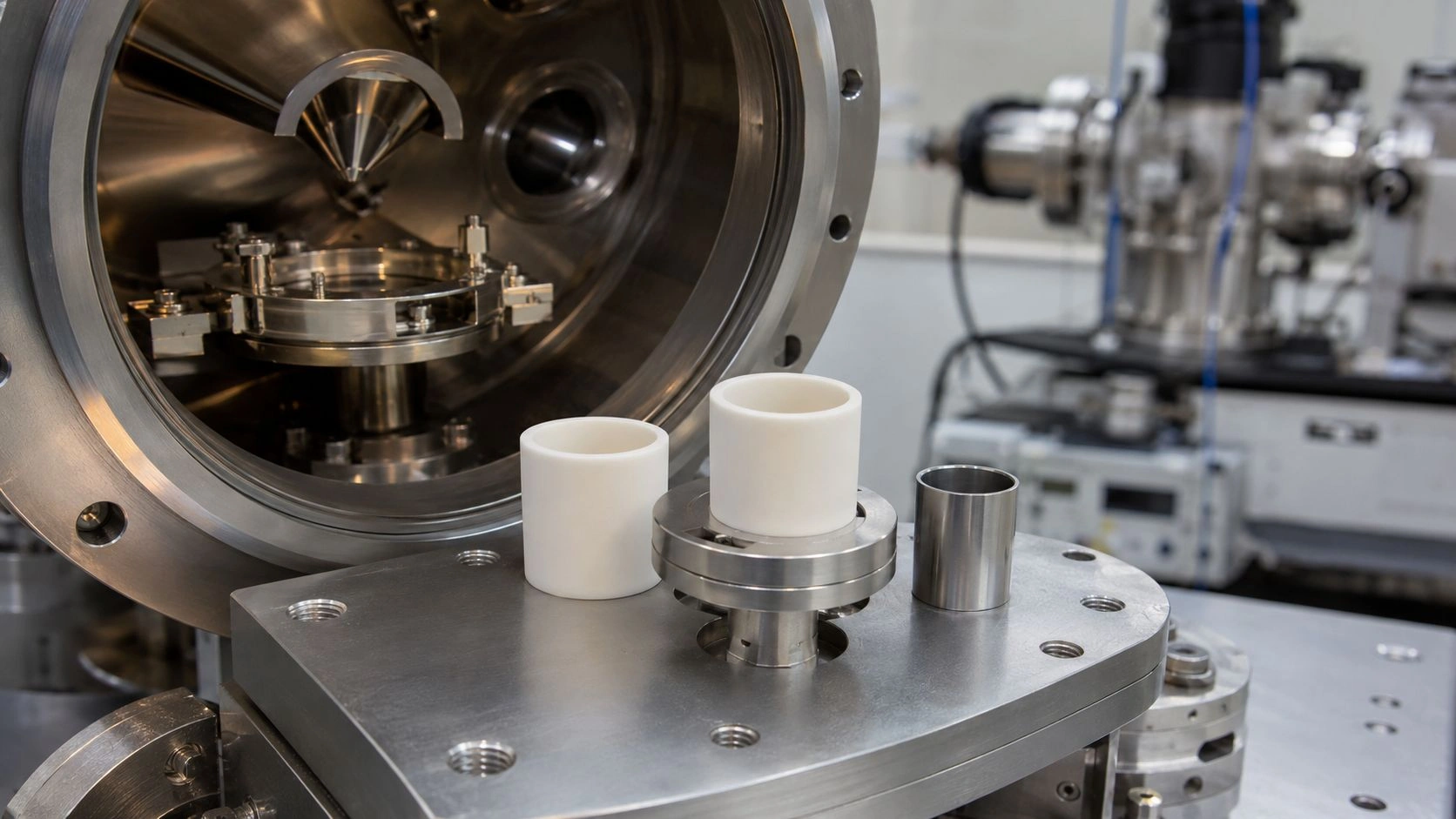
- Assembly position — how the tube sits in the holder, station, or electrode housing
- Whether the tube is glazed, unglazed, has slots, grooves, holes, or metallized bands
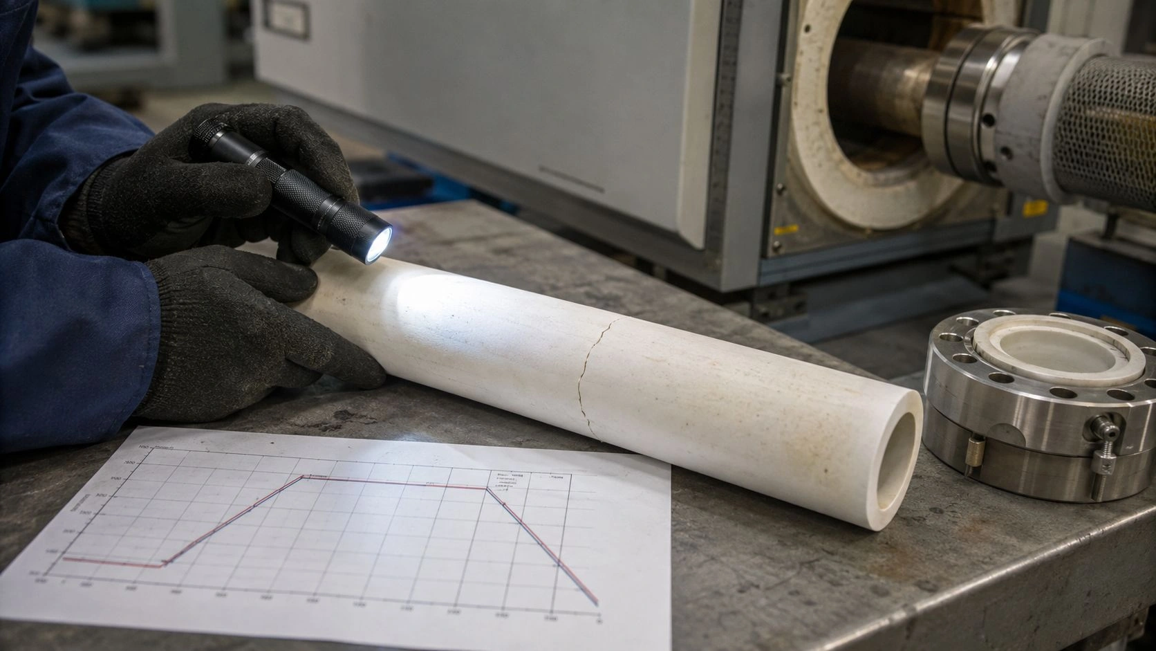
- Contamination patterns, discharge tracking marks, or fracture location
What a photo cannot reliably confirm:
- OD, ID, or wall thickness to manufacturing tolerance
- Bore concentricity or bore offset relative to the outer reference face
- End-face flatness, chamfer angle, or seating-surface perpendicularity
- Material family — alumina, steatite, mullite, and zirconia can all appear similarly off-white or ivory in photographs
- Whether a surface glaze, metallized band, or coating is present and electrically functional
A photo with a ruler or a known-size reference part beside the tube improves the preliminary review — but it should not be the final dimensional authority for a fit-critical replacement.
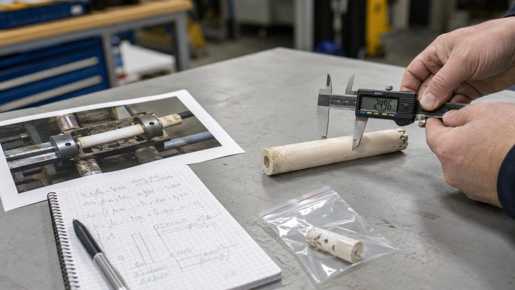
A physical sample enables direct measurement: OD, ID, wall thickness at multiple points, total length, usable straight length, end geometry, hole or slot position, and fracture-face or wear analysis. A sample also allows the supplier to review whether the ceramic body is dense, glassy, or appears porous, which informs material family and grade discussion.
Old photos help identify installation context, while a physical sample enables direct measurement of fit-critical dimensions before replacement production.
ADCERAX's custom ceramic tubes product line accepts samples, photos, and drawings as starting points for custom ceramic electrode tube manufacturing — but the RFQ process is most efficient when the input includes at least a physical sample with measured dimensions.
The first decision, then, is: what class of input is available, and what can and cannot be confirmed from it?
Which CTQ Dimensions Control Fit, Insulation, and Electrode Alignment?
Once the input quality is established, the CTQ dimensions — the measurements that determine whether the replacement actually works in the assembly — must be identified and prioritized.
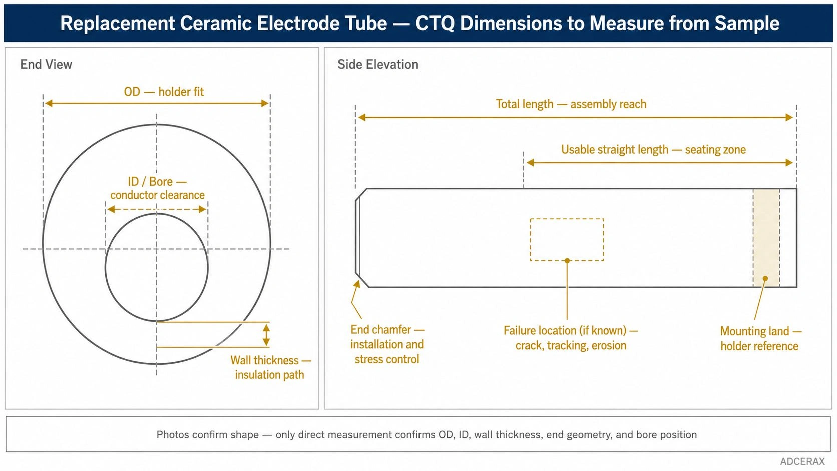
OD, ID, wall thickness, total length, usable straight length, end chamfer, mounting land, and known failure locations should be confirmed before production.
The following matrix maps each feature to its function, whether a photo can confirm it, and what evidence is needed for production.
| Feature | Why It Matters | Can a Photo Confirm It? | Better Evidence |
|---|---|---|---|
| OD | Holder fit and seating | Approximate only | Caliper measurement or drawing |
| ID / bore | Conductor clearance and alignment | Usually not | Bore gauge, pin gauge, or sample section |
| Wall thickness | Insulation path and mechanical margin | No | Direct measurement from sample |
| Total length | Assembly reach | Approximate with scale | Caliper or drawing |
| Usable straight length | Seating zone and conductor exposure | Sometimes | Sample measurement |
| End chamfer / radius | Installation and stress concentration at end | Sometimes visible | Macro photo plus measurement |
| Hole / slot position | Electrode alignment and mounting | Sometimes | CMM or recreated drawing |
| Surface glaze or metallization | Electrical tracking behavior and bonding | Sometimes visible | Supplier review plus material confirmation |
Values indicative; verify per applicable ASTM/IEC standards with supplier-specific test data.
For ceramic electrode tubes specifically, these additional operating conditions must accompany the geometric measurements in the RFQ:
- Operating temperature (continuous and peak)
- Voltage, discharge exposure, or electrical insulation requirement
- Atmosphere — air, ozone, reactive gas, vacuum, or humid environment
- Thermal cycling frequency
- Mechanical loading — clamped, simply supported, or free
Without these conditions, a supplier cannot recommend the correct material grade even if every dimension is correctly measured. ADCERAX's alumina ceramic tubes product line covers alumina grades from 96% to 99.7% Al₂O₃ with different electrical, mechanical, and temperature properties — the correct grade cannot be selected from tube geometry alone.
Why Same-Looking Ceramic Electrode Tubes Still Fail After Replacement
A replacement ceramic electrode tube can pass visual inspection, fit the holder, and still fail in service if the function of the original part was not fully understood.
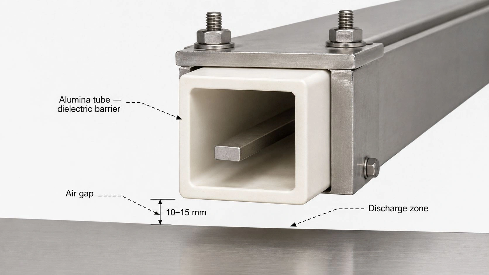
The most common replacement mistake is treating the ceramic electrode tube as a passive sleeve — a tube that just needs to fit. In many electrode assemblies, the ceramic tube also controls insulation distance between a high-voltage conductor and ground, discharge gap uniformity, thermal gradient from hot to cool zones, and mechanical seating under repeated thermal cycling. A replacement that copies the shape but misses one of these functions will fail in the same way as the original — or differently.
Geometry mismatch versus material mismatch. Alumina, steatite, mullite, and zirconia can produce tubes that look nearly identical in a photograph. They differ significantly in dielectric strength, thermal expansion, flexural strength, thermal conductivity, and maximum continuous service temperature. ASTM C1211 confirms that elevated-temperature flexural strength depends on creep, stress corrosion, or slow crack growth — factors that differ between ceramic families and that are not visible in a photograph of the failed part.
Reading failure marks on the old sample. Fracture location and pattern carry diagnostic information. A crack near the mounting end suggests bending stress at the seating interface. Electrical tracking along the surface — a discolored or carbonized line — indicates surface insulation failure, not bulk dielectric failure. Erosion at the hot tip suggests chemical or thermal attack. Chipping at a bore corner suggests tight conductor fit or assembly handling damage. Each pattern points to a different correction in the replacement specification.
Metallized features change the replacement scope. If the original tube has metallized bands — copper, nickel, or silver layers bonded to the ceramic surface for electrical connection or vacuum sealing — the replacement must either reproduce those bands or redesign the assembly without them. ADCERAX's metallized ceramic components page covers metallized alumina manufacturing for high-voltage isolation and vacuum sealing applications where material grade, metallization process, and surface compatibility must all be specified.
A surface glaze or special coating, if present on the original but absent from the replacement, can also change the electrical tracking resistance and contamination behavior.
For electrical insulation applications, IEC 60672-2 applies to ceramic and glass-ceramic materials for electrical insulation and specifies test methods — reinforcing that electrical behavior should be characterized through standardized test conditions, not inferred from visual similarity.
ADCERAX's electrical ceramics application page covers alumina, steatite, and specialty ceramic materials for high-voltage insulation and electrode tube roles where material identification and grade selection matter beyond geometry.
How to Choose the Replacement Route: Photo Review, Sample Reverse Engineering, or Drawing Recreation
The replacement route should match the functional risk of the part, not just the convenience of the available evidence.
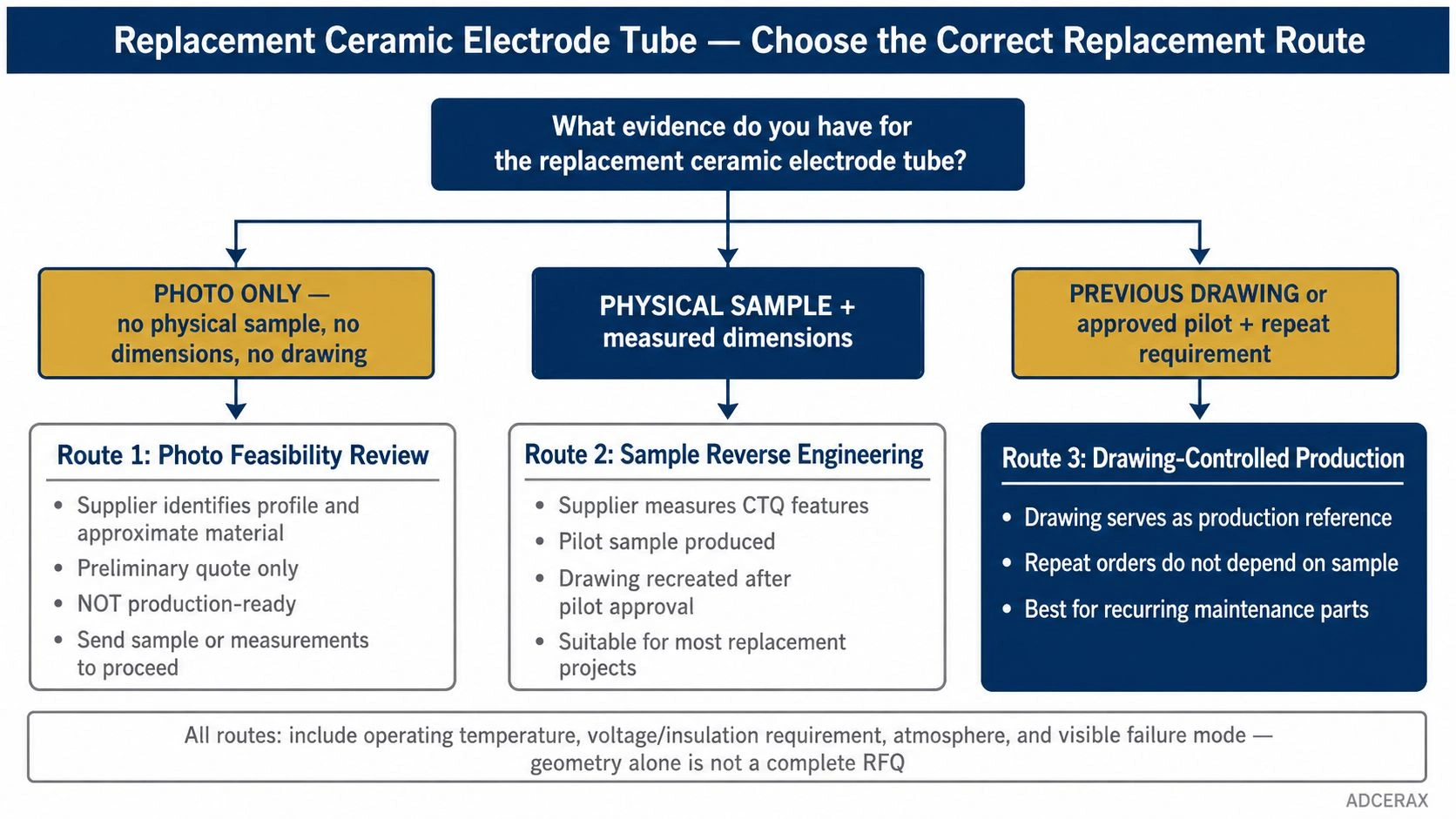
Photo review, sample reverse engineering, and drawing-controlled production represent different risk levels, so the replacement route should match the available evidence and repeat-order needs.
Route 1 — Photo review only: Appropriate for preliminary feasibility discussion, rough identification of tube profile and material family, and initial supplier communication. Not appropriate for production unless the tube is a low-risk insulating sleeve with generous tolerances and no electrical, high-temperature, or alignment-critical function.
Route 2 — Physical sample plus measured dimensions: Appropriate when the tube must fit an existing holder, conductor pin, electrode station, or burner fixture and when OD, ID, end geometry, or wall thickness cannot be safely inferred from photographs. The supplier can measure the sample, review the bore, check wall uniformity, and identify surface or material features before quoting. A pilot sample should be approved before repeat production. This route is sufficient for most industrial electrode tube and insulating sleeve replacements when a sample is available.
Route 3 — Drawing recreation: Appropriate when the part has tight datum relationships, multiple holes or slots, metallized regions, complex end geometry, or repeat-order requirements. After the first pilot sample is approved against the sample or measured sketch, the drawing is created from the confirmed dimensions and serves as the production reference. Future orders no longer depend on the old photo or worn sample.
The following matrix maps each route to its risk level and correct use case.
| Route | When to Use | What the Supplier Needs | Output |
|---|---|---|---|
| Photo review | Low-risk initial feasibility | Clear photos from multiple angles, approximate dimensions, application description | Rough quote and material family identification |
| Sample reverse engineering | Medium-risk fit-critical replacement | Physical sample, measured sketch, operating conditions, CTQ features | Pilot sample production and drawing recreation |
| Drawing recreation | High-risk or repeat-order replacement | Approved pilot sample or confirmed measured sketch | Controlled drawing for repeat production |
RFQ Checklist for Replacement Ceramic Electrode Tubes Made from Old Samples
The following checklist converts the route selection into a sendable supplier package.
Group 1 — Visual evidence:
- Photographs from at least three angles — end view, side view, and installed position
- Scale reference in at least one photograph
- Close-up photographs of end geometry, any slots, holes, grooves, or metallized bands
- Photographs of failure marks, cracks, tracking, erosion, or wear
Group 2 — Measured dimensions:
- OD (or outer square dimension)
- ID or bore diameter (or inner square dimension)
- Wall thickness at multiple positions
- Total length
- Usable straight length if different from total length
- End chamfer angle or end radius
- Hole, slot, or groove dimensions and positions if present
- Mounting land or seating surface length
Group 3 — Material and service information:
- Material family if known — alumina, steatite, mullite, zirconia, or metallized ceramic
- Operating temperature (continuous and peak)
- Voltage, discharge exposure, or electrical insulation requirement
- Gas atmosphere — air, ozone, vacuum, or reactive
- Thermal cycling frequency
- Visible damage mode — crack, tracking, erosion, or breakage
Group 4 — Procurement and verification:
- Quantity — pilot sample quantity and production quantity separately
- Target delivery or urgency
- Inspection requirements — dimensional report, material certificate, surface confirmation
- Pilot sample approval requirement before repeat production
- Request for the supplier to confirm: material grade, CTQ dimensions, tolerances, surface finish, and whether a recreated drawing is needed after sample approval
Have an old ceramic electrode tube sample or photograph? Send the photos, measured dimensions (OD, ID, length, wall thickness, and end geometry), operating temperature, electrical or discharge requirement, and how many pieces are needed. ADCERAX engineers review the sample information, confirm material grade options, and return a quote with a pilot sample plan — no commitment required at this stage.
Frequently Asked Questions
Can a ceramic electrode tube be manufactured from only an old photo?
A photo can start a feasibility review and help identify the tube profile, material family, and approximate proportions. But it is rarely sufficient for final production. The supplier still needs OD, ID, wall thickness, end geometry, and operating conditions. A calibrated photo with a ruler improves the review, but a physical sample or recreated drawing is safer for any fit-critical or insulation-critical replacement.
What should I measure before requesting a replacement ceramic electrode tube?
Measure OD, ID, total length, usable straight length, wall thickness at two or three points, end chamfer or radius, and the position of any holes, slots, or grooves. Also photograph the tube beside a scale and show how it sits in the holder or electrode assembly.
Does the replacement tube need to use the same ceramic material as the original?
Not always, but the material decision should be verified — not assumed. Similar-looking ceramics can differ in electrical insulation behavior, thermal expansion, strength, glaze character, and temperature capability. Include operating temperature, voltage or discharge exposure, atmosphere, and visible failure mode in the RFQ so the supplier can confirm the appropriate grade.
When should a drawing be recreated instead of quoting from a sample?
A drawing should be recreated when the tube has tight tolerances, metallized features, complex hole or slot patterns, multiple seating datums, or repeat-order requirements. A controlled drawing prevents future orders from depending on increasingly worn old samples.
What inspection documents should be requested for replacement ceramic electrode tubes?
Request a dimensional inspection report for CTQ features (OD, ID, wall thickness, length, end geometry), material grade confirmation, surface finish or glaze confirmation where applicable, and pilot sample approval before releasing the repeat production quantity. For high-temperature or electrical insulation service, ask which material property data or test standards the supplier can reference.