Industrial optical assemblies often fail electrically before they fail mechanically. Consequently, Black Alumina Ceramic becomes a decisive insulating material when compact geometry, high voltage, and thermal drift converge inside vision hardware.
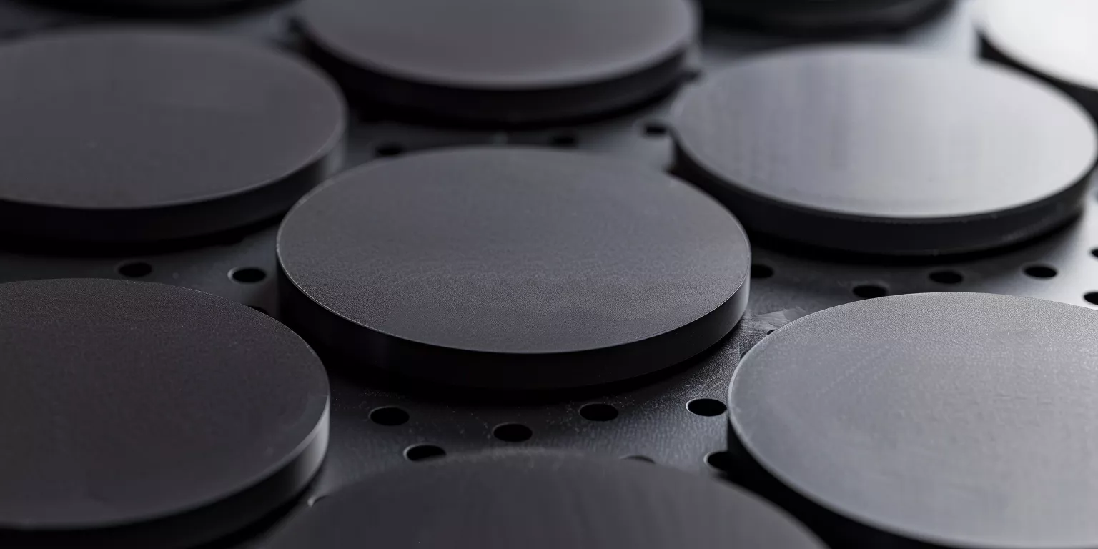
Black Alumina Ceramic is selected when designers need dense alumina behavior with a dark, low-glare surface and stable insulation. Moreover, it supports tight tolerances, repeatable interfaces, and long service life across thermal cycling and contamination-prone environments.
Accordingly, this article progresses from material fundamentals to electrical insulation demands, then to geometry control, manufacturability, reliability, and RFQ readiness. As a result, engineers and procurement teams can align specifications, inspection plans, and supplier qualification without ambiguity.
Black Alumina Ceramic must be understood as a controlled alumina system rather than a cosmetic variant. Therefore, the first step is to clarify how black coloration is achieved, which properties it perturbs, and which properties remain alumina-dominant under real optical equipment conditions.
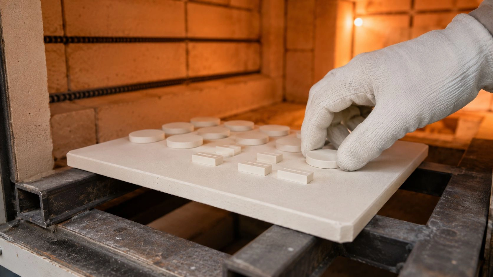
A representative component set includes insulating sleeves, spacers, mounting pads, and structural supports used near sensors, illumination drivers, and high-voltage bias circuits. Furthermore, the same part frequently sits within millimeters of optics, cabling, and grounded housings, so electrical and dimensional margins must be co-designed.
Fundamental Material Characteristics of Black Alumina Ceramic
Black Alumina Ceramic is typically evaluated as a manufacturing-grade alumina platform whose coloration signals a specific processing route. Moreover, optical and vision engineers treat it as a risk-reduction choice because it consolidates insulation, stiffness, and thermal predictability into one ceramic family.
In addition, specifying Black Alumina Ceramiccorrectly requires separating appearance from mechanism. Consequently, the material must be described through composition pathway, dielectric baseline, and thermo-mechanical envelope before any geometry or interface decisions are finalized.
Composition Pathways and Black Color Formation
Black Alumina Ceramic coloration is commonly achieved through controlled dopant chemistry and firing atmosphere rather than post-applied coatings. For instance, carbon-bearing phases or transition-metal oxides1can shift absorption while keeping alumina as the structural matrix.
During a camera head redesign I reviewed, a black ceramic sleeve was chosen after internal glare from polished metal spacers raised stray reflections in a dark-box / vision fixture screening (setup-dependent — not a factory optical SLA). Subsequently, the team learned that the color route mattered because a poorly controlled blackening process introduced a secondary glassy phase that raised leakage current during humidity exposure.
Therefore, engineers should ask for compositional intent, not only color. Typical alumina-based black ceramics remain >95–99% Al₂O₃by mass, while coloration contributors are generally kept at <1–3 wt%to avoid destabilizing grain boundaries. Notably, grain size targets for dense alumina components used in precision assemblies often fall within 2–8 μm, because excessively coarse grains elevate chipping sensitivity at edges.
In addition, the firing atmosphere can alter near-surface chemistry, which can shift surface resistivity under moisture. Accordingly, black coloration routes should be tied to repeatable sintering profiles, with documented shrinkage behavior typically in the ~15–20%linear process-order-of-magnitude teaching range from green to fired state (depending on forming method and solids loading — nota green-to-fire guarantee).
Electrical Insulation Baseline Properties
Electrical insulation is the primary procurement justification for Black Alumina Ceramic insulating parts in optical and vision modules. Consequently, baseline dielectric strength, volume resistivity, and dielectric loss must be discussed under test conditions that resemble compact opto-electronic packaging.
In one vision sensor fixture line, a ceramic spacer replaced a polymer insulator after intermittent ESD events caused image noise spikes that correlated with humidity. However, the first ceramic batch still failed because the surface finish was too rough, and contamination films formed quickly; as a result, leakage increased even though bulk resistivity was high.
Therefore, both bulk and surface metrics matter. Dense alumina ceramics commonly exhibit volume resistivity on the order of 10¹²–10¹⁴ Ω·cmat room temperature under dry conditions, while dielectric strength is application-typical / specimen-dependent (often cited in an 8–15 kV/mmscreening band) — confirm dielectric & creepage on black grade sheet + drawing; not an acceptance gate. Moreover, dielectric constant is typically around 9–10at 1 MHz, with loss tangent often in the 10⁻⁴–10⁻³band for high-quality alumina, which helps stabilize high-frequency driver circuits.
Similarly, temperature shifts these values. Consequently, resistivity may drop by 1–2 orders of magnitudeas temperature rises from 25°C to 150°C, so insulation design should rely on conservative margins and creepage management rather than assuming room-temperature behavior.
Mechanical and Thermal Stability Envelope
Optical and vision assemblies impose mechanical stability constraints because alignment drift converts directly into image blur, calibration loss, or measurement bias. Accordingly, Black Alumina Ceramic must be treated as a structural insulator with predictable stiffness and expansion rather than as a passive spacer.
In a metrology camera mount, we saw tilt repeatability degrade after a supplier changed machining parameters, producing micro-chips along the sleeve rim. Subsequently, clamp preload became inconsistent, and the sensor plane shifted by about 30–60 μmacross re-assemblies, which exceeded the system’s allowable focus stack-up.
Therefore, mechanical properties must be paired with edge integrity and finish. Dense alumina provides high stiffness, flexural strength, and hardness that are grade/specimen-dependent — confirm elastic modulus, flexural strength, and hardness on the black grade sheet (do not paste Ivory bands as Black). Moreover, alumina’s CTE is an RFQ field (often cited near 7–8 ×10⁻⁶ /K) — confirm on black grade sheet + drawing. 00°C, which supports predictable differential expansion calculations against steels and aluminum alloys used in housings.
Additionally, thermal conductivity influences local gradients. Consequently, alumina often ranges from 20–30 W/m·K for many dense grades at room temperature, while higher purity and tighter microstructure can push higher. This matters because hot spots near LED drivers or bias supplies can produce thermal gradients across an insulating sleeve, and the resulting differential expansion can translate into micrometer-level alignment drift.
Summary Parameters for Early Design Lock
| Parameter | Typical Engineering Range | Why It Matters in Optical and Vision Hardware | Verification Focus |
|---|---|---|---|
| Al₂O₃ content (wt%) | 95–99+ | Preserves alumina-dominant stiffness and insulation | Material certificate, chemistry limits |
| Grain size (μm) | 2–8 | Balances chipping resistance and strength stability | Microstructure review, edge yield |
| Linear shrinkage (%) | ~15–20 process-order teaching (not green-to-fire guarantee) | Predicts fired geometry and warpage control | Process stability, batch tracking |
| Dielectric strength (kV/mm) | Application-typical — confirm on black grade sheet | Sets thickness margin for compact insulation | Thickness-specific testing |
| Volume resistivity (Ω·cm) | 10¹²–10¹⁴ | Controls leakage under bias and humidity | Temperature/humidity conditioning |
| Dielectric constant at 1 MHz | 9–10 | Impacts high-frequency driver parasitics | Frequency-defined measurement |
| Loss tangent at 1 MHz | 10⁻⁴–10⁻³ | Reduces heating and signal distortion | Supplier data with conditions |
| Elastic modulus (GPa) | Confirm on black grade sheet | Stabilizes preload and alignment interfaces | Machining and edge integrity |
| CTE (×10⁻⁶ /K) | RFQ field — confirm CTE on black grade sheet | Predictable mismatch against metal housings | Assembly stack-up calculation |
| Thermal conductivity (W/m·K) | 20–30 | Limits hot-spot gradients in compact modules | Grade selection by heat load |
Electrical Insulation Requirements in Industrial Optical and Vision Systems
Electrical insulation is not an auxiliary requirement in industrial optical and vision systems; rather, it directly constrains reliability, signal integrity, and long-term calibration stability. Therefore, Black Alumina Ceramic is evaluated primarily against insulation performance under compact spacing, elevated bias voltage, and environmental stress that typical vision hardware experiences.
Moreover, optical and vision equipment often integrates sensing, illumination, and control electronics within confined volumes. Consequently, insulating ceramic parts must maintain electrical margins while simultaneously preserving mechanical alignment and thermal predictability, which elevates the role of ceramic insulation beyond simple dielectric separation.
High-Voltage Isolation in Imaging and Sensing Modules
High-voltage isolation appears most frequently around image sensors, photodiodes, and illumination drivers, where bias voltages commonly range from 200 V to 3 kV, depending on detector type and illumination intensity. In such assemblies, Black Alumina Ceramic sleeves and spacers are used to isolate conductive fasteners, standoffs, and mounting frames from energized components.
During a machine-vision camera upgrade project, a ceramic insulating sleeve replaced a polymer insert after repeated dielectric breakdown occurred during accelerated testing at 85°C and 85% RH. Subsequently, the alumina-based component eliminated breakdown events, even when the bias voltage was increased to accommodate a higher dynamic range sensor.
Therefore, dielectric strength alone is insufficient without geometry control. Alumina ceramics provide dielectric margin only when thickness is uniform and edges are free of micro-chipping — confirm dielectric strength on black grade sheet + drawing (application-typical / specimen-dependent; not an Ivory→Black swap or acceptance gate). In addition, cylindrical geometries reduce electric field concentration compared with sharp internal corners, which is why sleeves and bushings dominate insulation designs in optical modules.
Creepage Distance and Surface Insulation Integrity
Surface insulation integrity is often the limiting factor in compact optical assemblies rather than bulk dielectric breakdown. Consequently, creepage distance2, surface finish, and contamination susceptibility must be assessed together when specifying Black Alumina Ceramic insulating parts.
In enclosed vision systems operating near production lines, airborne oils and particulates gradually deposit onto ceramic surfaces. For instance, a flat alumina insulating plate with surface roughness above Ra 1.2 μmaccumulated conductive films more rapidly than a polished counterpart at Ra ≤0.6 μm, leading to leakage current increases of nearly one order of magnitudeafter 500 hoursof operation.
Therefore, surface preparation directly influences insulation reliability. Dense alumina ceramics typically maintain surface resistivity above 10¹¹ Ω/squnder dry conditions; however, this value can drop significantly under condensation if surface topography traps contaminants. Accordingly, specifying surface finish limits and cleaning protocols becomes as critical as selecting material grade.
Long-Term Insulation Stability Under Thermal Cycling
Thermal cycling represents a combined electrical and mechanical stress for insulating ceramics in optical systems. Indeed, frequent power cycling induces expansion mismatch between ceramic insulators and surrounding metal housings, which can create micro-gaps that attract moisture and contaminants.
In one inspection camera housing, repeated cycling between -20°C and 70°Ccaused a polymer insulator to creep, reducing creepage distance over time (validate under duty — not a relative-% guarantee). By contrast, a Black Alumina Ceramic spacer preserved electrical clearance throughout 1,000+ cycles — confirm dimensional stability on drawing + black grade sheet / duty (not a dimensional % SLA).
Consequently, alumina’s thermal stability under cycling reinforces electrical reliability. Although volume resistivity decreases with temperature, alumina ceramics demonstrate predictable behavior, enabling designers to derate voltage with confidence. In addition, stable geometry prevents unintended field concentration caused by deformation or relaxation, which is a common failure precursor in compact vision electronics.
Electrical Insulation Design Parameters Summary
| Parameter | Typical Range | Optical System Relevance | Design Control Focus |
|---|---|---|---|
| Operating voltage (V) | 200–3000 | Sensor bias and illumination drivers | Thickness and clearance |
| Dielectric strength (kV/mm) | Application-typical — confirm on black grade sheet + drawing | Prevents bulk breakdown | Uniform wall sections |
| Surface resistivity (Ω/sq) | ≥10¹¹ | Controls leakage under contamination | Surface finish, cleaning |
| Creepage distance (mm) | Confirm creepage on drawing + black grade sheet | Limits surface flashover | Geometry and layout |
| Thermal cycling range (°C) | -20 to 85 | Reflects typical vision hardware | Expansion mismatch control |
| Dimensional drift (%) | Confirm on drawing + black grade sheet / duty | Maintains clearance stability | Material and machining |
| Leakage current shift | <1 decade | Indicates insulation aging | Environmental testing |
| Relative permittivity | 9–10 | Affects high-frequency parasitics | Circuit proximity planning |
| Loss tangent | 10⁻⁴–10⁻³ | Minimizes dielectric heating | Frequency-specific data |
| Surface roughness Ra (μm) | RFQ suggestion — confirm on black grade sheet + drawing | Reduces contamination adhesion | Finish specification |
Structural Precision Demands in Optical and Vision Assemblies
Structural precision is inseparable from electrical insulation in industrial optical and vision systems. Consequently, Black Alumina Ceramic components are often tasked with holding alignment, preload, and spacing while simultaneously isolating energized elements within tightly constrained assemblies.
Moreover, optical subsystems amplify small geometric deviations into measurable performance loss. Therefore, insulating ceramic parts must be evaluated as load-bearing precision interfaces rather than passive electrical separators, especially where sensors, lenses, and illumination modules converge.
Dimensional Stability for Opto-Mechanical Alignment
Dimensional stability is the first structural requirement imposed on insulating ceramics used near optical paths. In practice, Black Alumina Ceramic sleeves, spacers, and plates frequently define the relative position between sensors and reference datums, where allowable drift is often below ±20–50 μmacross the full operating temperature range.
During a vision calibration fixture redesign, a ceramic spacer initially met drawing tolerances yet caused intermittent focus shift after thermal soak testing. Subsequent analysis showed that inconsistent wall thickness introduced asymmetric expansion, producing angular deviation of approximately 0.03°, which translated into unacceptable image distortion at working distances above 300 mm.
Therefore, geometry uniformity matters as much as nominal size. Dense alumina ceramics with controlled shrinkage profiles are typically dimensionally stable over common optical operating ranges when geometry is controlled — confirm on drawing + black grade sheet / duty (not a dimensional % SLA). In addition, their isotropic expansion behavior simplifies tolerance stack-up analysis compared with fiber-reinforced polymers, which often exhibit directional creep under sustained load.
Vibration Resistance and Mechanical Damping Behavior
Industrial vision systems are rarely static. Instead, they are mounted on robotic arms, conveyor frames, or inspection gantries that impose continuous vibration and intermittent shock. Consequently, insulating ceramic components must preserve contact integrity and preload stability under dynamic excitation.
In one automated inspection line operating at 3–5 gvibration levels, polymer insulating bushings gradually loosened, causing micro-movement between grounded housings and energized modules. By contrast, Black Alumina Ceramic bushings maintained preload consistency, and measured displacement under vibration remained below 5 μmafter 10⁷ cycles.
However, ceramics do not provide intrinsic damping. Therefore, interface design becomes critical. Alumina’s high elastic modulus (confirm on black grade sheet) ensures stiffness, yet designers often pair ceramic insulators with compliant metal washers or controlled torque limits to avoid stress concentration. In this way, vibration energy is managed at the interface rather than within the brittle ceramic body.
Interface Design Between Ceramic and Metal Components
Interfaces between Black Alumina Ceramic and metals determine whether structural precision is preserved or gradually lost. Indeed, mismatched thermal expansion, uneven preload, and sharp contact edges are frequent root causes of ceramic damage and alignment drift.
For example, when alumina sleeves are clamped directly between steel flanges without chamfer relief, localized contact stress can approach flexural allowables — confirm contact / flexural limits on the black grade sheet and set interface design accordingly. Over time, this leads to micro-cracking that is not immediately visible but degrades stiffness and insulation reliability.
Therefore, interface geometry must distribute load evenly. Recommended practices include chamfered ceramic edges, polished mating surfaces, and controlled contact lengths. Additionally, selecting metal counterparts with closer coefficients of thermal expansion, or introducing compliant interlayers, helps keep stress within safe limits as temperature fluctuates by 50–80°Cduring operation.
Structural Precision Control Summary
| Parameter | Typical Requirement | Optical System Impact | Engineering Control |
|---|---|---|---|
| Alignment drift (μm) | ≤20–50 | Image focus and calibration stability | Geometry uniformity |
| Angular deviation (°) | ≤0.05 | Field distortion risk | Wall thickness control |
| Dimensional change (%) | Confirm on drawing + black grade sheet / duty | Clearance preservation | Isotropic expansion |
| Vibration displacement (μm) | ≤5 | Signal stability | Preload management |
| Elastic modulus (GPa) | Confirm on black grade sheet | Structural stiffness | Material grade choice |
| Contact stress limit (MPa) | Confirm allowables on black grade sheet | Prevents micro-cracking | Interface design |
| Thermal swing (°C) | RFQ field — confirm duty swing + CTE on black grade sheet | Stress accumulation | CTE matching |
| Edge chipping tolerance | Minimal | Assembly repeatability | Chamfer specification |
| Surface flatness (μm) | ≤10 | Load distribution | Grinding control |
| Preload consistency | Stable | Long-term alignment | Torque definition |
Typical Black Alumina Ceramic Insulating Component Forms
Component form strongly influences how Black Alumina Ceramic performs inside industrial optical and vision systems. Therefore, understanding typical geometries helps engineers quickly map material capability to real insulation and alignment tasks within compact assemblies.
Moreover, these forms are not arbitrary. Instead, they have evolved from repeated failure analysis and assembly optimization in vision hardware, where electrical clearance, mechanical preload, and thermal behavior intersect in confined spaces.
Insulating Sleeves and Cylindrical Spacers
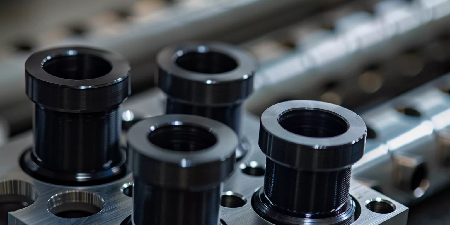
Insulating sleeves and cylindrical spacers represent the most common Black Alumina Ceramic forms used in optical and vision equipment. Typically installed around fasteners, shafts, or standoffs, they isolate energized components while preserving axial alignment and controlled preload.
In a camera head mounting assembly, replacing polymer sleeves with alumina sleeves reduced axial creep from >120 μmto less than 10 μmafter 1,000 hoursat 70°C. As a result, sensor-to-lens spacing remained within tolerance, eliminating periodic recalibration previously required during preventive maintenance.
However, sleeve performance depends heavily on concentricity and wall thickness control. Cylindrical alumina components used in precision optics often specify concentricity within ≤0.02–0.05 mmand wall thickness variation within the drawing window, because asymmetry introduces angular misalignment under thermal expansion. Therefore, grinding strategy and post-sintering inspection are critical to functional reliability.
Flat Insulating Plates and Isolation Pads
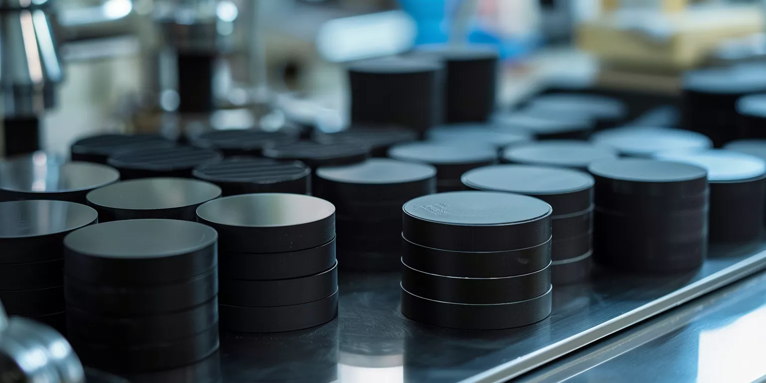
Flat insulating plates and isolation pads are widely used to separate conductive housings, PCBs, or optical subassemblies from grounded frames. In vision systems, these plates often serve dual functions as electrical barriers and thermal buffers between heat-generating electronics and sensitive optical elements.
For instance, a Black Alumina Ceramic isolation plate placed beneath an illumination driver reduced heat transfer to an adjacent sensor mount versus direct metal contact — validate under duty (not a relative-% guarantee). Consequently, thermal drift in the imaging plane dropped below 0.04 mmacross continuous operation.
Nevertheless, flatness and surface finish govern effectiveness. Plates with flatness deviation exceeding 20 μmtend to create localized contact points, raising stress and reducing effective insulation area. Accordingly, optical assemblies often put surface flatness of ≤10 μmand surface roughness of Ra 0.4–0.8 μmon the RFQ / drawing — confirm on black grade sheet + drawing to balance contact stability and contamination resistance.
Structural Insulation Supports and Mounting Elements
Structural insulation supports combine load-bearing responsibility with electrical isolation, making them particularly critical in industrial optical systems. These components frequently carry sensor modules, mirror brackets, or illumination units while preventing electrical coupling to grounded frames.
In a robotic vision gantry, Black Alumina Ceramic support posts replaced glass-filled polymer mounts that had exhibited fatigue cracking after 5 × 10⁶motion cycles. Subsequently, the ceramic supports maintained positional deviation within ±15 μm, despite exposure to vibration levels up to 4 g.
However, such components demand conservative design margins. Alumina’s high stiffness supports precision, yet its brittleness necessitates generous fillet radii and controlled mounting torque. Therefore, structural insulating elements typically incorporate chamfers or radiused transitions to keep peak stress below a conservative fraction of flexural strength confirmed on the black grade sheet, ensuring long-term stability without micro-crack initiation.
Component Form Selection Summary
| Component Form | Typical Dimensions | Primary Function | Key Engineering Control |
|---|---|---|---|
| Cylindrical sleeve | Ø10–25 mm, L 20–50 mm | Fastener and shaft isolation | Concentricity ≤0.05 mm |
| Cylindrical spacer | Ø15–30 mm, L 10–40 mm | Preload and spacing control | Wall thickness uniformity |
| Flat insulating plate | 50–120 mm, t 3–8 mm | Electrical and thermal separation | Flatness ≤10 μm |
| Isolation pad | Custom footprint | Vibration and insulation barrier | Surface finish Ra — RFQ suggestion; confirm on black grade sheet + drawing |
| Structural support post | Ø12–30 mm, L 30–80 mm | Load-bearing insulation | Stress margin control |
| Mounting block | Custom geometry | Alignment reference | Edge chamfer and fillet design |
| Spacer stack element | Modular lengths | Tolerance tuning | Batch consistency |
| Insulating washer | Ø8–30 mm | Local isolation | Edge integrity |
| Stand-off element | Thread-adjacent | Clearance preservation | Torque specification |
| Custom hybrid form | Drawing-based | Integrated functions | DFM review and inspection |
Manufacturing Control and Dimensional Consistency
Manufacturing control determines whether Black Alumina Ceramic components remain precision assets or become hidden sources of variability. Therefore, industrial optical and vision systems demand ceramics produced under tightly controlled forming, sintering, and machining regimes to ensure dimensional predictability across batches.
Moreover, these components are often procured over multi-year programs. Consequently, consistency over time matters as much as nominal tolerance, especially when optical calibration and electrical clearance depend on stable ceramic geometry.
Forming and Sintering Effects on Geometry
Forming and sintering define the baseline geometry of Black Alumina Ceramic before any precision machining occurs. In optical insulation parts, even small variations introduced during densification can propagate into alignment errors or clearance loss after assembly.
In one supplier transition audit, two alumina sleeves from different sintering batches exhibited identical green dimensions yet differed by 0.18 mmin final length after firing. Subsequently, preload variation exceeded the assembly window, forcing re-qualification of the entire vision module assembly.
Therefore, shrinkage control is critical. Dense alumina ceramics typically exhibit linear shrinkage in the ~15–20%process-order teaching range, depending on particle size distribution and forming pressure — nota green-to-fire guarantee. Moreover, uniform shrinkage is more important than absolute value; batch-to-batch shrinkage variation should be locked on the process window / PO (not a green-to-fire guarantee) to preserve machining datum consistency.
In addition, wall thickness sensitivity must be considered. Thin-walled ceramic sleeves below 3 mmthickness are more prone to ovality and warpage during sintering. Consequently, optical assemblies often favor conservative wall sections or introduce post-sinter grinding allowances to recover geometry.
Precision Machining Limits for Black Alumina Ceramic
Precision machining transforms sintered ceramic blanks into functional optical insulation components. However, alumina machining imposes limits that differ fundamentally from metals or polymers, particularly regarding edge integrity and achievable tolerance.
During a vision housing redesign, a supplier attempted to hold ±0.01 mmtolerance on a long ceramic spacer without adequate grinding support. As a result, micro-chipping drove elevated reject rates, and several accepted parts later failed vibration testing due to latent edge cracks.
Therefore, realistic machining targets must be established. For most Black Alumina Ceramic components used in optical systems, dimensional tolerances of ±0.02–0.05 mmare achievable with stable yield, while tighter tolerances require geometry simplification and increased inspection. Surface roughness values of Ra 0.4–0.8 μmare commonly specified to balance contact stability and contamination resistance.
Furthermore, edge treatment is essential. Chamfers of 0.2–0.5 mmor small fillets significantly reduce stress concentration and chipping risk. Consequently, drawings should explicitly define edge conditions rather than relying on default ceramic processing assumptions.
Batch Consistency and Statistical Quality Control
Batch consistency underpins long-term reliability in optical and vision equipment. Indeed, even when individual parts meet specification, uncontrolled variation can undermine system repeatability and calibration confidence.
In a multi-camera inspection platform, ceramic spacer length variation across three production lots caused sensor offsets of ±40 μm, exceeding the software compensation window. After introducing statistical process control on fired dimensions, variation was reduced to ±12 μm, restoring calibration stability.
Accordingly, statistical quality control should focus on critical-to-function dimensions rather than cosmetic appearance. Typical controls include Cp/Cpk ≥1.33on length and concentricity, lot-level sampling for surface finish, and periodic destructive checks for internal defects. Moreover, traceability linking raw powder batches, firing cycles, and machining runs enables faster root-cause analysis if drift appears.
Manufacturing and Consistency Control Summary
| Control Aspect | Typical Target | Optical System Impact | Verification Method |
|---|---|---|---|
| Linear shrinkage (%) | ~15–20 process-order teaching (not green-to-fire guarantee) | Predictable fired geometry | Process records |
| Shrinkage variation (%) | ≤±0.5 | Batch interchangeability | Lot comparison |
| Wall thickness (mm) | ≥3 | Warpage resistance | Design margin |
| Dimensional tolerance (mm) | Confirm on drawing + black grade sheet / duty | Alignment stability | CMM inspection |
| Surface roughness Ra (μm) | RFQ suggestion — confirm on black grade sheet + drawing | Contact and contamination control | Profilometer |
| Edge chamfer (mm) | 0.2–0.5 | Chipping reduction | Visual and tactile check |
| Concentricity (mm) | ≤0.05 | Axial alignment | CMM or roundness tester |
| Batch length variation (μm) | ≤±15 | Calibration repeatability | SPC charts |
| Process capability Cpk | ≥1.33 | Long-term consistency | Statistical review |
| Traceability coverage | Full | Rapid failure analysis | Lot documentation |
Environmental and Reliability Considerations
Environmental exposure frequently governs the real service life of Black Alumina Ceramic components in industrial optical and vision systems. Therefore, reliability must be evaluated under humidity, thermal cycling, and contamination rather than relying solely on room-condition material data.
Moreover, optical equipment often operates continuously in factory environments. Consequently, insulating ceramics are exposed to combined electrical, thermal, and mechanical stress that accumulates slowly but predictably over time.
Humidity and Surface Contamination Effects
Humidity represents one of the most underestimated reliability risks for ceramic insulating parts. Although bulk alumina retains high volume resistivity, surface conditions dominate leakage behavior when moisture and contaminants are present.
In a vision enclosure installed near a machining line, airborne coolant mist gradually condensed on ceramic isolation plates. After 600–800 hoursat 60–70% RH, surface leakage current increased by nearly one order of magnitude, despite unchanged bulk resistivity. Subsequent cleaning restored performance, confirming surface-driven degradation.
Therefore, surface finish and cleanliness are critical. Polished Black Alumina Ceramic surfaces with Ra ≤0.6 μmresist contaminant adhesion more effectively than rougher finishes. In addition, specifying cleaning compatibility with solvents or plasma treatment enables maintenance without degrading surface chemistry, which helps stabilize insulation performance over extended operation.
Thermal Shock and Repeated Power Cycling
Thermal shock and repeated power cycling impose combined stress on insulating ceramics used near illumination drivers and sensor electronics. Indeed, rapid temperature gradients can generate localized tensile stress that accelerates micro-crack initiation.
In a high-intensity lighting module cycling between standby and full power, ceramic spacers experienced temperature swings of 40–60°Cwithin minutes. Polymer alternatives deformed plastically, while Black Alumina Ceramic maintained dimensional stability after 1,500 cycles — confirm on drawing + black grade sheet / duty. However, parts with sharp internal corners developed edge micro-cracks that later propagated under vibration.
Accordingly, thermal shock resistance depends as much on geometry as material. Alumina ceramics tolerate thermal gradients when wall thickness transitions are smooth and stress concentrators are avoided. Therefore, gradual section changes and filleted internal features are preferred over abrupt geometry in thermally active zones.
Failure Modes Observed in Insulating Ceramic Parts
Observed failures in Black Alumina Ceramic insulating components are rarely catastrophic fractures. Instead, they often manifest as subtle degradation that erodes electrical or mechanical margins over time.
In reliability audits, the most common failure indicators include micro-chipping at edges, fine surface cracks near mounting interfaces, and localized discoloration associated with partial discharge. For example, partial discharge inception has been observed at electric field strengths above 2–3 kV/mmwhen surface contamination is present, even though bulk dielectric strength remains much higher.
Therefore, failure prevention focuses on early-stage risk control. Conservative electric field design, controlled surface finish, and defined inspection criteria for edge integrity significantly reduce long-term degradation. In addition, periodic environmental testing under combined voltage, temperature, and humidity provides more actionable insight than isolated single-factor tests.
Environmental Reliability Summary
| Stress Factor | Typical Exposure Range | Observed Impact | Mitigation Strategy |
|---|---|---|---|
| Relative humidity (%) | 40–85 | Surface leakage increase | Surface finish control |
| Condensation cycles | Intermittent | Creepage reduction | Cleaning compatibility |
| Thermal swing (°C) | 40–80 | Micro-crack initiation | Smooth geometry transitions |
| Power cycling (cycles) | >1,000 | Stress accumulation | Section thickness control |
| Vibration (g) | 2–5 | Crack propagation risk | Edge chamfering |
| Surface roughness Ra (μm) | >1.0 | Contaminant adhesion | Polished surfaces |
| Electric field strength (kV/mm) | 2–3 (surface) | Partial discharge onset | Field grading |
| Operating temperature (°C) | -20 to 85 | Resistivity drift | Voltage derating |
| Aging duration (hours) | >5,000 | Gradual leakage shift | Periodic testing |
| Inspection interval | Scheduled | Early failure detection | Visual and electrical checks |
Comparison With Alternative Insulating Materials
Material comparison is unavoidable during optical and vision system design reviews. Therefore, Black Alumina Ceramic is rarely selected in isolation; instead, it is evaluated against white alumina, polymer insulators, and other advanced ceramics under identical electrical and mechanical constraints.
Moreover, these comparisons are not purely material-science exercises. Rather, they reflect integration risk, long-term stability, and manufacturability within compact optical assemblies where tolerances and insulation margins are unforgiving.
Black Alumina Ceramic vs White Alumina
White alumina and black alumina share the same alumina backbone, yet they diverge in application behavior due to surface characteristics and processing history. In optical systems, white alumina is often avoided in exposed positions because light scatter and internal reflections complicate stray-light control near sensors and apertures.
In one vision module redesign, substituting white alumina spacers with black alumina equivalents cut internal reflection artifacts in low-light calibration screening — setup-dependent / not a factory optical SLA. However, electrical and mechanical properties remained comparable, with both materials remaining insulating and stiff under the same duty — confirm resistivity and modulus on the ordered black grade sheet.
Therefore, the primary distinction lies in system-level behavior rather than baseline strength. Black alumina enables optical cleanliness without sacrificing insulation, provided the black coloration route does not introduce secondary glassy phases that degrade surface resistivity under humidity.
Black Alumina Ceramic vs Polymer Insulators
Polymer insulators such as PEEK, PPS, and glass-filled nylons are frequently considered due to low cost and ease of machining. Nevertheless, in optical and vision systems operating under voltage bias and thermal cycling, polymers introduce time-dependent risks that ceramics avoid.
For instance, polymer standoffs exposed to 60–80°Csustained operation often exhibit creep exceeding 0.2–0.5%strain over 1,000 hours, which translates into tens or hundreds of micrometers of positional drift. By contrast, Black Alumina Ceramic components typically maintain dimensional change under similar conditions — confirm on drawing + black grade sheet / duty.
Additionally, polymer dielectric properties degrade with temperature and humidity. Although initial dielectric strength may be acceptable, surface tracking and contamination sensitivity increase leakage current by multiple decades over time. Consequently, polymers are best reserved for low-voltage or mechanically decoupled regions, while black alumina ceramics are favored where insulation stability and alignment must persist over years.
Black Alumina Ceramic vs Other Advanced Ceramics
Advanced ceramics such as aluminum nitride, silicon nitride, and silicon carbide also appear in optical system discussions. Each offers distinct advantages, yet none universally displace black alumina for insulating roles.
Aluminum nitride provides high thermal conductivity, often exceeding 150 W/m·K, which benefits heat spreading. However, its dielectric constant and moisture sensitivity complicate insulation design, and cost escalation limits its use to thermal-critical zones. Silicon nitride delivers exceptional fracture toughness, typically 2–3×that of alumina, yet its electrical insulation performance under high voltage is less commonly specified for compact optical assemblies.
Silicon carbide, while mechanically robust, is generally unsuitable as an electrical insulator due to its semiconductive nature. Therefore, Black Alumina Ceramic occupies a balanced position, offering predictable insulation, stiffness, and manageable cost without introducing new system-level risks.
Comparative Material Selection Summary
| Material | Electrical Insulation | Dimensional Stability | Optical Compatibility | Long-Term Reliability |
|---|---|---|---|---|
| Black alumina ceramic | Excellent | Excellent | Low reflectivity | High |
| White alumina ceramic | Excellent | Excellent | High reflectivity | High |
| Polymer insulators | Moderate | Poor to moderate | Variable | Low to moderate |
| Aluminum nitride | Good | Good | Neutral | Moderate |
| Silicon nitride | Moderate | Excellent | Neutral | High |
| Silicon carbide | Poor | Excellent | Neutral | High (non-insulating) |
| Glass-filled polymers | Moderate | Poor | Variable | Low |
| Glass ceramics | Good | Moderate | Moderate | Moderate |
| Composite laminates | Variable | Poor | Variable | Low |
| Hybrid assemblies | Dependent | Dependent | Dependent | Dependent |
Design Guidelines for Optical and Vision System Engineers
Design guidelines translate material capability into predictable system behavior. Therefore, Black Alumina Ceramic must be incorporated through geometry, mounting, and handling practices that respect both its strengths and its brittleness within industrial optical and vision assemblies.
Moreover, many field failures attributed to “ceramic weakness” originate from avoidable design oversights. Consequently, disciplined guidelines reduce risk while preserving the insulation and precision advantages that motivate ceramic selection.
Geometry and Thickness Recommendations
Geometry governs stress distribution and electrical margin simultaneously. In optical insulation parts, uniform wall thickness and gradual transitions are critical to preventing localized stress amplification under preload and thermal cycling.
In a sensor isolation sleeve application, reducing wall thickness from 4.5 mm to 3.0 mmsaved space but introduced ovality after sintering, increasing alignment drift by 25 μmunder thermal soak. After reverting to ≥3.5 mmthickness with a constant cross-section, dimensional stability improved and alignment drift fell below 10 μm.
Therefore, minimum wall thickness guidelines are essential. For most Black Alumina Ceramic sleeves and supports in optical systems, ≥3–4 mmwall thickness offers a stable compromise between compactness and geometric integrity. Additionally, internal corners should incorporate radii of ≥0.3 mm, and abrupt section changes should be avoided to limit tensile stress concentration below a conservative fraction of alumina’s flexural strength.
Mounting and Assembly Best Practices
Mounting strategy determines whether ceramic parts retain precision or fail prematurely. Indeed, uncontrolled clamping force and sharp metal edges are the most frequent causes of ceramic cracking during assembly.
In one assembly line audit, ceramic standoffs fractured intermittently despite meeting material specifications. Investigation revealed torque variation outside the process window, producing contact stress spikes above allowables confirmed on the black grade sheet. By introducing torque-controlled drivers and compliant metal washers, fracture incidence dropped to zero across 2,000+ assemblies.
Accordingly, assembly practices should limit direct metal-to-ceramic point contact. Flat, polished mating surfaces distribute load, while controlled torque values keep compressive stress within safe limits. In addition, designers should avoid bending loads on ceramic elements by ensuring load paths remain axial wherever possible.
Cleaning Handling and Packaging Considerations
Handling and cleanliness significantly influence long-term insulation reliability. Although Black Alumina Ceramic is chemically stable, surface contamination can degrade insulation performance in humid or high-voltage environments.
During a preventive maintenance cycle on a vision system, ceramic isolation pads exposed to oily residues exhibited surface leakage increases of nearly 10×compared with cleaned counterparts. After switching to lint-free handling and solvent-compatible cleaning protocols, leakage stabilized within expected limits.
Therefore, handling guidelines should specify gloves, clean packaging, and approved cleaning agents. Packaging that prevents ceramic-to-ceramic contact during transport reduces micro-chipping risk, while cleanroom-compatible handling minimizes surface contamination that could compromise creepage performance over time.
Design and Assembly Guidelines Summary
| Design Aspect | Recommended Range | System Benefit | Control Method |
|---|---|---|---|
| Minimum wall thickness (mm) | ≥3–4 | Geometry stability | Design rule |
| Internal corner radius (mm) | ≥0.3 | Stress reduction | Drawing specification |
| Section transition | Gradual | Crack prevention | CAD review |
| Assembly torque variation (%) | ≤±20 | Preload consistency | Torque tools |
| Contact stress (MPa) | Confirm allowables on black grade sheet | Structural integrity | Interface design |
| Surface finish Ra (μm) | RFQ suggestion — confirm on black grade sheet + drawing | Insulation stability | Grinding control |
| Washer compliance | Present | Stress distribution | Assembly BOM |
| Cleaning frequency | Scheduled | Leakage control | Maintenance plan |
| Handling method | Gloved | Surface protection | SOP |
| Packaging protection | Individual | Edge integrity | Shipping standard |
Optical RFQ checklist
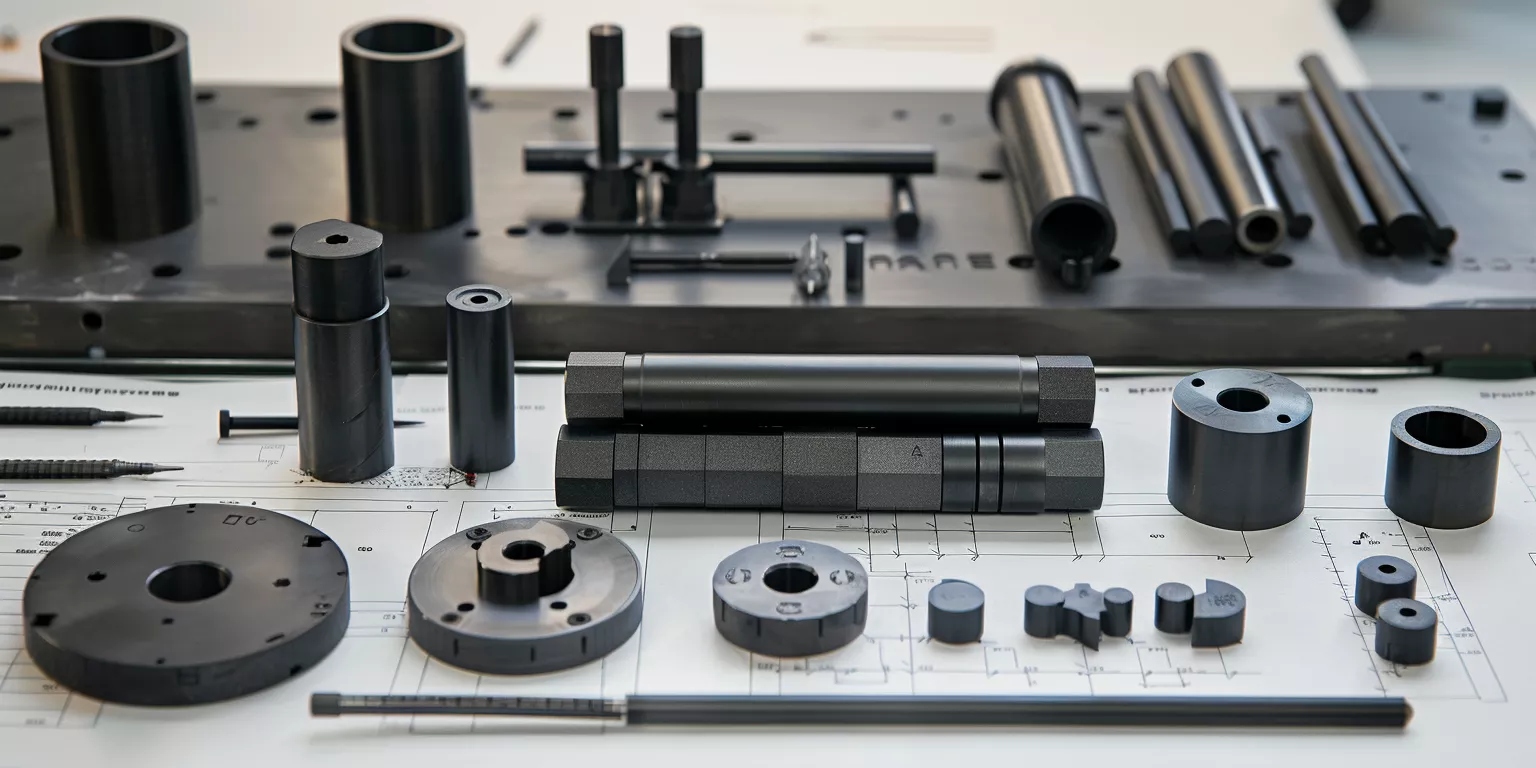
Once catalog sleeves, spacers, or plates cannot meet compact clearance, creepage, alignment, or low-reflection needs in industrial optical / vision hardware, treat the part as an engineered RFQ — not a brand catalog pick.
Use the checklist below to lock dielectric / creepage, dimensional stability, surface, and duty fields before tooling. Confirm values on the ordered black grade sheet plus the drawing; do not treat page ranges as a factory optical SLA.
RFQ fields to lock
- Electrical: bias / working voltage, humidity class, required creepage and clearance — confirm dielectric & creepage on black grade sheet + drawing.
- Geometry: critical lengths, wall thickness, concentricity / flatness, edge chamfer / fillet — confirm dimensional stability on drawing + black grade sheet / duty.
- Surface: Ra target as an RFQ suggestion (often Ra 0.4–0.8 μm for insulation-critical faces) — confirm on black grade sheet + drawing; not a surface SLA.
- Thermal / environment: thermal swing window, condensation risk, vibration — validate under duty; CTE is an RFQ field, confirm on black grade sheet.
- Process: forming route, sinter shrink process-order (~15–20% linear teaching range — nota green-to-fire guarantee), grinding datums, inspection / Cpk on key features.
- Prototype → volume:small-lot DFM validation, then lock shrinkage window and machining datums before scale-up.
For drawing-based geometry, creepage, Ra, and bias-voltage RFQ support, see custom ceramic services. Product family context: black alumina ceramic.
Optical RFQ control summary
| Capability Area | RFQ / control note | Optical System Benefit | Implementation Focus |
|---|---|---|---|
| Custom geometry | Drawing-based | Fit to compact assemblies | Early DFM review |
| Wall thickness | Confirm on drawing (≥3–4 mm typical design rule) | Stability and yield | Sintering margin |
| Dimensional tolerance | Confirm on drawing + black grade sheet / duty | Alignment repeatability | Precision grinding |
| Surface roughness Ra | RFQ suggestion — confirm on black grade sheet + drawing | Insulation reliability | Finish specification |
| Batch length variation | Agree SPC window on PO | Calibration stability | SPC control |
| Electrical suitability | Voltage-defined — confirm dielectric on black grade sheet | Clearance preservation | Material / grade selection |
| Prototype lot | Small batches | Design validation | Fast iteration |
| Volume scalability | Process lock after pilot | Program continuity | Process locking |
| Inspection strategy | Function-focused critical dims | Risk reduction | Critical dimension tracking |
| Packaging method | Individual protection | Edge integrity | Transport control |
Supplier Evaluation and RFQ Preparation
Supplier evaluation represents the final decision gate before Black Alumina Ceramic components enter industrial optical and vision systems. Therefore, engineers and procurement teams must align technical expectations, inspection strategy, and supply stability before issuing RFQs.
Moreover, optical programs often run for multiple years. Consequently, supplier capability must be judged not only on initial samples but also on repeatability, responsiveness, and long-term process control.
Critical technical information for RFQ definition
- Electrical conditions: operating voltage range, frequency, expected humidity, and duty cycle
- Mechanical constraints: load path, preload range, vibration exposure, and allowable drift
- Thermal environment: operating temperature band, cycling amplitude, and ramp rate
- Geometry sensitivity: critical dimensions, concentricity, flatness, and edge conditions
In practice, incomplete RFQs frequently lead to over-tight tolerances or under-specified inspection. For example, omitting voltage and humidity conditions can result in a ceramic grade that meets dimensional targets yet exhibits surface leakage after 500–1,000 hoursin service. Accordingly, functional requirements should always precede dimensional refinement.
Inspection and documentation alignment
Effective suppliers distinguish between cosmetic variation and function-critical deviation. Therefore, RFQs should clearly identify which dimensions require Cpk ≥1.33, which surfaces control insulation behavior, and which edge conditions must be free of micro-chipping. In addition, requesting sample inspection reports before volume commitment reduces downstream surprises.
Supply stability considerations
Finally, procurement teams should assess batch traceability, change management discipline, and communication speed. In optical systems, even small unannounced process changes can shift shrinkage behavior outside the locked process window, undermining calibration stability. Thus, supplier transparency is as valuable as technical competence.
RFQ and Supplier Evaluation Summary
| Evaluation Area | Key Requirement | Risk if Ignored | Control Method |
|---|---|---|---|
| Electrical conditions | Voltage and humidity defined | Leakage and discharge | Application data |
| Dimensional criticality | Cpk ≥1.33 on key features | Alignment drift | SPC reports |
| Surface specification | Finish and cleanliness | Creepage loss | Surface inspection |
| Edge condition | Chamfer and integrity | Micro-cracking | Visual criteria |
| Thermal profile | Cycling range specified | Stress accumulation | Design margin |
| Batch traceability | Full lot linkage | Root-cause delay | Documentation |
| Change management | Notification required | Uncontrolled drift | Supplier agreement |
| Sample validation | Pilot approval | Volume mismatch | Pre-production runs |
| Packaging method | Individual protection | Transport damage | Packaging SOP |
| Communication speed | Engineering response | Program delay | Supplier review |
Conclusion
Black Alumina Ceramic enables stable electrical insulation and structural precision when optical and vision systems demand compact geometry, predictable behavior, and long-term reliability under environmental stress.
For optical and vision engineers seeking stable insulating components, use an engineering-led RFQ (geometry · creepage · Ra · bias voltage) with controlled manufacturing and long-term supply of Black Alumina Ceramic parts — see custom ceramic servicesand black alumina ceramic.
FAQ
What makes Black Alumina Ceramic suitable for electrical insulation in optical systems?
Its high volume resistivity, stable dielectric behavior, and dimensional predictability support compact high-voltage designs near sensitive sensors.
How does surface finish affect insulation reliability?
Surface roughness influences contamination adhesion; finishes around Ra 0.4–0.8 μm(RFQ suggestion — confirm on black grade sheet + drawing) help preserve creepage performance under humidity.
Can Black Alumina Ceramic maintain alignment under thermal cycling?
Alignment can hold when geometry is properly designed — confirm dimensional stability on drawing + black grade sheet / duty (not a dimensional % SLA).
What information should be included in an RFQ for custom ceramic insulators?
Electrical conditions, thermal profile, critical dimensions, surface requirements, and inspection expectations should all be defined to avoid downstream risk.
Related reading
- Black alumina ceramic in precision mechanical systems — When contact wear / preload / mechanical fixture duty dominates instead of optical stray-light and creepage
- Black alumina ceramic for chemical processing equipment — When corrosion/chemical process media gate the black-alumina grade rather than optical bias insulation
- Alumina ceramic parts for precision positioning and measurement — When positioning/measurement fixture geometry shares the optical alignment stack but is not a dielectric design brief
References: