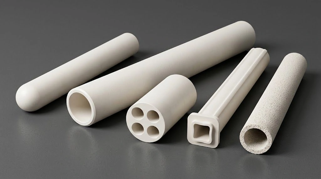
Custom diameter alumina tube selection is the foundation of accurate ceramic component design. At the beginning of every specification, defining the exact custom diameter alumina tube dimensions, tolerance class, and inspection criteria ensures functional reliability and cost efficiency. Without precise guidance, engineers risk over-specifying tolerance levels, extending lead times, and increasing cost without measurable performance benefit.
To define accurate custom diameter alumina tube requirements, engineers must align tolerance class, measurement methodology, sintering shrinkage, wall uniformity, and documentation level. This article provides a framework so each custom diameter alumina tube can be quoted and inspected against drawing-controlled OD/ID, wall, and concentricity fields — not against a generic catalog claim.

Defining Critical Dimensions: Nominal Diameter Tolerance Classes for Custom Diameter Alumina Tubes
Selecting the right tolerance class for a custom diameter alumina tube determines performance, price, and delivery time. Each class dictates the manufacturing process, achievable precision, and inspection standard. Treat the diameter bands below as typical / drawing-controlled capability by grade + forming/grind route + OD band — confirm on the drawing RFQ; they are not a universal contract SLA across all grades and sizes.
Standard tolerance class characteristics and typical applications
Standard tolerance custom diameter alumina tubes typically hold on the order of ±0.10–0.20 mm dimensional control when manufactured as-sintered (extrusion or pressing) with an as-fired surface finish often in the Ra 1.6–3.2 μm band. These tubes suit general furnace components and non-critical mechanical assemblies requiring moderate precision.
Such tolerance levels meet most industrial use cases. Circumferential variation on the order of 0.06–0.12 mm is often acceptable when no sealing or precision alignment is required. Staying in this class usually reduces cost and lead time by an order-of-magnitude step versus ground precision routes — exact deltas are RFQ-dependent.
Precision tolerance manufacturing methods and cost implications
Precision tolerance custom diameter alumina tube production typically uses OD or ID grinding after sintering to reach a drawing-controlled band on the order of ±0.05–0.08 mm, depending on grade, grind route, and OD. This route usually adds a meaningful cost and lead-time step (often cited as an order-of-magnitude uplift versus as-fired; confirm on RFQ) and improves surface finish toward a ground Ra band around 0.4–0.8 μm. These tubes are preferred for thermocouple protection, compression fittings1, and mechanical couplings requiring consistent alignment.
Grinding can improve concentricity toward an indicative capability on the order of ≤0.05 mm when referenced to an ISO 1101 geometric-tolerance framework; the drawing governs acceptance. Clear OD/ID/datum RFQ fields reduce mismatch risk between buyer and supplier evaluations.
High precision tolerance capabilities and inspection requirements
High precision custom diameter alumina tubes may deliver a drawing-controlled band on the order of ±0.02–0.03 mm with CMM-guided grinding when grade, route, and OD allow. Production cost and lead time rise further (confirm on RFQ); the resulting ground/polish Ra band around 0.2–0.4 μm supports analytical instrumentation and vacuum sealing where dimensional deviation is critical.
Full inspection maps with 8 radial × 4 axial points are a common high-precision protocol to control manufacturing stability. Over-specifying high precision grades without clear duty justification often increases cost and lead time without measurable benefit — confirm the acceptance package on the drawing RFQ.
Custom Diameter Alumina Tube Tolerance Summary
| Tolerance Class | Typical Diameter Band (mm) | Surface Finish (Ra μm) | Cost Factor (indicative) | Lead Time (weeks, indicative) | Typical Applications |
|---|---|---|---|---|---|
| Standard | ±0.10–0.20 | 1.6–3.2 (as-fired) | 1.0× | 3–4 | Furnace tubes, non-critical fit |
| Precision | ±0.05–0.08 | 0.4–0.8 (ground) | ~1.4–1.6× | 5–7 | Sealing, thermocouples, couplings |
| High Precision | ±0.02–0.03 | 0.2–0.4 (ground/polish) | ~1.9–2.3× | 8–10 | Analytical systems, vacuum assemblies |
Values indicative / drawing-controlled by grade + route + OD — not a contractual SLA. Confirm tolerance class, measurement method, and Ra + finishing route on the RFQ drawing.
Specifying Measurement Methodology: OD/ID Measurement Points and Surface Criteria for Custom Diameter Alumina Tubes
Defining clear measurement standards prevents dimensional disputes in custom diameter alumina tube procurement. Consistency across radial and axial measurement points is essential for verification.
Instrument selection and calibration requirements (ISO/IEC 17025 framework)
Measurement accuracy for custom diameter alumina tubes depends on equipment with verified calibration. Micrometers2 (typical accuracy on the order of ±0.01 mm) suit many standard grades, while CMMs3 (typical accuracy on the order of ±0.005 mm) are commonly required for precision tubes. Buyers may require calibration under an ISO/IEC 170254 framework for traceable results; that is a common inspection framework request, not an implied plant-wide certification claim for every lot. Consistent temperature at 20 ± 1 °C minimizes expansion-related errors during measurement.
Radial and axial measurement position protocols
At least four radial measurements at 90° intervals are a common baseline, while high precision tubes often use eight points for circumferential accuracy. For long tubes (>300 mm), measure every 100 mm axially is a practical protocol. The mean of all readings defines the nominal diameter, reducing interpretation variability between customer and supplier.
Clear OD/ID datum and point-count fields on the RFQ reduce dimensional mismatch risk between buyer and supplier evaluations.
Surface finish and porosity limits affecting measurement accuracy
As-fired (as-sintered) surfaces (Ra often 1.6–3.2 μm) introduce larger measurement uncertainty than ground surfaces (Ra often 0.4–0.8 μm; polish routes may reach ~0.2–0.4 μm). List Ra and finishing method (as-fired vs ground vs polish) on the RFQ — do not treat Ra as a global guarantee without a process route. Porosity targets referenced to ASTM C373 are a common buyer framework for sealing applications; confirm acceptance limits on the drawing. Visual defects deeper than ~0.3 mm are typically excluded from measurement areas.
Clear specification of surface finish method and porosity avoids supplier interpretation variance that often leads to false dimensional nonconformance.
Measurement Parameters for Custom Diameter Alumina Tubes
| Parameter | Standard | Precision | High Precision |
|---|---|---|---|
| Radial Points | 4 | 4–8 | 8 |
| Axial Points | 1/100 mm | 1/100 mm | 1/50 mm |
| Instrument Accuracy (mm, typical) | ±0.01 | ±0.005 | ±0.003 |
| Surface Ra (µm) | 1.6–3.2 (as-fired) | 0.4–0.8 (ground) | 0.2–0.4 (ground/polish) |
| Porosity (%, indicative) | <1.0 | <0.2 | <0.1 |
Instrument accuracies and Ra bands are typical / indicative — drawing and agreed method govern. Buyer may require ISO/IEC 17025-traceable calibration and ASTM C373 porosity reporting as frameworks.
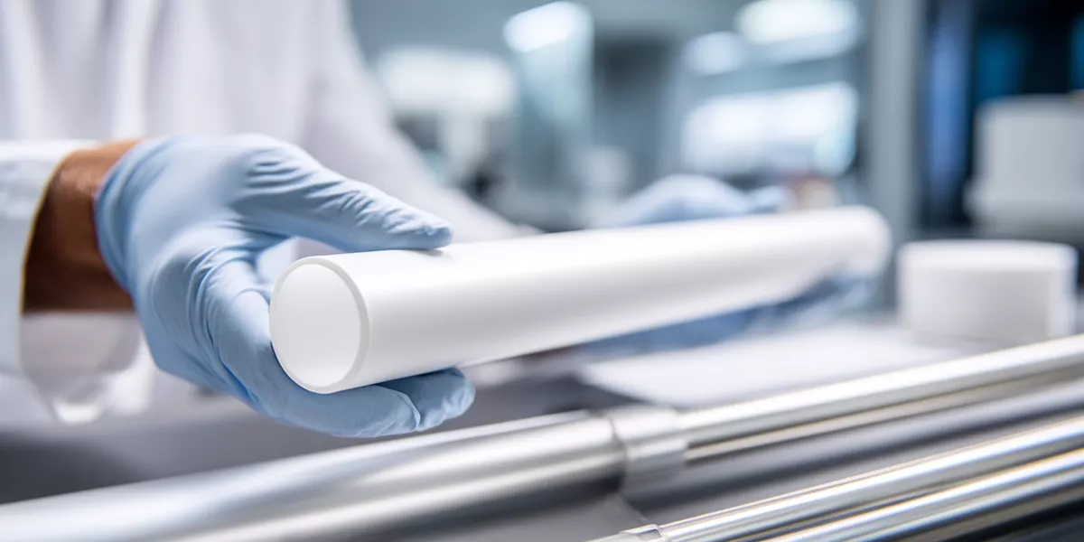
Incorporating Dimensional Stability: Accounting for Shrinkage During Sintering in Custom Diameter Alumina Tubes
Shrinkage behavior defines how close the finished custom diameter alumina tube matches target size. Compensation through validated, process-dependent data and a witness-sample protocol ensures reliable fit after firing — not a fixed percentage contract SLA.
Shrinkage factor calculation based on alumina purity and manufacturing method
Alumina ceramics typically experience a process-dependent linear shrinkage range often cited around 15–20%, with higher-purity grades tending toward the upper end of that band depending on powder, forming route, and densification. Treat any percentage as screening guidance only; variation of roughly ±0.5–1.0% commonly requires batch verification. For a 30 mm OD target, green diameter must be oversized accordingly depending on density and powder quality. Controlled sintering schedules reduce unpredictable contraction; confirm grade sheet and process route on the RFQ rather than inventing a fixed purity–shrinkage SKU pairing.
Witness sample protocols for batch-to-batch shrinkage verification
Witness samples sintered with each lot confirm dimensional consistency. They record actual shrinkage ratio versus expected and are the practical control when fixed % contracts are inappropriate — especially for larger-diameter custom tubes. Use witness-sample results to lock green compensation for subsequent lots in the same process window.
Statistical process control for shrinkage variability reduction
SPC across production runs can define control limits for a given process window. A Cpk target such as ≥ 1.33 is a common stability goal when the buyer and supplier agree a control plan. Small-diameter tubes often show tighter variation than large tubes; manufacturers with stable SPC deliver more consistent diameters across batches — confirm the control plan on RFQ rather than treating any Cpk figure as a universal guarantee.
Shrinkage Behavior in Custom Diameter Alumina Tubes
| Alumina Grade (screening) | Linear Shrinkage (%, indicative) | Variation (%, indicative) | Control Method | Accuracy (mm, indicative) |
|---|---|---|---|---|
| ~95% | 15–17 | ±1.0 | Die compensation | ±0.4–0.6 |
| ~99.5% | 17–19 | ±0.7 | SPC + Witness | ±0.3–0.4 |
| ~99.7% (higher-purity) | 18–20 | ±0.5 | CMM + Witness | ±0.2–0.3 |
Shrinkage % is process-dependent — confirm with witness samples and grade/route data. Not a fixed contractual shrinkage SLA. Grade labels are screening narrative aligned to common purity bands; do not treat as inventing a unique commercial SKU.
Mandating Wall Thickness and Concentricity Controls for Uniform Diameter in Custom Diameter Alumina Tubes
Wall uniformity directly influences thermal performance and structural life of a custom diameter alumina tube. Precise concentricity minimizes thermal stress under repeated cycles. Values below are indicative capability — drawing governs acceptance; ISO 1101 is cited as a geometric-tolerance framework.
Wall thickness coefficient of variation targets for different tolerance classes
Wall coefficient of variation (CV) targets commonly discussed are below ~8% for Standard, ~5% for Precision, and ~3% for High Precision tubes as indicative process goals. Excessive wall variation increases thermal-cycling risk; grinding can meaningfully reduce CV when the duty requires it. Confirm CV or wall min/max on the drawing RFQ rather than treating these as universal acceptance numbers.
Concentricity measurement and documentation requirements (ISO 1101 framework)
Custom diameter alumina tubes are often specified with concentricity on the order of ≤0.10 mm (Standard), ≤0.05 mm (Precision), and ≤0.03 mm (High Precision) as indicative capability under an ISO 1101 geometric-tolerance framework. Measurement at four radial positions every 100 mm is a common way to identify eccentricity caused by extrusion die wear. Documentation ensures compliance before mass production — the drawing governs.
Manufacturing process impact on wall uniformity and diameter consistency
Isostatic pressing typically achieves better wall uniformity (CV often ~3–5%) than extrusion (~6–10%). Post-sinter grinding further refines dimensional alignment. Combining these techniques can minimize TIR and support high-temperature service — confirm process route and acceptance package on RFQ (service temperatures and life-cycle claims remain application-dependent).
Wall and Concentricity Performance Summary
| Tolerance Class | Wall CV (%, indicative) | Concentricity (mm, indicative) | Manufacturing Process | Notes |
|---|---|---|---|---|
| Standard | <8 | ≤0.10 | Extrusion / as-fired | Drawing governs |
| Precision | <5 | ≤0.05 | Grinding | ISO 1101 framework cite |
| High Precision | <3 | ≤0.03 | Isostatic + CMM | Confirm on RFQ |
Wall CV and concentricity values are indicative capability · drawing governs. ISO 1101 is a geometric-tolerance framework reference, not an implied per-piece certification claim.

Documentation and Inspection Protocols: Certifying Diameter Conformance for Custom Diameter Alumina Tubes
Proper documentation confirms that each custom diameter alumina tube meets required specifications for quality and dimensional integrity.
Dimensional inspection report content and measurement data granularity requirements
Inspection reports should list OD and ID data for all agreed radial and axial points. Summarize min, max, mean, and standard deviation. Buyers may reference ASTM C1161 as a common mechanical-test framework where strength data is also required; dimensional reporting itself should follow the drawing sampling plan (e.g., ANSI Z1.4 AQL by tolerance class when agreed). Comprehensive reporting reduces dimensional claim rates versus sparse CoC-only packages.
Material certification documentation for alumina purity and physical properties
Each lot typically requires certified alumina purity, density, and open porosity aligned to the ordered grade sheet (common screening targets include purity ≥99.5% class grades, density ≥3.85 g/cm³, and open porosity <0.2% when sealing duty requires it). Confirm exact acceptance limits on the RFQ rather than treating any single purity string as a universal SKU.
Third-party inspection value for critical applications and supplier qualification
Third-party ISO/IEC 17025 accredited inspection is a path buyers may require for independent verification during supplier qualification or regulated duties. It is a common framework option — not an implied claim that every plant lot is already 17025-certified. Extra cost per lot is justified when reinspection risk is high; confirm scope on RFQ.
Inspection and Certification Framework for Custom Diameter Alumina Tubes
| Verification Level | Inspection Scope | Sampling (AQL, indicative) | Documentation | Application |
|---|---|---|---|---|
| Standard | Visual + Random | 2.5 | CoC | General furnace use |
| Precision | Statistical + FAI | 1.5 | Report + CoC | Sealing assemblies |
| High Precision | 100% + CMM Sampling | 1.0 | Cpk + CoC | Analytical use |
Conclusion
Accurate specification of a custom diameter alumina tube combines tolerance definition, process-dependent shrinkage control with witness samples, wall uniformity, and certified inspection so OD/ID acceptance is drawing-controlled. For next-step quoting, share OD/ID/length/wall, tolerance class, measurement method, Ra + finishing route, concentricity/datum, and inspection docs via the custom RFQ path — alongside the alumina tubes product page, alumina ceramic hub, and materials overview.
FAQ
1. What tolerance level suits general applications for a custom diameter alumina tube?
Standard tolerance on the order of ±0.10–0.20 mm meets most non-critical applications, balancing cost and delivery — confirm the band on the drawing by grade, route, and OD.
2. How does tolerance class affect cost and production time?
Moving from as-fired Standard to ground Precision or High Precision usually adds an order-of-magnitude cost and lead-time step; exact percentages are RFQ-dependent. Over-specifying without duty benefit is the common cost trap.
3. What documents should accompany a custom diameter alumina tube order?
Each order should include dimensional reports, material certificates, and process traceability records. For critical use, buyers may require third-party inspection under a common ISO/IEC 17025 framework.
4. How do custom diameter alumina tubes compare to standard catalog sizes?
If dimensional deviation from a catalog size is within a small allowance and duty allows, a standard size may meet performance needs at lower cost and faster lead time — confirm fit and tolerance class on RFQ rather than assuming custom is always required.
Related reading
- Precision grinding processes for ground alumina tubes — When the bottleneck is precision grinding process choice for ground alumina tubes — not OD/ID tolerance-class selection on the RFQ
- Critical factors for precision-length alumina tubes — When the buyer must lock precision length / cut-length stack-up, not diameter class
- Wall thickness for alumina tubes in fluid transport — When the duty is fluid-transport wall thickness vs pressure, not custom diameter tolerance/inspection (≠ SiC slurry abrasion liner)
References:
-
Compression fittings create a mechanical seal on tube OD — relevant when precision OD tolerance and surface finish must support leak-tight joints. ↩
-
Micrometers are a common handheld method for tube OD/ID checks; typical accuracy on the order of ±0.01 mm suits many standard grades when calibrated. ↩
-
CMMs provide multi-point OD/ID and geometric checks for precision tubes; typical accuracy on the order of ±0.005 mm when the method is agreed on the RFQ. ↩
-
ISO/IEC 17025 is a common buyer framework for calibration and testing laboratories; buyers may require traceable calibration under this framework — it is not an implied plant-certification claim for every lot. ↩