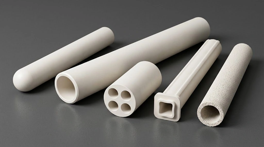
Insulation reliability in electrical systems operating near 1500°C depends on whether the ceramic wall stays an insulator or transitions toward conduction under voltage stress. At those conditions, purity, grain structure, and density of the alumina tube wall become the levers that keep resistivity high enough to prevent breakdown events.
Engineers specify high-temperature alumina insulation tubes to balance electrical isolation, mechanical strength, and thermal stability. Required dielectric performance is geometry- and waveform-dependent — a coupon breakdown field is not a finished-part working-voltage rating (state thickness, waveform, electrodes, and medium). Insulation-tube geometries for size, bore, and custom RFQ should be confirmed against the ordered grade data sheet and duty. This guide explains how temperature, material quality, and structural design affect insulation behavior so RFQ specs stay aligned with service conditions.

What Is Dielectric Strength and Why Does It Define High Voltage Alumina Tube Performance at Extreme Temperatures?
For insulation-tube applications above 1200°C, dielectric strength is the maximum electric field intensity (kV/mm per an agreed method such as ASTM D149 or IEC 60243, with specimen thickness stated) the ceramic resists before electron release creates conductive channels. Electrical breakdown occurs when local field stress exceeds that limit for the tested geometry and waveform — confirm the applicable value and specimen conditions on the ordered grade data sheet rather than treating a generic industrial threshold as a contract number.
High-purity alumina tubes (≥ 99.5% Al₂O₃) are typically preferred when high-temperature insulation resistance matters, because lower-purity grades carry more silicate grain-boundary phases that can increase leakage as temperature rises. Above 1500°C, ionic conduction accelerates; specify the required breakdown method, wall thickness, waveform, and design margin on the drawing, and confirm high-temperature resistivity by an agreed method (temperature, voltage, dwell, electrodes, atmosphere). Verified batch certification is essential when service voltages are high or when insulation failure may damage equipment.
ADCERAX alumina grades list typical dielectric strength 10 kV/mm on a 5 mm specimen. That coupon result is not a finished-tube working-voltage rating — specify wall thickness, waveform (AC/DC/impulse), electrodes, medium, temperature, and design margin; confirm on the ordered grade data sheet and duty.
Defining dielectric breakdown voltage versus dielectric strength in high voltage alumina tube
Dielectric strength is an intrinsic limit reported per material thickness under stated electrodes and medium, whereas breakdown voltage depends on geometry. Using E = V/t, a 3 mm wall at a given average field stress supports a proportional voltage before the average field reaches the coupon limit — but micro-defects, edges, and electrode geometry can still trigger premature discharge. Correct distinction between coupon field and part working voltage avoids false safety margins.
Electric field concentration mechanisms at grain boundaries and surface defects
Grain boundaries act as stress amplifiers under high electric fields. Surface scratches and pores can intensify electric stress several times locally, initiating flashover. Polishing insulation-tube surfaces to a fine Ra (commonly targeted below about 0.8 µm when drawings require it) reduces field peaks and improves dielectric endurance during thermal cycling — confirm finish method and acceptance on the drawing.
Critical threshold values separating insulator from conductor behavior at 1500°C
At 1500°C, the insulating state can collapse once leakage current density rises under the applied field. Maintaining adequate dielectric margin for the actual wall, waveform, and temperature ensures the tube continues as a true electrical insulator during furnace or plasma operation. Confirm high-temperature insulation behavior on the ordered grade data sheet and duty rather than assuming a room-temperature coupon field applies unchanged.
How Does 1500°C Temperature Affect Dielectric Strength Degradation Mechanisms in High Voltage Alumina Tube?
Dielectric margin of alumina insulation tubes declines with temperature due to Arrhenius-controlled ionic conduction. Volume resistivity is high at room temperature on grade sheets (typically >10¹⁴ Ω·cm at 20°C for high-purity grades); high-temperature resistivity must be confirmed by an agreed method (temperature, voltage, dwell, electrodes, atmosphere) — there is no universal 1500°C breakdown or resistivity contract curve on the standard alumina grade sheet. Engineers should apply a design safety factor matched to duty (often in the 1.5–2.0× range for continuous high-temperature service) and state the factor on the drawing.
Arrhenius temperature dependence of ionic conductivity
Activation energy on the order of ~1.2 eV allows Na⁺ and Ca²⁺ ions to migrate once above roughly 1200°C, decreasing resistivity. Limiting alkali and related impurities helps prevent excessive conduction. High-purity compositions maintain more consistent dielectric behavior despite thermal excitation — confirm chemistry limits on the ordered grade data sheet.
Grain boundary phase transitions creating conductive pathways
Near ~1400°C, silicate grain-boundary phases can soften and form thin conductive films. This mechanism explains why 95–99% grades often show faster insulation loss than cleaner grades. Targeting purity ≥ 99.5% for high-temperature electrode or insulation duty mitigates low-melting eutectics when the duty requires it — purity alone does not automatically set dielectric strength.
Electronic contribution to conductivity from thermal carrier generation
Thermal excitation across alumina’s wide bandgap (~8.8 eV) can generate electron-hole pairs, adding slight conduction. Stable crystal lattice and low defect concentration suppress this effect, retaining insulation capability at high field strength.
Quantifying breakdown field reduction from 25°C to 1500°C
| Temperature (°C) | Breakdown Strength (kV/mm) | Volume Resistivity (Ω·cm) |
|---|---|---|
| 25 | Confirm on grade sheet (specimen thickness, method) | Confirm @ stated T (typically high at ~20°C on grade sheet) |
| 800 | Confirm by agreed HT method — trend: margin declines vs RT | Confirm by agreed method (T, V, dwell, electrodes, atmosphere) |
| 1200 | Confirm by agreed HT method — further margin decline expected | Confirm by agreed method (T, V, dwell, electrodes, atmosphere) |
| 1500 | Confirm by agreed HT method — do not use RT coupon as working rating | Confirm by agreed method (T, V, dwell, electrodes, atmosphere) |
The qualitative trend is that dielectric margin falls as temperature rises; reliable isolation at 1500°C still requires correct grade selection, geometry, and verified high-temperature test conditions — not an assumed absolute kV/mm curve.
Which Material Properties Enable High Voltage Alumina Tube to Maintain Dielectric Strength at 1500°C?
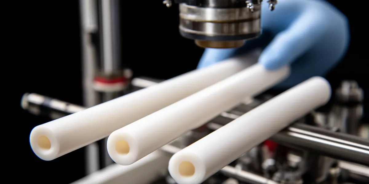
Three core levers—high relative density, controlled grain size (often targeted in a fine-to-medium band such as ~5–8 µm when process windows allow), and purity suited to the duty (commonly > 99.5% Al₂O₃ for high-temperature insulation)—drive dielectric performance. Raising densification and reducing interconnected porosity typically improves high-temperature insulation resistance; confirm density, porosity, and resistivity targets on the ordered grade data sheet rather than treating any published 10× resistivity jump as a factory guarantee.
Density requirements eliminating interconnected porosity networks
Open porosity creates potential conductive and moisture paths. Reducing open porosity toward dense sintered levels improves dielectric reliability. Insulation tubes sintered in an appropriate high-temperature densification window achieve the microstructural integrity critical to insulation durability — confirm density/porosity acceptance on the grade sheet and drawing.
Grain size effects on boundary area and conduction path density
Fine grains increase boundary area, while coarse grains can lower mechanical strength. An intermediate grain-size distribution minimizes conduction-path density without weakening structure. Consistent grain morphology supports more uniform voltage distribution.
Phase purity preventing eutectic liquid formation
Impurities that form low-melting glass phases weaken electrical barriers. Keeping silica and alkali oxides low prevents conductive eutectic formation. Certified chemistry (for example ICP-MS where specified) verifies compliance for insulation-critical batches.
Alpha-alumina stability across the operational temperature range
Stable α-phase alumina avoids transformation-induced microcracking. XRD or equivalent phase checks confirm structural stability through the planned temperature window. Stable corundum phase supports dielectric integrity during repeated heating cycles.
What Minimum Dielectric Strength Specifications Ensure High Voltage Alumina Tube Withstands 1500°C Operation?
Do not treat any single absolute kV/mm figure as a universal “standard requires” value at 1500°C. For a given voltage and wall thickness, compute average field stress E = V/t, then state the required breakdown test method, specimen or part geometry, temperature, and design margin on the drawing. Confirm dielectric strength on the ordered grade data sheet — typical coupon listing is 10 kV/mm on a 5 mm specimen, which is not a finished-tube working-voltage rating. For electrode-tube RFQ field lists (dimensions, waveform, duty), see ceramic electrode tube RFQ information.
Calculating required breakdown strength from geometry and voltage
Electric field E = V/t. For a 9 kV system with a 3 mm wall, E = 3 kV/mm average. Select wall thickness and grade so the average field stays well below the verified breakdown capability for the stated method and temperature, with an explicit safety factor on the drawing.
Safety factor determination for critical service environments
Aerospace systems often require ≥ 2.0× safety factor; industrial furnaces commonly apply about 1.5×. This margin accounts for aging, contamination, and temperature fluctuations during long continuous operation — state the factor and duty hours on the RFQ.
Withstand voltage testing validating tube integrity
| Test Type | Condition | Duration (s) | Pass Criterion |
|---|---|---|---|
| AC Voltage | Agree multiplier × rated (e.g. 1.5× when specified) | Agree (often 60) | No breakdown/corona — confirm on PO / drawing |
| DC Voltage | Agree multiplier × rated (e.g. 2× when specified) | Agree (often 30) | Leakage limit per drawing (method-dependent) |
| Impulse | Agree transient multiple | Agree pulse count | No flashover — confirm waveform & electrodes |
Insulation tubes that pass the agreed AC/DC/impulse suite under stated electrodes and medium support robust service — pass criteria belong on the purchase specification, not as implied factory defaults.
Temperature-compensated specification to offset degradation
Room-temperature coupon dielectric strength does not automatically equal high-temperature capability. Specifications must reflect operating temperature, waveform, and geometry — not ambient coupon data alone — to avoid overrating materials in high-temperature systems.
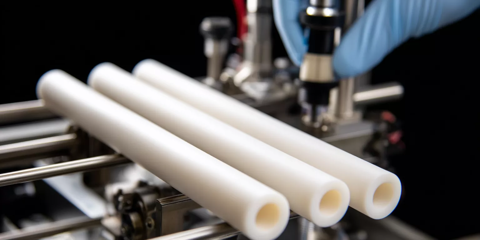
What Design and Manufacturing Strategies Guarantee High Voltage Alumina Tube Dielectric Integrity at 1500°C?
Precision manufacturing supports electrical reliability. Wall thickness is chosen so average field stress stays a defined fraction of verified breakdown capability. Surface finish (often Ra < 0.8 µm when specified) and controlled sintering to high relative density reduce localized discharge risk. Chemistry checks verify alkali and alkaline-earth limits when insulation-critical. Controlled cooling can introduce beneficial surface compression; treat any stated MPa or percent dielectric uplift as process-discussion guidance to validate on the part, not as an unconditional factory guarantee.
Wall thickness optimization balancing field stress and thermal shock
Thicker sections lower electric stress yet can limit thermal-shock tolerance. A mid-range wall (for example around 3 mm in many HV insulation layouts) often balances both at moderate service voltages — confirm for the actual voltage and ramp. Dimensional tolerance (commonly ± 0.1 mm when drawings require it) prevents localized overstress zones.
Surface finish improving field uniformity
Microscopic roughness concentrates fields. Polishing insulation-tube surfaces to the agreed Ra reduces amplification and improves endurance across repeated thermal cycles.
Sintering control achieving full density
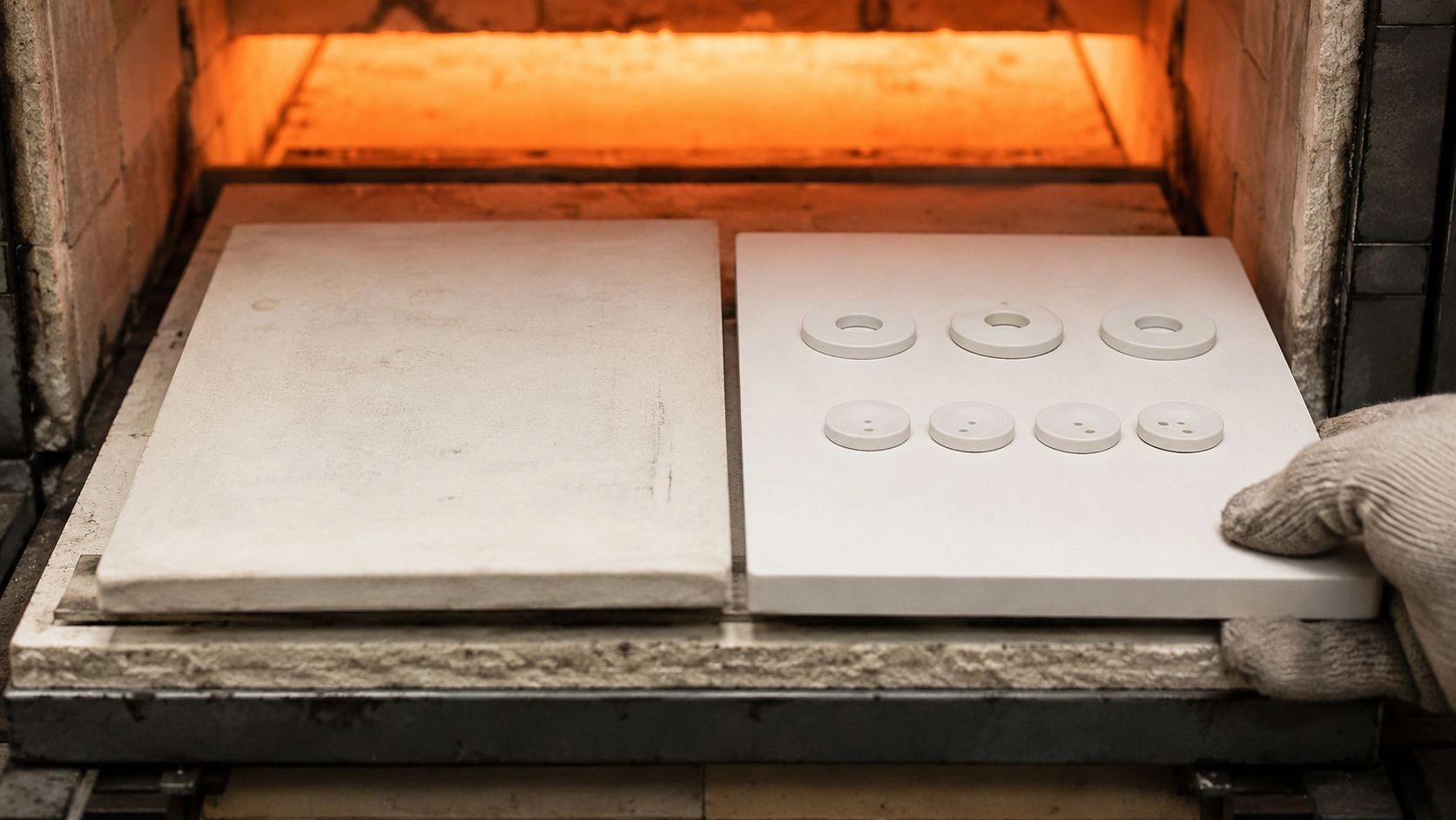
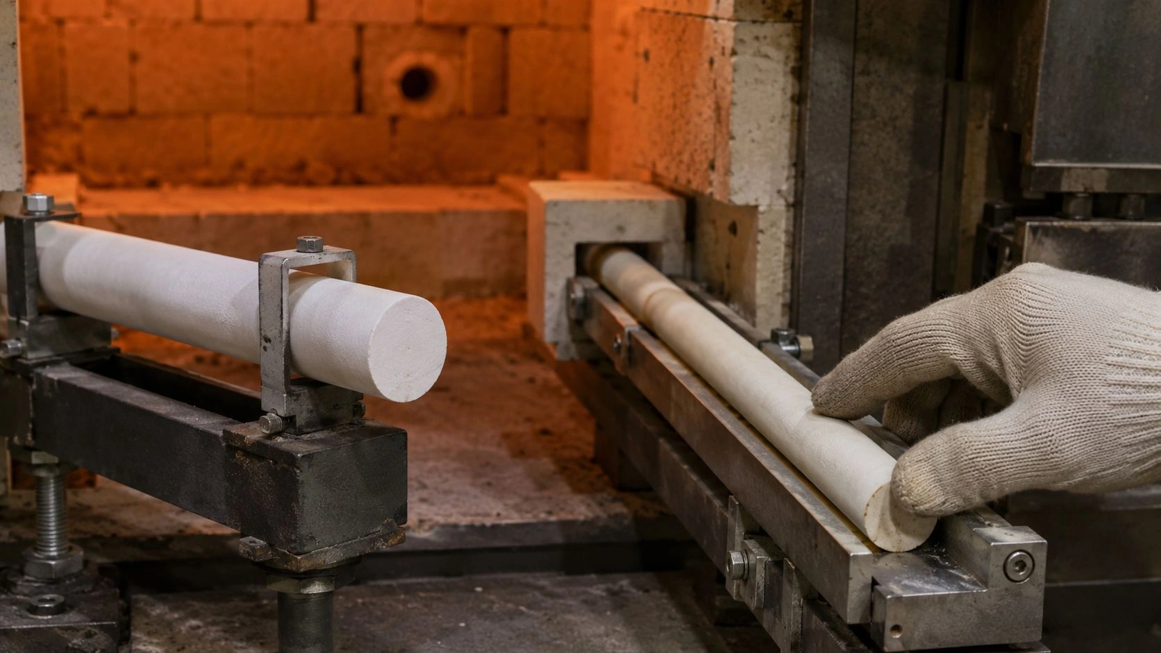
A controlled high-temperature hold secures high relative density while retaining a fine-to-medium grain size. Preventing grain coarsening safeguards dielectric uniformity and structural integrity — confirm process window with the manufacturer for the ordered grade.
Post-manufacturing quality validation through high-potential testing
Each insulation-critical batch should undergo agreed hipot / withstand testing (multiplier × rated, dwell, electrodes). Acceptable leakage and no-breakdown criteria belong on the drawing. Certified data should accompany shipments when the RFQ requires it.
Expert Insight: Balancing Wall Thickness and Thermal Shock Constraints
Electrical failures in high-temperature insulation tubes often originate not from bulk dielectric deficiency but from microcracks induced by thermal shock. Fine cracks can allow moisture intrusion and ionic conduction during cooling. Controlled cooling that builds a compressive surface layer can improve both dielectric endurance and thermal-shock resistance — validate the cooling schedule and wall thickness on the actual geometry. This can allow thinner walls in rapid-response heating systems when thermal-shock qualification passes, without treating any fixed wall reduction or percent uplift as a universal guarantee.
High Voltage Alumina Tube Dielectric Performance by Purity Grade at 1500°C
| Purity Grade | Dielectric Strength (kV/mm) | Resistivity (Ω·cm) | Density (g/cm³) | Max Operating Voltage (kV, 3 mm wall) |
|---|---|---|---|---|
| 95% Al₂O₃ | Confirm on grade sheet — typical coupon listing is 10 kV/mm @ 5 mm specimen (not purity-scaled) | Confirm @20°C on grade sheet; HT by agreed method | Confirm on grade sheet | Not a grade-sheet working rating — derive from E=V/t + margin + HT verification |
| 99% Al₂O₃ | Confirm on grade sheet — same coupon basis as other dense alumina grades unless sheet states otherwise | Confirm @20°C on grade sheet; HT by agreed method | Confirm on grade sheet | Derive from geometry, waveform, temperature, and design margin |
| 99.5% Al₂O₃ | Confirm on grade sheet — purity does not automatically raise coupon dielectric above the sheet listing | Confirm @20°C on grade sheet; HT by agreed method | Confirm on grade sheet | Derive from geometry, waveform, temperature, and design margin |
| 99.8% Al₂O₃ | Confirm on grade sheet — do not assume a stepped kV/mm ladder by purity | Confirm @20°C on grade sheet; HT by agreed method | Confirm on grade sheet | Derive from geometry, waveform, temperature, and design margin |
Selection note: grade-sheet dielectric strength is typically listed on a fixed specimen basis (e.g. 10 kV/mm on a 5 mm specimen across dense alumina grades). Purity mainly affects high-temperature insulation chemistry and secondary phases — it does not automatically set finished-part working voltage.
High Voltage Alumina Tube Specification Decision Matrix for 1500°C Applications
| Operating Condition | Specification Requirement |
|---|---|
| > 10 kV & continuous 1500°C service | State required purity/grade, breakdown method, specimen/part geometry, temperature, and design margin on the drawing; confirm on ordered grade data sheet & duty |
| > 2× transient voltage & > 50 cycles/day | Controlled cooling + stated safety factor (often ~2.0×) — validate thermal-shock and dielectric together |
| Wall < 2 mm & > 5 kV operation | Reject thin wall for that voltage unless E=V/t + HT verification + margin are explicitly qualified; often specify ≥ 2.5 mm wall as a starting RFQ gate |
| Aerospace or medical systems | Prototype / lot testing to the agreed method (e.g. IEEE 98 or equivalent) at the stated multiplier × rated voltage |
Conclusion
High-temperature alumina insulation tubes provide robust electrical isolation near 1500°C when material purity, density, geometry, and verified test methods are specified together. Treat coupon dielectric listings as specimen data, separate finished-part working voltage from coupon field strength, and close the RFQ with waveform, wall, temperature program, and acceptance method filled in.
Writing a dielectric RFQ for a high-temperature alumina insulation or electrode tube? Send voltage waveform (AC/DC/impulse), wall thickness and bore, temperature program, required breakdown/hipot method, and electrode/medium conditions for a neutral dielectric RFQ checklist review against the ordered grade data sheet and duty — no catalog commitment required at this stage.
FAQ
Q1: How does purity affect high voltage alumina tube dielectric performance?
Higher purity reduces conductive silicate phases and generally improves high-temperature insulation behavior versus lower-purity grades. Coupon dielectric strength on the grade sheet is typically listed on a fixed specimen basis (e.g. 10 kV/mm on a 5 mm specimen) and is not an automatic purity-scaled ladder — confirm chemistry and electrical values on the ordered grade data sheet.
Q2: What safety factor applies for 1500°C insulation design?
Use about 1.5–2.0× depending on thermal cycling and voltage spikes, and state the factor on the drawing to support long-term reliability.
Q3: How is dielectric certification verified for procurement?
Request agreed-method reports (e.g. ASTM D149 / IEC 60243 and any IEEE 98 or hipot suite named on the PO) with actual breakdown or withstand results for each production batch, including specimen thickness and electrodes.
Q4: How does alumina compare with zirconia for high voltage service?
Alumina generally offers stronger dielectric insulation and lower high-temperature conductivity for insulation-tube duty, while zirconia offers greater toughness but weaker insulation behavior at very high temperature — confirm both families on their respective grade sheets for the planned waveform and temperature; do not rely on a single absolute kV/mm comparison figure.
Related reading
- Custom ceramic electrode tube RFQ information — what dimensions, voltage waveform, and duty data belong on a ceramic electrode tube RFQ.
- Alumina purity options for ceramic electrode tubes — when electrode-tube insulation duty needs a cleaner alumina grade versus a standard furnace tube grade.
- Square alumina tube corona electrode specification — how square alumina tubes are specified for corona electrode service and dielectric checks.