A risk-control and specification guide for equipment engineers and process engineers — covering why long square alumina ceramic electrode tubes are more sensitive to bow, twist, and handling damage than short sections, which failure modes require inspection, how functional straightness differs from visual straightness, what to specify in the drawing and RFQ, and how to manage handling, packing, and pilot approval.
Long square alumina ceramic electrode tubes carry higher straightness and handling risk because length magnifies bow, twist, edge chipping, and unsupported-span damage. Square cross-sections help orientation and holder fit, but their corners and long flat faces require clear straightness, twist, wall-thickness, edge-condition, packing, and inspection requirements. The safest specification treats the tube as both an electrical insulator and a brittle structural component: define the operating role, support points, active electrode alignment, and pilot-sample approval before repeat production.
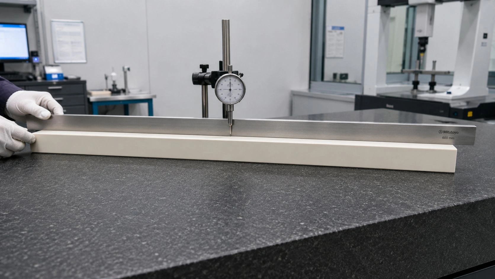
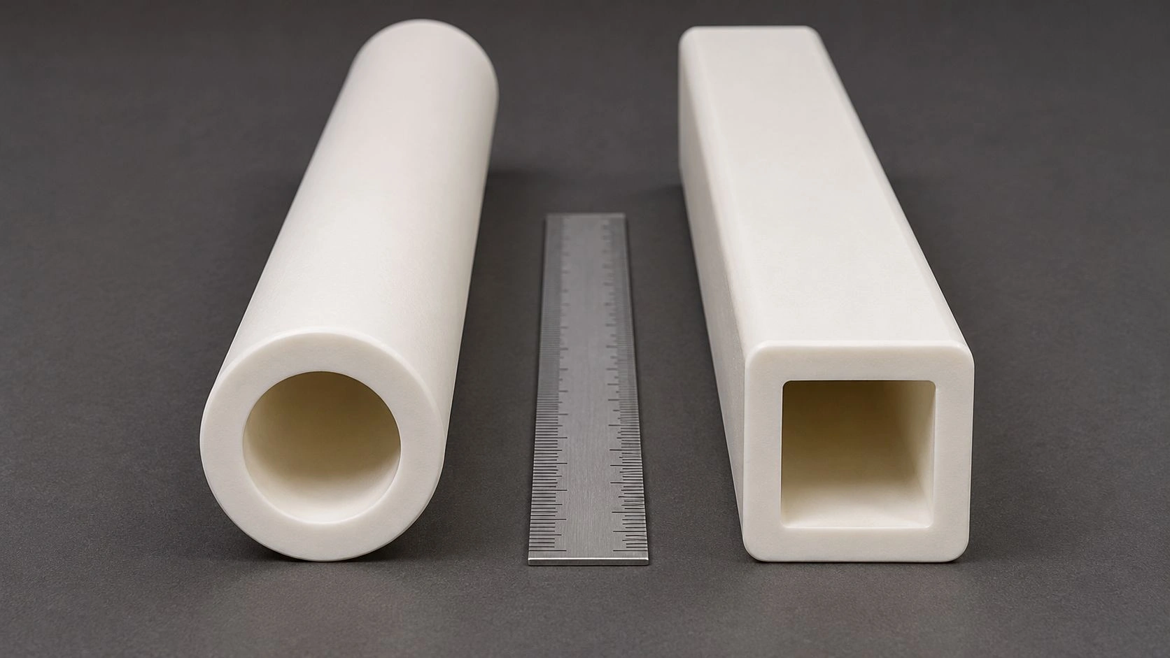
For long square alumina electrode tubes, functional straightness should be checked against a defined reference face rather than judged by visual appearance alone.
Why Long Square Alumina Electrode Tubes Magnify Straightness Risk
A long square alumina ceramic electrode tube is not simply a longer insulating sleeve. Length multiplies the effect of small bow and twist because the tube must maintain alignment over a much larger unsupported span than a short section of the same cross-section. A bow of 0.3 mm over 80 mm length may have no consequence in a loose sleeve holder. The same absolute bow over 600 mm can prevent insertion, cause uneven clamping, or shift the electrode path relative to the discharge gap.
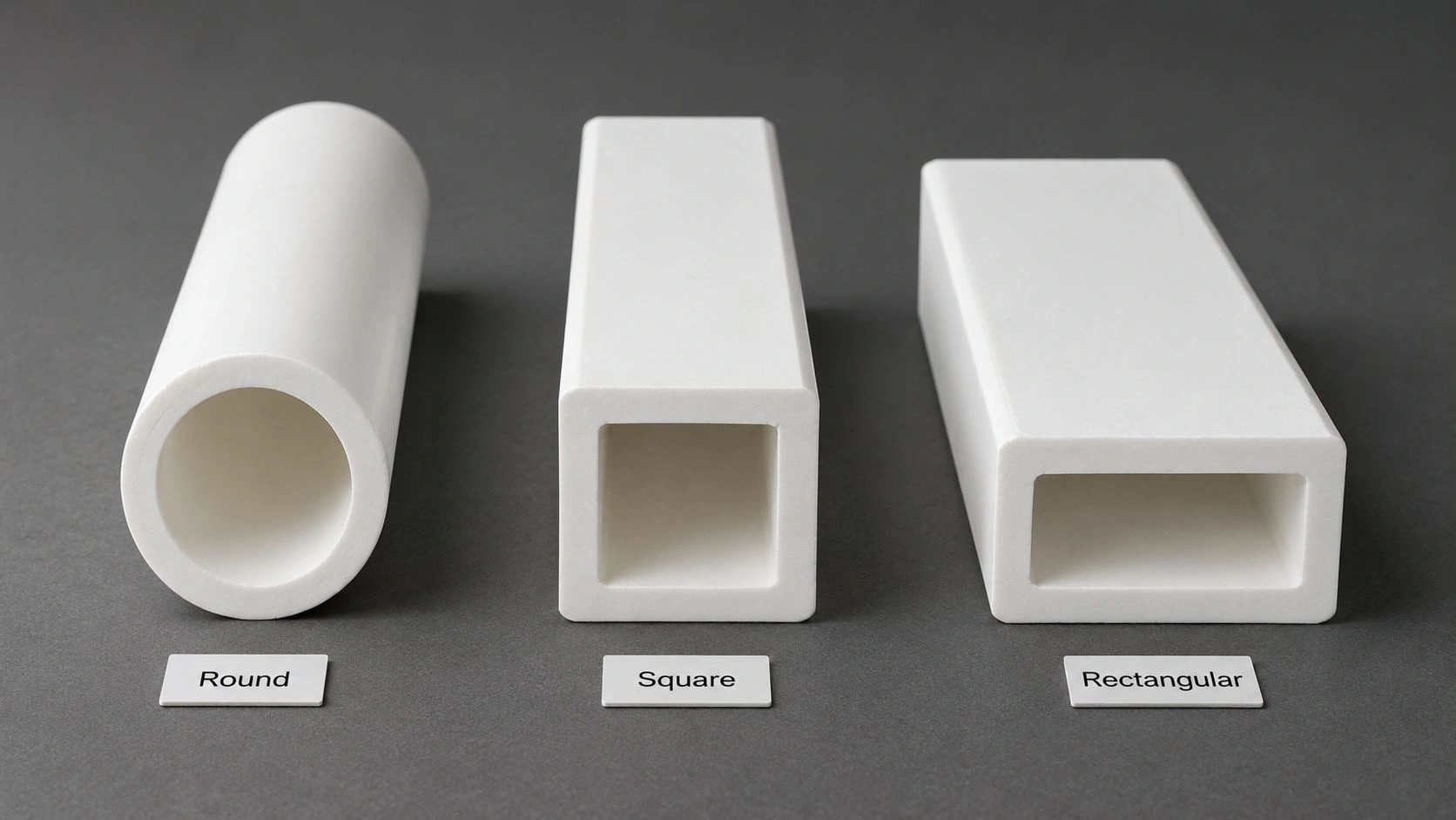
Square cross-section adds a second risk layer that round tubes do not share: corners and flat faces. Four corners running the full tube length provide four zones where edge chips, contact stress, and clamping damage can concentrate. Four flat faces must remain aligned in orientation as well as straight along the length — requiring control of both bow and twist as separate specification items.
Alumina provides the electrical insulation, high-temperature stability, hardness, and chemical resistance needed for electrode tube service. But it remains a brittle ceramic, and local edge damage or uneven clamping can become more consequential than the material grade alone. Custom ceramic tube specification guidance consistently identifies straightness, tolerance, surface finish, end treatment, working temperature, and assembly use as necessary quote inputs — which confirms that long square electrode tubes should be ordered as geometry-controlled components, not as catalog stock.
ADCERAX's alumina ceramic tubes and custom ceramic tubes product lines support drawing-based manufacturing for square alumina electrode tubes where length, straightness, and reference-face control are specified as part of the component definition.
Failure and Rejection Modes: Bow, Twist, Edge Chipping, and Handling Fracture
The primary rejection modes for long square alumina electrode tubes are distinct enough that each requires a separate inspection criterion — not a single overall pass/fail visual check.
Bow is a deviation of the tube's centerline or external face from a straight reference over the full length. A bowed tube may appear straight in one orientation but reveal its arc when rotated. For a square tube in a matching square holder pocket, bow prevents full insertion, creates asymmetric contact, and can induce stress concentration at the holder entry points.
Twist is a rotation of the square cross-section along the tube's length — so that the face at one end is angularly offset from the same face at the other end. Twist does not change the tube's centerline, so it may not be detectable from bow measurement alone. For an electrode tube where one face is the active discharge face or the reference seating face, twist rotates that face out of the intended orientation even if the tube is otherwise geometrically correct.
Edge chipping is localized damage at the four exterior corners along the tube length. Chips at non-contact zones may be cosmetic. Chips in seating zones, holder entry points, or near high-voltage tracking paths are functional rejection conditions.
End-face damage shortens the installed length, affects compression against a stop surface, or prevents correct seating at a holder end.
Handling fracture is brittle failure under loading that concentrated stress above the tube's threshold. It commonly occurs when the tube is lifted from one end without distributed support, placed on a hard surface with only point contact at the corners, or clamped unevenly against a rigid fixture.
ASTM C1161 covers flexural strength testing of advanced ceramics using prescribed specimen geometries and fixture spans — confirming the engineering principle that ceramic strength behavior is loading-geometry-dependent. This supports the specification requirement that long square electrode tubes must be handled and supported correctly rather than treated as robust structural beams.
The following table maps each failure mode to its likely cause, diagnostic signature, and prevention direction.
| Failure / Rejection Mode | Likely Root Cause | Diagnostic Signature | Prevention / Specification |
|---|---|---|---|
| Bow | Long unsupported firing, insufficient straightness control | Centerline or face deviates along full length | Define straightness method, reference face, support span |
| Twist | Square faces rotate along length during forming or firing | Holder fit changes by orientation; active face no longer aligned | Specify twist control and face orientation tolerance |
| Edge chipping | Hard contact, poor packing, clamping, local impact | Chips along corners or seating edges | Define edge acceptance zones and padded packing requirement |
| End-face damage | Dropping, point loading, rough cutting or grinding | Shortened installed length or poor seating contact | Specify end condition and end protection during shipping |
| Bore misalignment | Forming variation or insufficient inspection | Conductor does not pass freely or shifts from centerline | Specify bore position/clearance and inspection method |
| Handling fracture | One-end lifting, unsupported span, point loading | Clean break after transport or assembly handling | Require distributed support during handling and padded storage |
| Clamp-induced crack | Uneven holder contact or over-tightening | Crack near contact face or mounting region | Define contact faces and avoid point-load clamping |
Values indicative; verify with supplier-specific drawing review and applicable ASTM/IEC material data.
Why "Looks Straight" Is Not the Same as Assembly-Ready Straightness
The most common inspection error for long square alumina electrode tubes is confirming that the tube looks straight on a flat bench and concluding that it is assembly-ready.
A long square alumina electrode tube can pass a visual bench inspection and still fail the electrode assembly. Bow may be too small to see clearly at one meter distance but large enough to prevent insertion into a 400 mm holder pocket. Twist may be invisible without a reference measurement at both ends. Edge chips at the holder entry corner may be in a shadow during visual inspection but create a seating gap that shifts the electrode position.
The relevant question is not whether the tube looks straight. It is whether the tube keeps the electrode path, discharge face, insulation gap, and holder contact within the equipment's assembly tolerance window over the full installed length. These are three different measurements from the visual impression:
Reference face versus visual face. A square tube has four equivalent faces visually, but in the electrode assembly one face is the reference face that seats against the holder and one is the active face that orients toward the discharge gap. Straightness of the reference face, not the visual centerline, is the functional requirement.
Electrode alignment and insulation gap. A bowed or twisted tube shifts the conductor bore or active electrode face relative to the ground roll or treated material. Even a 0.5 mm shift in active face position at the center of a long electrode tube may affect corona discharge uniformity.
When edge damage is cosmetic versus functional. A chip at the center of the tube length, away from any seating zone or high-voltage path, may be acceptable. The same chip size at the holder entry, seating shoulder, or in the high-voltage tracking path is a functional rejection condition.
IEC 60672-2 confirms that insulating ceramic test results from test pieces are only a guide to finished component properties because components differ in size and shape from standard test specimens. This principle applies directly: material data tells you about the alumina; component inspection and assembly review tell you about the electrode tube.
ADCERAX's electrical ceramics application page covers alumina ceramic components for electrical isolation and electrode assembly roles where these component-level reviews are standard practice.
What to Specify: Straightness, Twist, Edge Condition, and Support Span
The drawing or RFQ should not simply request "long square alumina tube" with overall dimensions. Each of the risk variables identified above requires a specific, measurable control.
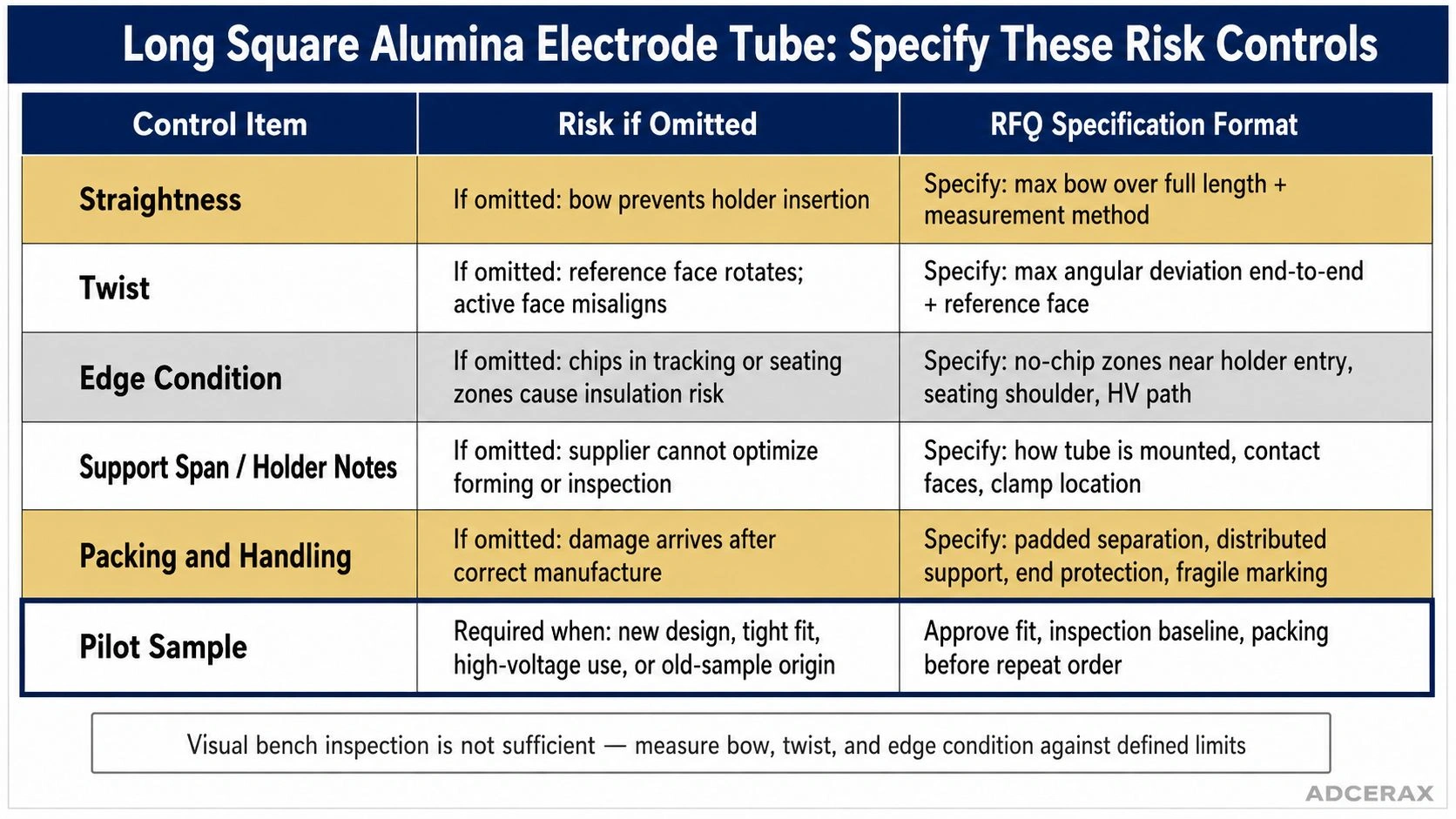
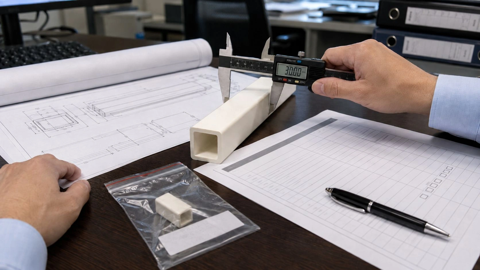
Long square alumina electrode tube RFQs should convert bow, twist, edge condition, support span, packing, and pilot-sample needs into measurable acceptance criteria.
The following matrix maps each design or purchase condition to risk level and required RFQ response.
| Design / Purchase Condition | Risk Level | Why It Matters | RFQ / Inspection Response |
|---|---|---|---|
| Short square tube with loose holder | Lower | Minor bow may not affect fit | Basic dimensions + visual edge check |
| Long square tube with tight holder | High | Bow or twist prevents insertion | Straightness + twist + reference face required |
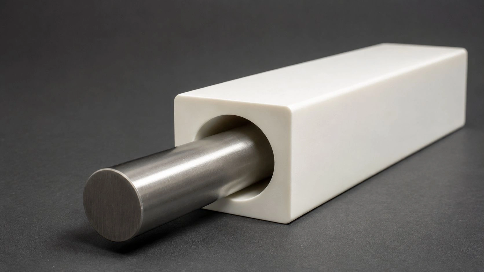
| Long tube with active electrode alignment | High | Centerline shift changes electrode position | Bore alignment + active face orientation required |
| Thin-wall square tube | High | Corners and walls are more damage-sensitive | Wall thickness + edge condition + pilot sample |
| High-voltage path near edges | High | Chips create tracking or clearance risk | Define no-chip zones near active and seating areas |
| Overseas shipping or multiple handling steps | Medium to high | Brittle parts can break after leaving factory | Packing plan + receiving inspection required |
| Repeat order after pilot approval | Lower if drawing frozen | Risk reduces when baseline is controlled | Freeze drawing + inspection checklist |
Straightness specification: State the maximum bow allowed over the full tube length and the measurement method — typically a gap measurement between the tube's reference face and a flat surface at specific intervals along the length. Separate bow measurement from twist measurement.
Twist specification: State the maximum angular offset between reference face orientation at the two ends of the tube. A twist of 1° over 500 mm is very different from 1° over 100 mm; state the tube length in the same requirement.
Edge condition: Identify which edge zones are no-chip zones — typically the holder entry points, seating shoulders, and high-voltage clearance zones. Chips outside these zones may be acceptable within a defined chip size limit.
Support span and clamping notes: Describe how the tube will be mounted in the electrode assembly — inserted into a square holder pocket, clamped at two points, or otherwise supported — so the supplier and inspector understand which geometry controls are functionally critical.
ASTM C1239 covers statistical reporting of uniaxial strength data for brittle advanced ceramics, reinforcing that ceramic failure is flaw-sensitive and statistically distributed. This means a pilot sample and inspection protocol are more reliable risk controls than assuming a correct material grade alone eliminates failure risk.
ADCERAX's industrial alumina tube applications page covers alumina tube service in high-temperature, electrical, and industrial applications where these specification controls apply.
Handling, Packing, and Pilot Approval Checklist for Long Square Alumina Tubes
Long square alumina electrode tubes require handling and packing controls as part of the procurement specification — not as an afterthought.
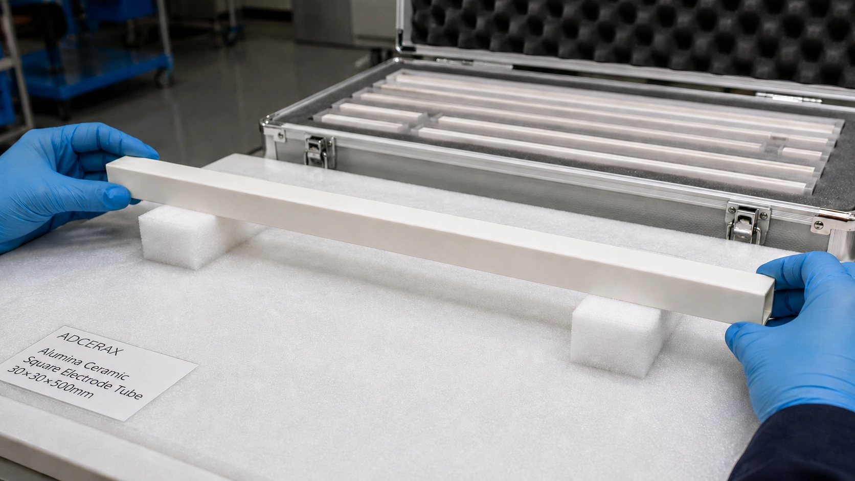
Padded separation, distributed support, and protected handling reduce edge chipping and transport fracture risk before assembly.
During manufacture and pre-shipment inspection, confirm:
- Bow measurement over the full tube length, with the measurement method stated
- Twist measurement at both ends relative to a reference face
- Edge inspection of all four corners, with no-chip zones identified
- End-face condition — chamfer, squareness, and protection requirement
- Bore clearance check — conductor pass-through or bore position inspection
- Wall thickness measurement at each face for square sections
Packing requirements to specify in the RFQ:
- Padded separation between tubes — foam, felt, or soft wrap; not paper or bare cardboard
- Distributed support along the tube length — not point contact at corners or ends only
- End protection — foam plugs, end caps, or capped tubes inside the carton
- Carton or crate design that prevents lateral movement and corner impact during transport
- Labeling that identifies fragile ceramic and orientation requirements
During receiving inspection:
- Check bow and twist before removing from packaging
- Inspect corners and seating edges for chipping
- Verify bore clearance before passing to assembly
- Check face orientation — confirm reference face is identifiable and undamaged
- Record lot number, supplier, and inspection result before installation
Pilot sample approval:
For new designs, new suppliers, or replacement of legacy parts from an old sample or photo, approve a pilot sample before releasing the production quantity. Confirm holder fit, bore clearance, reference face alignment, bow, twist, edge condition, and packing method. Freeze the final drawing and inspection checklist after the pilot sample is approved.
Specifying a long square alumina ceramic electrode tube? Send the drawing or sample, square section size, bore dimensions, total length, straightness and twist requirement, edge-condition notes, holder pocket dimensions, operating temperature, electrical insulation requirement, and whether a pilot sample is needed. ADCERAX engineers confirm feasibility, available manufacturing routes, straightness capability, and packing plan — no order commitment required at this stage.
Frequently Asked Questions
Why are long square alumina ceramic electrode tubes harder to handle than short tubes?
Long square tubes are more sensitive because length increases the effect of bow, twist, and unsupported-span loading — small variations that are tolerable in short sections become significant over a long span. Square corners also provide four concentration points for edge chipping if the tube contacts a hard surface during handling. Always support long tubes at multiple points and use padded surfaces.
Is straightness more important than material grade for long alumina electrode tubes?
Both matter, but straightness can be the immediate assembly-control variable. A high-purity alumina tube may still be rejected if bow, twist, bore alignment, or reference-face orientation prevents correct installation in the holder. Material grade alone does not guarantee geometric suitability.
What should be included in the RFQ for long square alumina ceramic tubes?
Include square section size, bore size and position, wall thickness, total length, maximum allowed bow with measurement method, maximum allowed twist, corner radius, no-chip zone definition, end-face requirement, reference face identification, holder pocket dimensions if known, operating temperature, electrical requirement, packing method, and pilot sample plan.
How can edge chipping be controlled during shipping and handling?
Use padded separation between tubes, distributed support along the tube length, end protection, and carton design that prevents lateral movement and corner impact. During receiving inspection, check corners, seating edges, end faces, and high-voltage clearance zones before installation.
When is a pilot sample necessary for long square alumina electrode tubes?
A pilot sample is recommended when the tube is long (over approximately 300–400 mm), thin-walled, tightly fitted to a holder, orientation-sensitive, used in high-voltage service, or manufactured from an old sample or photo instead of a complete approved drawing. Approve fit, inspection baseline, and packing method before ordering the repeat production quantity.