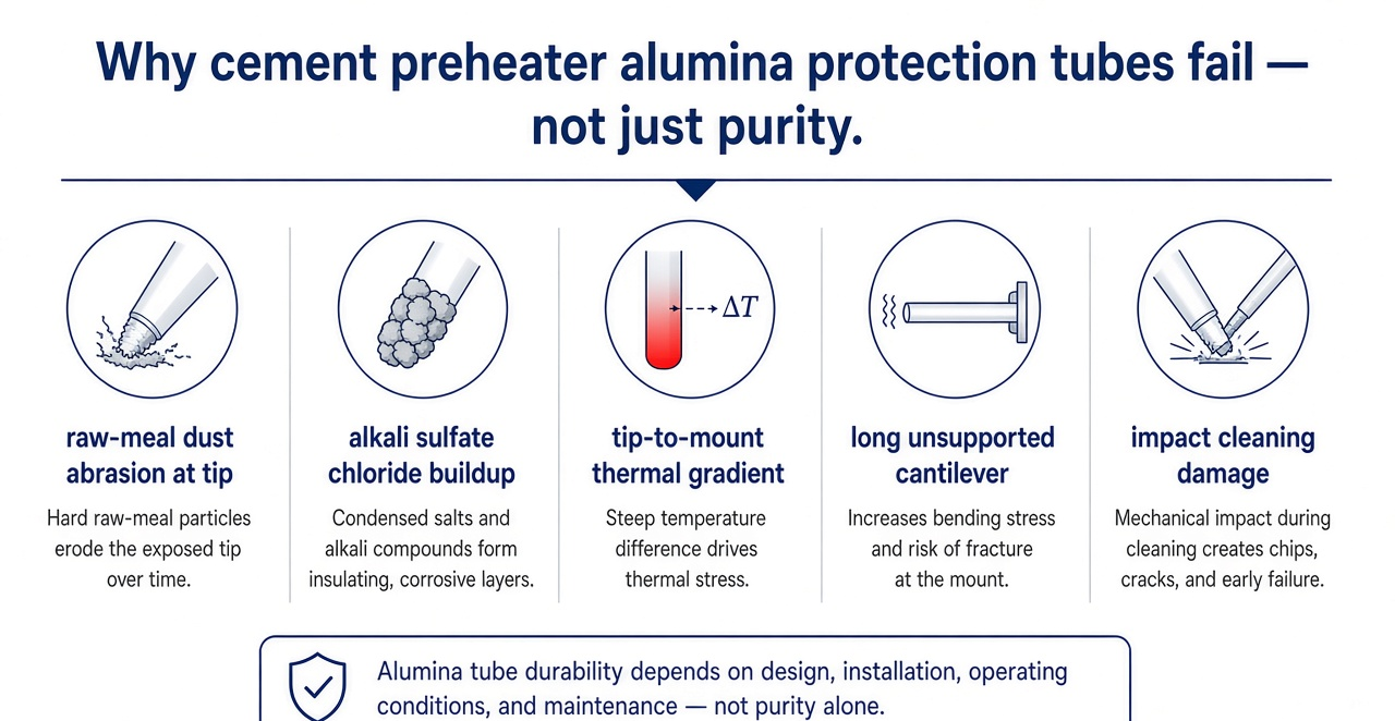
Alumina protection tubes can serve cement kiln preheater thermocouple duty, but service life is usually limited by raw-meal dust abrasion, alkali/chloride/sulfate buildup, the hot-tip to cold-mount thermal gradient, unsupported insertion length, and cleaning impact—not by the grade's long-term temperature selection ceiling alone. A 99.7% alumina screen is a practical starting point; 99.5% alumina may also be evaluated in parallel. For reviewable OD/ID/wall/length ranges and the closed-end alumina protection tube grade catalog that supports preheater RFQs, start from the alumina tube grade catalog for thermocouple protection review.
This page is for cement plant instrumentation and maintenance engineers, and for buyers who must decide when an alumina thermocouple protection tube is enough, when a thicker wall or shorter cantilever is required, when a SiC outer tube or metal well belongs in the route, and which duty fields must appear on the RFQ. It is not a lab-furnace Spec Logic article, not a sizes catalog, and not a manufacturing deep dive. Keep head-term alumina tube(s) traffic on the product catalog; this article owns the cement kiln / preheater protection-tube scene.
3-Minute Decision: Alumina Protection Tube in Cement Preheater?
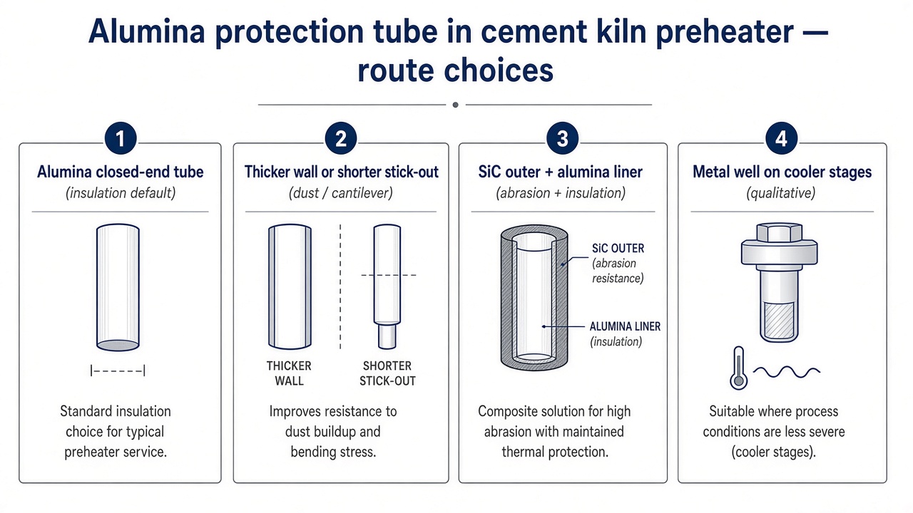
- Moderate hot gas, dust not aimed at the tip, insulation priority → alumina is a fair first review. Default RFQs start at 99.7% alumina. Cost-sensitive industrial screen where purity is not the life limiter → 99.5% alumina is acceptable to evaluate in parallel.
- High-velocity raw meal aimed at the tip, or frequent mechanical cleaning geometry and position first. Thicken the wall, shorten unsupported length, relocate the probe, or add a tougher outer tube. Do not expect a purity step alone to stop tip wear or knock cracks.
- Abrasion plus thermocouple electrical insulation both required → evaluate a double-wall route qualitatively. Tough outer tube (often SiC or metal) with an alumina inner liner for insulation. Response slows; dimensions grow; treat as a system review, not a drop-in single tube.
- Cooler upper cyclone stages → a metal thermocouple well can be evaluated qualitatively. Do not treat metal as a universal preheater answer; dust, buildup, and peak temperature still decide.
- Grade never "repairs" flange restraint cracks or cleaning-impact cracks. Fix mounting clearance, support, and cleaning practice before another purity upgrade.
Cement Preheater Duty (Qualitative)
A preheater protection tube isolates the thermocouple from hot gas, dust, chemical deposits, and mechanical shock. In cement kiln preheaters that duty is industrial, dusty, and chemically cyclic—not a clean laboratory furnace well. Five mechanisms dominate field failures:
- Dust path. Raw-meal particles can scour the tip and outer wall wherever gas velocity aims at the probe. Thin walls and long cantilevers fail earlier under the same dust load.
- Alkali / chloride / sulfate buildup. Circulating salts deposit on cooler surfaces of the tube and mounting hardware. Buildup changes local heat transfer, can bridge clearances, and invites aggressive cleaning that chips or cracks the ceramic.
- Tip-to-mount thermal gradient. The immersed tip runs much hotter than the flange or cold-end mount. That axial gradient, plus any hard clamp at the cold end, drives thermal stress even when the peak tip temperature sits inside the grade's selection ceiling.
- Unsupported insertion. Long probes without intermediate support act as cantilevers under gas flow, vibration, and cleaning loads. Straightness and wall thickness must be reviewed together with insertion length.
- Cleaning impact. Hammering, scraping, or high-pressure cleaning to remove deposits is a frequent crack source near the tip, mid-span, or flange interface—often misread as "bad alumina."
Within broader industrial furnace ceramics practice, cement preheater probes are treated as constrained, abrasive thermal systems—not as catalog drop-ins sized only by a max-temperature line on a datasheet. Plants that share one probe drawing across several cyclone stages often see stage-specific failures: the same OD and grade can last on a cooler, low-velocity location and fail quickly where dust is aimed at the tip. Treat each stage as its own duty review.
Buildup chemistry also varies with kiln feed and fuel. Chloride-rich or sulfate-rich cycles may leave sticky deposits that force more aggressive cleaning. When cleaning frequency rises, mechanical survival of the protection tube usually matters more than another half-point of alumina purity. Capture that cleaning practice on the RFQ so wall thickness and outer-tube options can be reviewed honestly.
Alumina Material Route and Screening
Use the listed alumina composition groups for comparison. IEC C795 / C799 labels are composition groupings for selection comparison—not cement-kiln duty certificates. Long-term temperature figures below are material selection ceilings, not guaranteed service life under dust, cantilever load, or cleaning impact.
| Al2O3 wt% nom. | IEC | Long-term selection ceiling °C | CTE 10^-6/K (25-800 °C) | Water absorption selection limit % |
|---|---|---|---|---|
| 99.90 | C799 | 1750 | 7.6 | ≤0.01 |
| 99.70 | C799 | 1700 | 7.6 | ≤0.05 |
| 99.50 | C799 | 1650 | 7.6 | ≤0.10 |
| 99.00 | C795 | 1600 | 7.2 | ≤0.10 |
| 95 | C795 | 1400 | 7.6 | ≤0.20 |
Straightness across the listed alumina grades is commonly 1 mm/m against the drawing datum where applicable. Density and flexural figures on the TDS support grade comparison; they are not part allowable stresses for a specific preheater probe.
Scene defaults: cement preheater thermocouple protection with insulation priority → start at 99.7% alumina. Industrial coarse screen when purity is not the life limiter → 99.5% alumina may be reviewed in parallel. Higher-purity alumina is rarely the first lever in dusty cement duty (cleanliness-sensitive furnace work is a different scene). 99.0% alumina can be evaluated for lower-demand locations away from direct dust attack; 95% alumina only for low-requirement reviews.
Alumina vs SiC vs metal vs double wall (qualitative):
- Dense alumina — strong electrical insulation for thermocouples, oxidation stability, closed-end forms available; weaker against high-velocity particle scour and impact cleaning than SiC.
- SiC outer tube — useful where abrasion resistance and toughness matter; at elevated temperature SiC can become electrically conductive enough to risk thermocouple signal integrity, so it is often used as an outer tube with an alumina liner when insulation is required. Do not treat SiC alone as a guaranteed insulated TC well.
- Metal well may suit cooler stages where ceramic abrasion or thermal-shock risk outweighs metal temperature limits; still review dust, corrosion, and peak temperature.
- Double wall — outer tough shell + alumina inner liner for abrasion plus insulation. Expect slower thermal response and a larger OD envelope; RFQ both tubes as a pair.
Where multi-material tube families share a plant line, keep alumina protection-tube RFQs separate from broader ceramic tube catalogs. Closed-end forming and finish state also affect lead time and tolerance; process context for how closed-end tubes are made sits on the manufacturing guide, not on this cement scene page. See Related reading.
Do not invent a cement-specific "life hours" or erosion-rate table from this article. Selection ceilings on the TDS tell you which grade family is thermally plausible; dust path, cantilever length, mounting restraint, and cleaning decide whether that grade survives in a given cyclone. If you need a double-wall envelope, state both the outer and inner OD/ID targets early so the pair can be reviewed as one assembly rather than two disconnected catalog lines.
Do Not Misdiagnose Broken Tubes as "Bad Alumina"
| Signature | Likely cause | First fix |
|---|---|---|
| Crack at flange / cold mount | Hard clamp, zero expansion clearance, or deposit bridge at the mount | Soften restraint; restore axial clearance; clear buildup from the seal stack |
| Tip thinning, blunting, or tip break | Direct dust jet / high local velocity | Thicken wall, shorten stick-out, relocate tip out of the jet, or add tough outer tube |
| Mid-span crack after cleaning | Impact or scrape loads on a long cantilever | Change cleaning method; add support; review wall and unsupported length |
| Ring crack near a support or collar | Point load or locked collar acting as a hidden fixed point | Widen contact; allow slide; remove hard stops |
| Repeated short life after purity upgrades | Geometry / position / cleaning unchanged | Stop purity-only steps; map dust path and mounting first |
Stepping up in alumina purity without fixing insertion, mounting, or cleaning rarely stops these patterns. Bring failure photos that show crack distance from the tip and from the flange; annotate whether deposits were present and how the tube was cleaned. That evidence usually shortens the next RFQ cycle more than another purity step.
Lab-furnace protection-tube Spec Logic is a different decision frame—geometry-before-grade in a clean furnace well—not the dusty preheater scene on this page; use Related reading for that contrast. Long-tube expansion-clearance lessons likewise apply when cold-end mounts lock a long probe; borrow the clearance idea without turning this cement article into an expansion-joint design guide.
RFQ Checklist for Cement Kiln Preheater Protection Tubes
A line that only says "closed-end alumina tube, 99.7%" is not enough. Send duty context with geometry. For a compact industrial quoting field list that complements this scene checklist, see key information for quoting alumina tubes—then add the preheater-specific fields below.
Dimensional review ranges (KB / page review wording—not a blanket guarantee that every OD × wall × length combination ships): OD/ID 2-120 mm; length 10-3500 mm; wall 0.5-20 mm; tolerances up to +/-0.05 mm where drawing and process allow—always review, not guarantee. Long insertions and thin-wall cantilevers require section, straightness, firing, and packaging review.
- Preheater stage / cyclone location and whether the tip sees direct raw-meal flow
- Normal, peak, and upset temperature profile (qualitative bands are fine if instruments are noisy)
- Dust loading and whether abrasion is tip-on, side-on, or intermittent
- Alkali / chloride / sulfate buildup history and cleaning method (manual scrape, air lance, mechanical)
- Insertion length and unsupported length; mounting type; expansion clearance at the cold end
- OD / ID / wall; open or closed-end; multi-bore if used; preferred alumina purity (default screen 99.7% alumina)
- Thermocouple type and whether an insulating liner is required (double-wall intent)
- Failure photos with crack location relative to tip, mid-span, flange, and any collar—plus approximate life in service if known (for diagnosis, not as a supplier life guarantee)
- Quantity / annual need; drawing or old-part photo
Inquiry handling is typically framed as a 24 h response window (not a 24 h quote promise); prototypes and customs follow agreed lead times after drawing review. ADCERAX will not claim drop-in universal replacement for every cyclone stage, unlimited stock of every OD length, or a guaranteed life hours figure for cement preheater dust duty.
FAQ
Is alumina always enough for cement kiln preheater thermocouple protection?
No. Alumina is a strong default when insulation matters and dust is not aimed hard at the tip. High-velocity scour, frequent impact cleaning, or very long unsupported probes often need thicker wall, shorter stick-out, a SiC outer tube, a metal well on cooler stages, or a double-wall design.
Which ADCERAX grade should we write on the RFQ?
Start screening at 99.7% dense alumina for thermocouple protection / insulation-priority preheater duty. Use 99.5% alumina as a parallel industrial screen when purity is not the life limiter. Step to higher-purity alumina only for cleanliness-driven reasons—which are uncommon in dusty cement gas. Grade choice never replaces mounting and dust-path review.
Why did a higher-purity tube still crack at the flange?
Cold-end restraint, deposit bridging, and tip-to-mount gradient stress crack alumina regardless of a small purity step. Soften the clamp, restore clearance, and clear buildup before another grade change.
When do we use SiC outer + alumina liner?
When abrasion toughness and thermocouple insulation are both required. SiC alone can present electrical-conductivity risk to the TC circuit at elevated temperature; an alumina liner restores insulation. Expect a larger envelope and slower response. RFQ both members as one assembly.
What dimensions can be reviewed?
Page/KB review envelope: OD/ID 2-120 mm, length 10-3500 mm, wall 0.5-20 mm, tolerances up to +/-0.05 mm on review (not a blanket guarantee), straightness commonly 1 mm/m across the listed alumina grades. Combination feasibility depends on wall, length, closed-end form, and straightness together.