BN liner tolerance stack-up is the combined dimensional allowance between the boron nitride liner and the outer crucible — including liner OD, liner ID, wall thickness, taper, roundness, straightness, bottom radius, bottom gap, outer crucible ID, thermal expansion mismatch, machining tolerance, and debris or coating allowance. The goal is not a tight room-temperature fit. The goal is a controlled clearance that allows cold assembly, accommodates differential thermal expansion during heating, maintains centered and stable liner positioning, prevents melt ingress behind the liner, and permits post-run removal without cracking the BN liner or jamming the outer crucible. Specifying only the liner OD against a nominal crucible ID produces a system that may assemble cold and fail hot.
That clearance-chain-first framing — not a materials description — is the engineering basis for this guide.
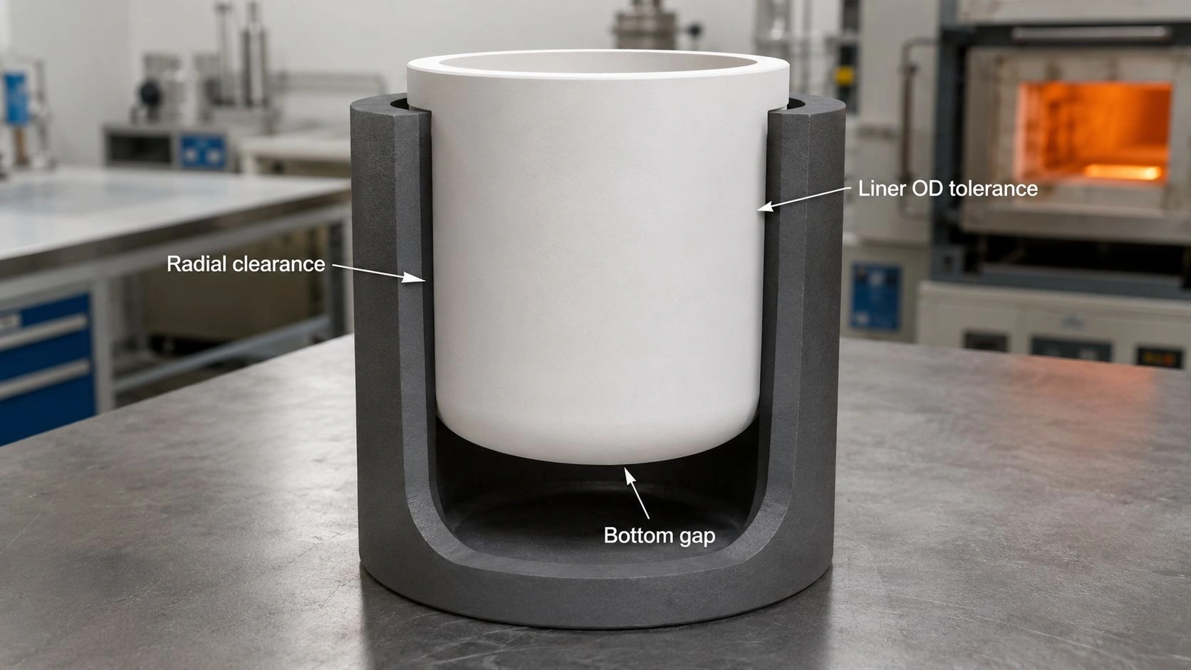
BN liner tolerance stack-up in a composite crucible system involves radial clearance, axial bottom gap, taper angle, roundness, wall thickness, and thermal expansion allowance — cold assembly fit is necessary but not sufficient for safe hot operation and post-run removal.
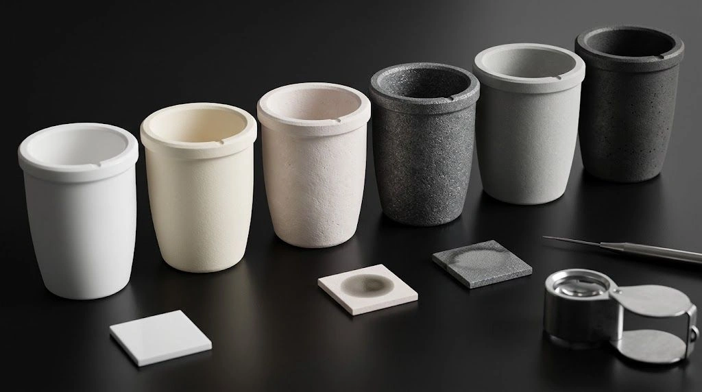
The boron nitride crucible liners at ADCERAX — available in cylindrical, conical, and stepped profiles with IDs from 20 mm to 300 mm for graphite crucibles in titanium melting, powder metallurgy, and laboratory alloy casting, with custom drawing-based geometry — are the starting point for the design decisions described in this guide.
Why BN liners are used in composite crucible systems
A BN liner is selected when the system needs two properties that cannot be provided by one material alone: the clean, non-wetting, low-contamination melt-contact surface of BN, and the structural strength, thermal mass, induction coupling efficiency, or cost effectiveness of another outer material. In many systems, graphite provides the structural body, induction coupling surface, and thermal mass; the BN liner provides the melt-isolation and contamination-control function between the charge and the graphite wall.
BN liner as the melt-contact surface. The inner face of the BN liner is what the molten metal, reactive alloy, or high-purity powder contacts during processing. BN's non-wetting behavior toward most molten metals and its low reactivity with many alloy systems reduce adhesion, sticking, and metal carryover after each run. ADCERAX positions BN liners as protective inserts for graphite crucibles in titanium melting, powder metallurgy furnaces, and laboratory alloy casting — applications where the graphite outer body would contaminate or react with the charge without the BN barrier.
Graphite, ceramic, or metal outer crucible as structural support. The outer crucible provides mechanical support, controls the shape of the assembly, and in induction-heated systems provides the coupling surface that converts RF energy into heat. A full BN crucible can serve this role only when the dimensions are small enough or the budget allows the substantially higher cost of a solid BN body. For larger dimensions, BN's cost and machining time make a lined composite system more practical.
Why liner systems are cheaper or stronger than full BN crucibles. A graphite crucible with a BN liner is typically less expensive than a solid BN crucible of equivalent volume, has better mechanical properties at the outer shell level, and can be more easily sourced in non-standard sizes. The BN liner can be a consumable — replaced between runs — while the graphite shell is reused, further reducing the per-run cost.
Why fit and clearance become the real design problem. Because the liner and outer crucible are not one body, they do not expand, heat, or deform as one unit. BN and graphite have different coefficients of thermal expansion. BN thermal expansion varies significantly by grade and orientation — published property data for BN from multiple sources shows a range of values reflecting differences between grades and the strong anisotropy of the hexagonal BN structure. Graphite has its own anisotropic expansion behavior. At operating temperature, the gap between the liner and the outer crucible may be smaller or larger than at room temperature, and this change determines whether the system jams, rocks, cracks, or performs as designed.
What ""tolerance stack-up"" means for a BN liner
After establishing the role split between the BN liner and the outer crucible, the full dimensional chain that constitutes the tolerance stack-up can be mapped.
[CITE: Published BN property data confirms that BN thermal expansion varies across a broad range depending on grade and crystallographic orientation — with hexagonal BN showing strongly anisotropic expansion behavior along different crystallographic axes — and published crucible selection guidance confirms that thermal expansion mismatch between a crucible material and its contents or interface material can cause cracking on cooldown when the mismatch is not controlled by liner design, clearance, and geometry — establishing that BN liner tolerance stack-up must account for both room-temperature machining tolerances and high-temperature differential expansion, not only the cold-assembly fit.]
The BN Liner Tolerance Stack-Up Variables table maps each dimension to its failure risk and RFQ direction:
| Stack-up variable | Why it matters | Risk if under-specified | RFQ direction |
|---|---|---|---|
| Outer crucible ID | Sets available liner space | Tight fit, jamming, cracking | Provide measured ID and tolerance |
| BN liner OD | Controls radial clearance | Too tight or too loose | Specify OD tolerance and roundness |
| BN liner ID | Controls charge volume | Wrong melt volume or wall too thin | Define usable ID and fill height |
| Wall thickness | Controls strength and heat transfer | Thin wall chips; thick wall changes heat path | Specify minimum wall |
| Taper angle | Controls seating and removal | Wedge-locking after heating | Match outer taper with clearance |
| Bottom clearance | Allows expansion and debris space | Bottom cracking or rocking | Define axial gap |
| Lip height | Controls lifting and melt splash | Chipped lip or poor sealing | Define lip chamfer and tool clearance |
| Roundness/ovality | Controls local contact stress | Point contact and radial cracks | Inspect OD/ID roundness |
| Surface roughness | Controls sliding and residue retention | Jamming, debris packing | Specify only functional zones |
| Thermal expansion allowance | Controls hot fit | Cold fit works, hot fit fails | Review by operating temperature |
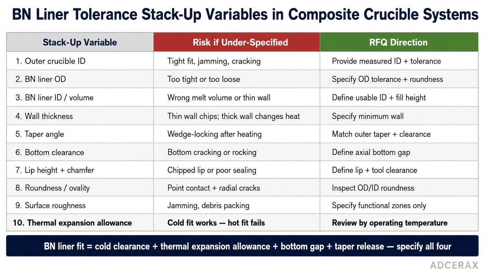
BN liner fit should be specified as a full tolerance stack-up — outer crucible ID, liner OD/ID, wall thickness, taper, bottom clearance, roundness, roughness, and thermal expansion allowance all affect hot fit and removal.
Radial clearance: liner OD vs outer crucible ID. The designed radial clearance — the gap between the BN liner OD and the outer crucible ID — must be large enough to accommodate differential thermal expansion at peak temperature, any roundness deviation in both parts, machining tolerance on both parts, and surface deposits or oxide layers that may form during the run. If the cold-assembly clearance is too small — for example, specifying liner OD = crucible ID − 0.1 mm at room temperature — the high-temperature expansion of the liner or contraction of the outer crucible may close this gap to zero, creating radial compression that can crack the liner.
Axial clearance: bottom gap and lip height. An axial bottom gap between the BN liner bottom and the outer crucible bottom allows the liner to expand freely in the axial direction without being constrained at both ends. A liner that is fully constrained axially — bottomed out at the bottom and clamped at the lip — can develop tensile or compressive axial stress during thermal cycling. The bottom clearance also provides space for debris — metal splatter, residue, powder, or oxides — that would otherwise pack between the liner and outer crucible and either lock the liner in place or create an uneven contact surface.
Taper mismatch and conical liner fit. For conical BN liners, the taper angle must be compatible with the outer crucible taper angle — and the designed cold clearance at the taper surface must survive the thermal expansion regime. A conical liner that is slightly smaller in angle than the outer taper will seat tightly as it expands; a liner that is slightly larger will tend to float upward unless retained. Published BN liner product descriptions from ADCERAX include conical profiles alongside cylindrical and stepped designs, confirming that taper geometry requires specific dimensional matching.
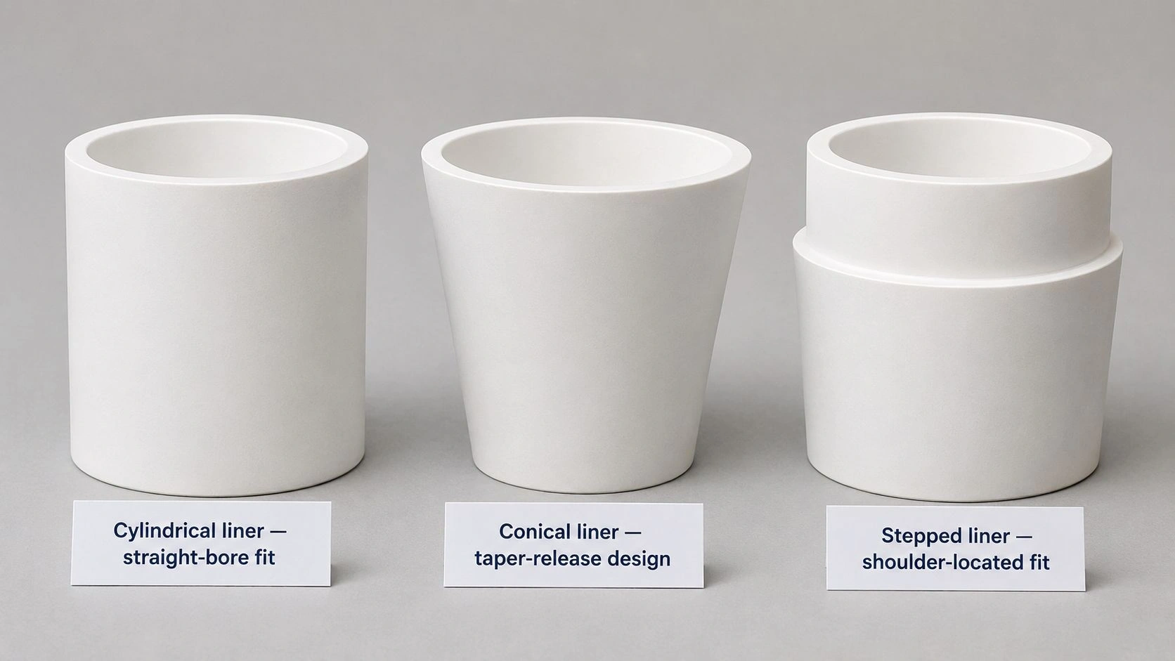
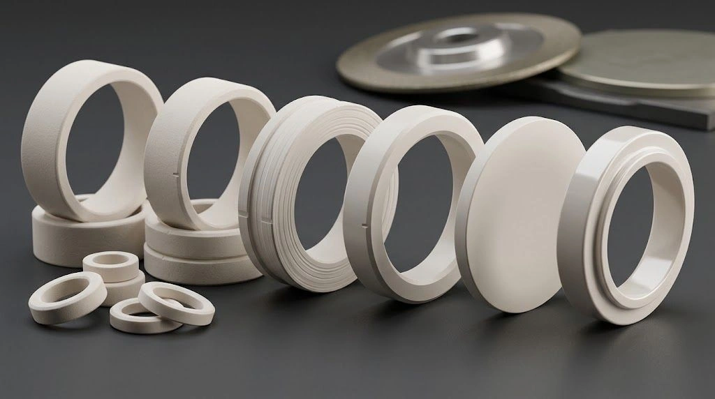
Cylindrical, conical, and stepped BN liners solve different fit problems in composite crucibles — straight-bore fit, taper-release design, and shoulder-located positioning each require separate clearance and removal checks.
Why hot clearance matters more than cold fit. The cold fit determines whether assembly is possible. The hot clearance determines whether the system survives the run, can be removed after cooling, and protects the process from liner cracking or uneven heat transfer. Engineering teams that verify only the cold fit — checking that the liner slides into the outer crucible at room temperature — but do not calculate or measure the hot clearance have incomplete process control.
Outer crucible material changes the stack-up
After understanding the dimensional variables, the specific behavior of the outer crucible material changes how the clearance must be designed.
The Clearance Direction by Outer Crucible Type table maps the main outer crucible materials to their stack-up implications:
| Outer crucible/support | Main stack-up concern | BN liner design direction | Failure to avoid |
|---|---|---|---|
| Graphite crucible | Thermal coupling, oxidation/deposit allowance | Controlled annular gap and removable taper | Stuck liner from residue or melt splash |
| Alumina crucible | Brittle contact stress | Avoid tight radial fit and sharp seating | Ceramic cracking at point contact |
| SiC crucible | Stiff support and thermal gradient | Match taper and avoid hard locking | Liner cracking or uneven heating |
| Metal shell | Higher expansion and mechanical clamping | Avoid shoulder lock and overconstraint | Crushing, lip chipping, locked fit |
| Water-cooled copper support | Large thermal gradient | Isolate BN from hard thermal clamp | Thermal shock or uneven expansion |
| Coated graphite | Coating damage and fit tolerance | Avoid scraping coating during insertion | Coating spall and liner seizure |
Graphite outer crucibles: thermal coupling and deposit allowance. Graphite is the most common outer crucible material for BN liner applications. Graphite's high thermal conductivity provides excellent heat coupling to the BN liner, but graphite can oxidize, erode, and accumulate carbon deposits in non-inert atmospheres. A deposit in the annular gap between the BN liner and graphite outer wall effectively reduces the available clearance over time. The designed clearance should be large enough to accommodate moderate deposit accumulation while still maintaining adequate contact for heat transfer.
Alumina and ceramic outer crucibles: brittle contact stress risk. If the BN liner is slightly oversized or the alumina outer crucible contracts slightly during a firing cycle, point contact between a hard BN liner edge and the brittle alumina outer wall can create a stress concentration that fractures the ceramic. For alumina or SiC outer crucibles, the BN liner OD must be controlled with a softer design philosophy — ensuring that contact, if it occurs, is distributed across a surface rather than concentrated at an edge or high point.
Metal outer shells: expansion and clamping risk. Metal shells expand more than BN at elevated temperature — and if the shell has a shoulder or retaining feature, the expanding metal can clamp the BN liner and prevent it from expanding freely. The result is radial compression on the BN liner during heating and potentially crushing force at temperature. Designing the metal shell without hard retention features — or with a controlled sliding interface — avoids this failure mode.
The BN crucible and custom liner geometries at ADCERAX — including hot-pressed HPBN grades with CNC finishing for dimensional control — and the custom ceramic parts manufacturing service covering drawing-based tolerance, CMM inspection, and first-article validation provide the production context for the tolerance specifications described above.
Do not misdiagnose fit failures as BN material failure
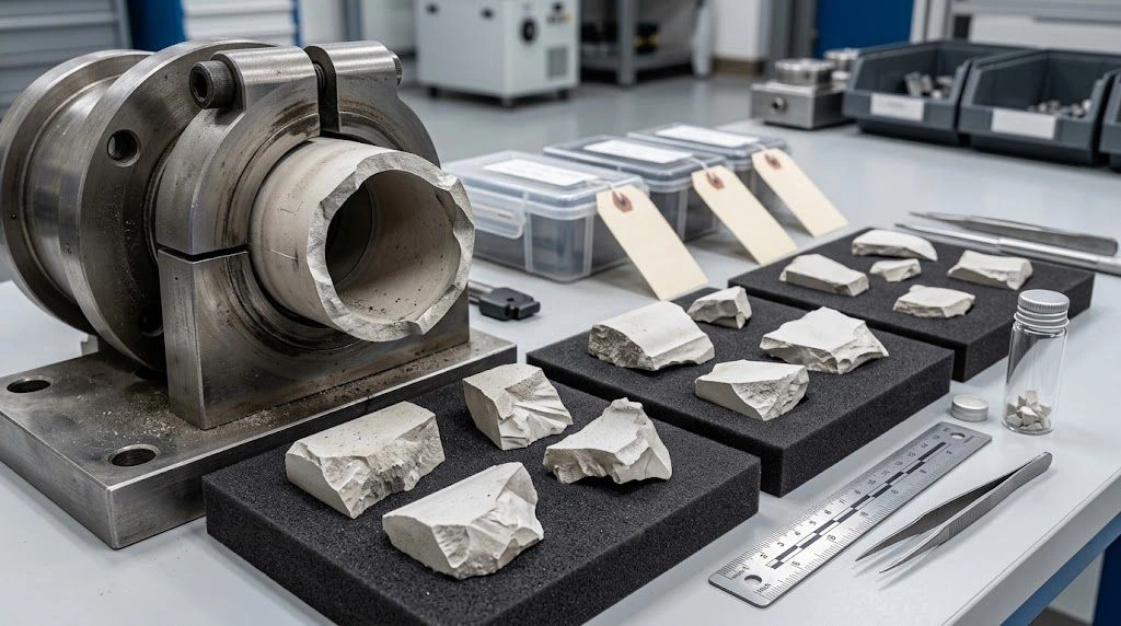
When a BN liner cracks, sticks, tilts, or causes the outer crucible to crack, the BN material quality is one of several possible failure causes — and often not the primary one. Tolerance stack-up and assembly design problems produce failure signatures that look like material failures at first inspection.
Vertical liner cracks from radial compression. A vertical crack — running from the lip of the liner toward the bottom — is the characteristic signature of radial compression. This occurs when the liner has too little clearance to the outer crucible at operating temperature, and the differential expansion closes the gap and squeezes the liner. The crack propagates under tensile hoop stress on the outer surface of the BN liner. Reviewing the cold clearance, calculating the hot clearance, and increasing the designed gap resolves this failure mode.
Bottom cracks from zero axial clearance. A crack at or near the liner bottom — running horizontally or in a ring around the lower zone — typically indicates axial constraint. If the liner is bottomed out against the outer crucible with no designed gap, axial thermal expansion creates compressive loading on the bottom geometry. Adding a specified bottom gap resolves this.
Stuck liners from melt ingress or residue packing. If melt material, oxide, salt, or fine powder enters the annular space between the BN liner and the outer crucible during a run, it can solidify during cooling and mechanically lock the liner in place. BN's non-wetting behavior prevents melt adhesion to the liner inner surface, but it does not prevent material from entering the clearance space from the top. A designed lip geometry that seals the entry point, combined with adequate annular clearance for any material that does enter to remain movable, addresses this failure mode.
The Failure Diagnosis Matrix maps observed composite crucible problems to better diagnostic questions:
| Observed problem | Common assumption | Better diagnostic question |
|---|---|---|
| BN liner cracks vertically | BN material is weak | Was radial clearance too tight at hot condition? |
| BN liner cracks at bottom | Poor liner quality | Was there bottom clearance or did the liner bottom out? |
| Liner sticks after cooling | BN lost non-wetting behavior | Did metal, oxide, salt, or powder enter the annular gap? |
| Liner tilts during heating | Bad machining | Was radial clearance too large or bottom seating uneven? |
| Melt leaks behind liner | BN liner failed chemically | Was the lip design, fill height, or clearance path open? |
| Outer crucible cracks | BN liner expanded too much | Was contact localized at taper or bottom radius? |
| Lip chips during removal | Brittle BN | Was removal tool clearance designed into the lip? |
| Heat distribution changes | BN liner material problem | Did loose fit create uneven contact or air gaps? |
Diagnosis should be based on crack location, deposit analysis, fit measurement, and thermal history before any material grade change is specified.
RFQ checklist for BN liner tolerance stack-up
A complete RFQ for a BN liner in a composite crucible system must provide both the BN liner drawing and the outer crucible drawing — because the liner tolerance cannot be judged without the mating part geometry and the operating temperature differential.
[CITE: Engineering guidance on BN crucible liner specification for composite crucible systems confirms the complete RFQ sequence: outer crucible material with ID and ID tolerance at top/mid/bottom, depth and taper angle, inner surface roughness, BN liner OD/ID/wall thickness/height/lip design/bottom shape/bottom clearance, target radial clearance with thermal expansion allowance, operating temperature with ramp/cool/cycle count, atmosphere, melt or powder chemistry, fill level, induction or resistance heating method, expected residue, cleaning method, and whether liner removal after each run is required — because outer crucible geometry, operating temperature, and process chemistry together determine whether the proposed clearance is safe for the specific composite system, and a supplier who receives only ""BN liner 100mm OD × 90mm ID × 120mm height"" cannot confirm clearance, taper release, or removal strategy without the remaining composite crucible context.]
| RFQ field | Why it matters | Recommended wording |
|---|---|---|
| Outer crucible material | Controls expansion and contact stress | ""Graphite/alumina/SiC/metal/coated graphite"" |
| Outer ID and tolerance | Baseline of radial clearance | ""Measured ID at top/mid/bottom if possible"" |
| BN liner OD | Controls fit | ""OD with tolerance, roundness, and datum"" |
| Liner ID/volume | Controls charge capacity | ""Usable volume and maximum fill height"" |
| Wall thickness | Controls strength and heat transfer | ""Nominal and minimum wall thickness"" |
| Taper/cone angle | Controls seating and release | ""Outer crucible taper and liner taper separately"" |
| Bottom shape | Controls rocking and thermal stress | ""Flat, radius, conical, stepped, bottom gap"" |
| Operating temperature | Controls hot clearance | ""Peak, dwell, ramp, cooling, cycle count"" |
| Atmosphere | Controls oxidation and residue | ""Vacuum/Ar/N₂/air/reducing/reactive gas"" |
| Melt/powder chemistry | Controls wetting and residue | ""Metal/alloy/salt/oxide/powder and reaction products"" |
| Removal requirement | Determines fit strategy | ""Single-use liner or removable after every run"" |
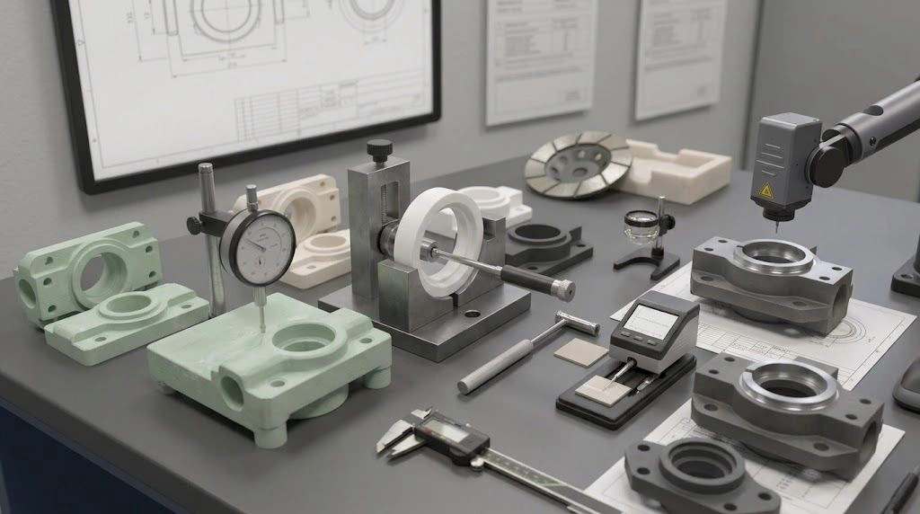
| Inspection method | Prevents acceptance disputes | ""CMM, bore gauge, roundness, visual, trial fit"" |
RFQ fields are the minimum for a BN liner composite crucible inquiry; add a complete BN liner drawing and the outer crucible drawing or measured ID data for a complete engineering review.
For first-time BN liner deployment in a composite crucible or any new crucible geometry, running an empty trial heat cycle — assembling the liner at room temperature, heating to operating temperature in the designed atmosphere, cooling, and attempting removal — is the most reliable qualification step before charging with the actual melt or powder.
Evaluating a BN liner for a graphite, ceramic, or metal crucible? Share the outer crucible drawing or ID measurements, BN liner drawing, target radial clearance, bottom gap, taper, operating temperature, atmosphere, melt chemistry, fill level, and whether the liner must be removed between runs. ADCERAX can review whether a cylindrical, conical, stepped, HPBN, PBN, or alternative liner geometry fits the composite crucible system; turnaround depends on inquiry complexity — no commitment required at this stage.
Frequently Asked Questions
What is BN liner tolerance stack-up?
It is the combined clearance and tolerance relationship between all mating dimensions in a composite crucible assembly — including the BN liner OD/ID, the outer crucible ID, wall thickness, taper angle, roundness, bottom gap, and thermal expansion allowance. The stack-up defines whether the system assembles correctly at room temperature, operates correctly at elevated temperature, and can be disassembled after the run without cracking or jamming.
How tight should a BN liner fit inside a graphite crucible?
It should not be a press fit. A controlled radial clearance — large enough to accommodate differential thermal expansion at operating temperature, roundness deviations in both parts, machining tolerances, and moderate deposit accumulation — is required. The appropriate clearance depends on the liner diameter, operating temperature, outer crucible material, and whether removal after each run is required. Providing the outer crucible ID and operating temperature allows the supplier to recommend the appropriate cold clearance.
Why do BN liners crack after heating?
Common causes include insufficient radial clearance that causes radial compression from thermal expansion mismatch, zero bottom gap causing axial compression, taper wedging, outer crucible distortion that closes the clearance locally, residue packed into the annular gap creating mechanical constraint, or thermal shock during rapid heating. BN material quality should be inspected, but tolerance stack-up design is the more frequent root cause of post-heating cracking.
Is BN easy to machine to tight tolerances?
Yes. BN is widely recognized for machinability and can be produced in close-tolerance profiles including cylindrical, conical, and stepped shapes. However, close machining tolerance on the liner body does not replace the need to design adequate thermal expansion allowance and removal clearance into the composite crucible system. The liner tolerance and the assembly clearance are separate engineering decisions.
Should the BN liner bottom touch the outer crucible bottom?
Usually not as an unconstrained contact. A designed axial bottom gap allows the liner to expand freely in the axial direction without developing compressive stress at the bottom. If bottom contact is needed for controlled heat transfer, the contact geometry should be a designed seating surface — a ring or flat — rather than an accidental point contact that creates variable constraint.
What information should I send to a supplier for a BN liner?
Send both drawings: the BN liner drawing and the outer crucible drawing or measured ID data. Include liner OD/ID/wall/height/taper/bottom design, outer crucible material/ID/taper/bottom radius, target radial clearance, bottom gap design, operating temperature with ramp and cooling rates, atmosphere, melt or powder chemistry and fill level, removal requirement, and photographs if replacing a cracked or stuck liner from a previous design.
"