Alumina Ceramic is frequently selected when photovoltaic production faces instability caused by thermal distortion, mechanical fatigue, or inconsistent component lifetimes across high-temperature process stages.
This article examines how Alumina Ceramic functions as a structural and thermal stabilizer within photovoltaic manufacturing equipment. It focuses on engineering behavior, long-term reliability, and process-level consequences rather than material theory alone.
As photovoltaic manufacturing scales toward higher throughput and longer furnace duty cycles, material behavior increasingly defines equipment stability. Therefore, understanding how Alumina Ceramic performs under real production stress becomes essential before evaluating design or procurement decisions.
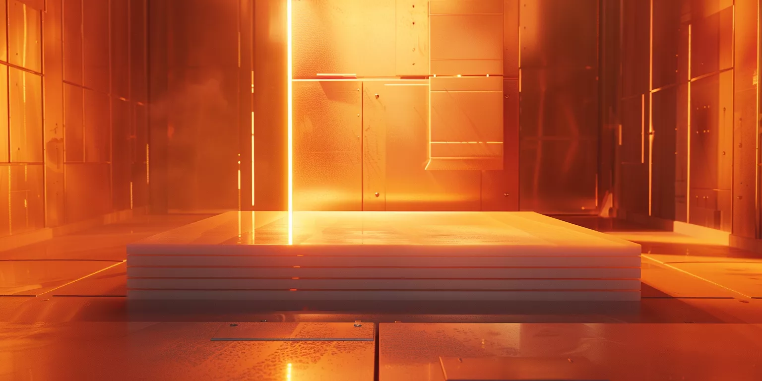
Before examining specific photovoltaic components, it is necessary to clarify how Alumina Ceramic is physically integrated into production equipment. This section establishes the structural and functional context that governs its performance across high-temperature PV lines.
Functional Integration of Alumina Ceramic within Photovoltaic Production Equipment
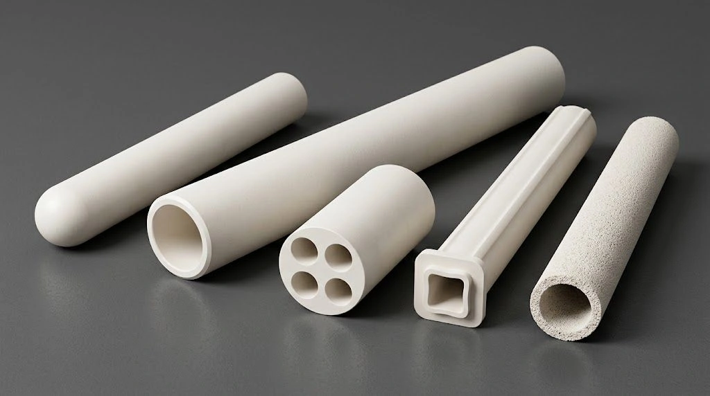
Alumina Ceramic — see also photovoltaic ceramics, alumina boats / setters, and drawing·purity·duty·qty RFQ (tube form: alumina tubes when the duty is tubular) — does not appear in photovoltaic manufacturing as a standalone material choice. Instead, it is embedded within production equipment where thermal exposure, mechanical load, and dimensional control intersect. Consequently, its role must be understood at the equipment level rather than at the material datasheet level.
Moreover, these ceramic components often operate continuously under conditions that amplify small deviations over time. Therefore, functional integration determines whether Alumina Ceramic supports stable production or gradually becomes a limiting factor.
Where Alumina Ceramic Physically Appears in PV Manufacturing Lines
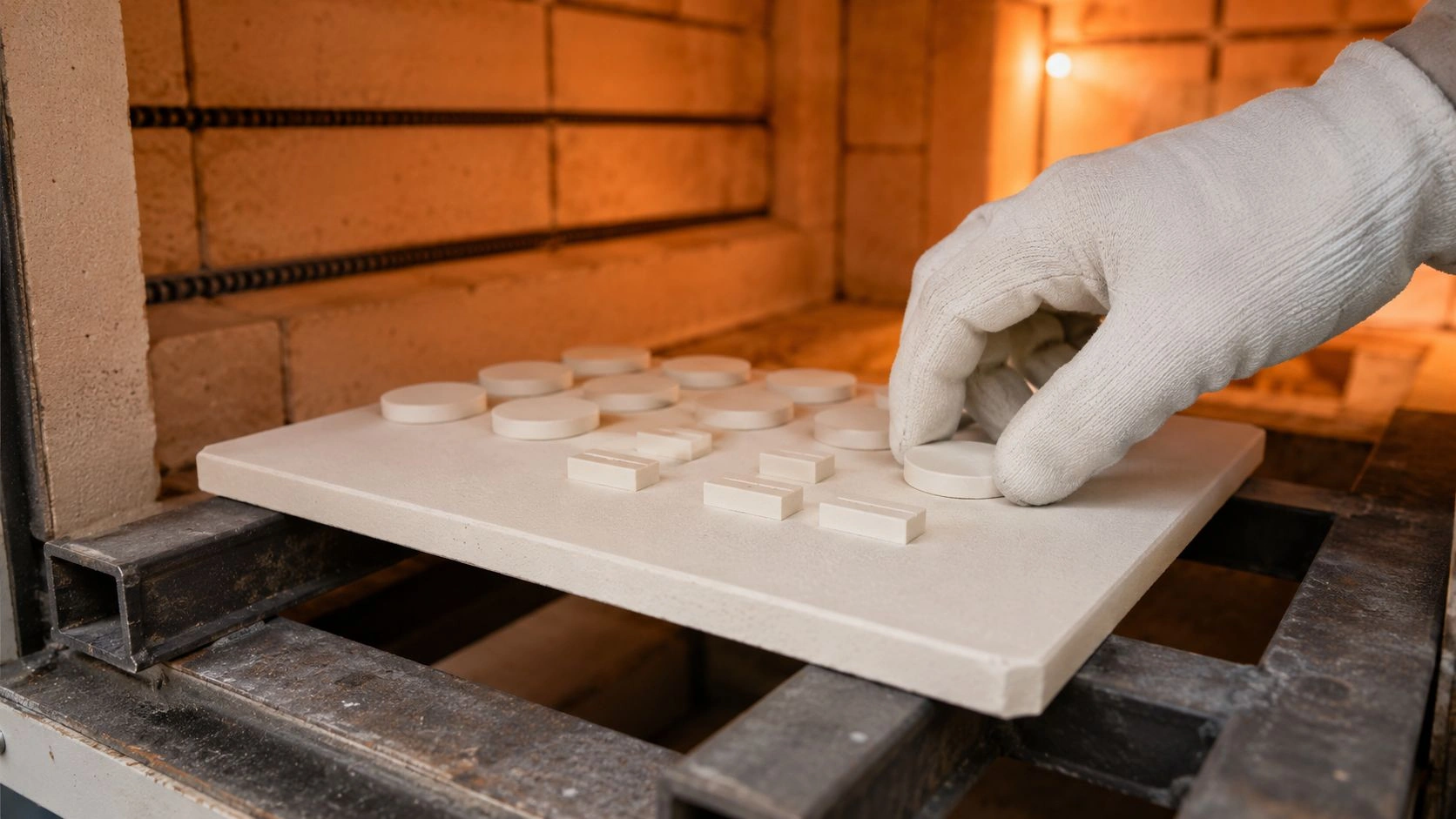
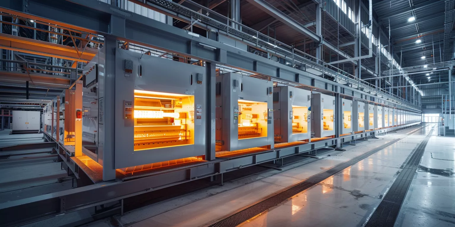
Alumina Ceramic is most commonly found in diffusion furnaces, firing systems, and high-temperature handling zones within photovoltaic production lines. In these areas, components such as diffusion boats, setter plates, and structural supports typically see a process-typical PV exposure band around 900–1,300 °C for extended runs — confirm furnace profile, atmosphere, and grade on the duty RFQ. Consequently, dimensional stability becomes more critical than short-term strength.
As an illustrative handling example, multicrystalline lines near ~1,150 °C may run boats with high wafer counts per batch while holding positional tolerance in a sub-millimeter band over many cycles — confirm boat drawing and cycle duty on RFQ. Metallic alternatives often distort sooner under similar thermal profiles. As a result, ceramic integration can reduce downtime and wafer handling errors when geometry is locked to duty.
From an engineering perspective, physical placement within hot zones defines service life expectations. Therefore, Alumina Ceramic must be evaluated based on its interaction with furnace geometry and loading patterns rather than isolated laboratory testing.
How These Components Interact with Wafers and Thermal Zones
Within diffusion and firing furnaces, Alumina Ceramic components directly influence wafer spacing and thermal uniformity. Even minor geometric drift can alter local heat transfer conditions. Consequently, uniformity across wafer stacks depends heavily on ceramic dimensional retention.
Illustrative thermo-mechanical coupling: a ~0.5 mm carrier deformation can be associated with roughly ~6 °C batch temperature spread in some continuous diffusion layouts — not a precision mapping SLA; confirm on furnace geometry. Moreover, such variation can correlate with dopant diffusion inconsistency and measurable efficiency deviation downstream. As a result, ceramic behavior indirectly affects electrical performance metrics.
Practically, Alumina Ceramic acts as a silent interface between furnace atmosphere and wafer processing. Therefore, its interaction with thermal zones must remain predictable throughout extended production cycles.
Why Structural Stability Is Central to These Functional Roles
Structural stability defines whether Alumina Ceramic fulfills its intended role or becomes a gradual source of process drift. Unlike components subject to rapid failure, ceramic degradation often manifests slowly. Consequently, unnoticed deformation accumulates until process control thresholds are exceeded.
Screening-typical creep guidance used on continuous PV lines often treats creep strain around ≤0.1% over ~500 h as alignment-preserving, while values trending above ~0.2% are associated with progressive wafer misplacement — confirm T/load/grade on the TDS; not a contract creep limit. Such misalignment often coincides with increased reject rates rather than immediate equipment failure. As a result, material selection errors surface as yield losses rather than mechanical breakdowns.
Ultimately, structural stability enables Alumina Ceramic to function as a long-term production asset. Therefore, its integration must be assessed through sustained operational performance rather than initial installation condition.
Structural and Functional Characteristics of Alumina Ceramic in PV Equipment
| Parameter | Typical Value | Relevance to PV Equipment |
|---|---|---|
| Continuous operating temperature (°C) | process-typical ~1,200–1,300 — confirm profile | Supports long furnace cycles |
| Creep strain at 1,200 °C (%) | screening-typical ≤0.1 — confirm TDS | Preserves geometry over time |
| Flexural strength retention (%) | illustrative ≥85 after extended cycling — confirm duty | Supports structural reliability screening |
| Thermal expansion coefficient (×10⁻⁶/K) | 7.5–8.5 | Maintains alignment consistency |
| Dimensional deviation after cycling (mm) | process-typical ≤0.3 — confirm inspection | Controls wafer positioning |
Before evaluating specific component designs, it is necessary to understand the physical stresses that dominate photovoltaic production environments. This section examines how thermal and mechanical realities shape material suitability over extended operating cycles.
Thermal and Mechanical Realities Shaping Material Selection in PV Processes
Photovoltaic manufacturing subjects equipment materials to prolonged thermal exposure combined with repeated mechanical interaction. Consequently, material performance must be judged under sustained stress rather than peak-condition testing alone.
Moreover, thermal and mechanical effects often act simultaneously. Therefore, materials that perform well under isolated conditions may still fail when these stresses overlap across continuous production schedules.
Continuous High-Temperature Exposure in Diffusion and Firing Furnaces
Diffusion and firing furnaces commonly operate in a process-typical PV exposure band around 900–1,300 °C — confirm profile + atmosphere + grade — often without extended cooldown periods. Under such conditions, Alumina Ceramic must resist both thermal softening and time-dependent deformation. Consequently, creep resistance becomes a primary selection criterion.
As a grade-typical illustrative example on a phosphorus diffusion line near ~1,050 °C, higher-purity alumina carriers can hold dimensional change in a low-fraction percent band after hundreds of operational hours, while lower-grade ceramics may exceed ~0.2% deformation in a similar window — confirm microstructure + duty; not a plant-test proof. Recalibration interval extension is an illustrative maintenance benefit, not a guaranteed shortening ratio.
From an operational standpoint, continuous exposure amplifies minor material weaknesses. Therefore, sustained thermal performance outweighs short-term thermal shock resistance in PV equipment.
Repeated Thermal Cycling During Loading and Maintenance
Although furnaces operate continuously, loading, unloading, and maintenance introduce thermal cycling. Components may experience temperature swings of 300–500 °C within short timeframes. Consequently, resistance to thermal fatigue becomes essential.
Production experience on automated loading systems shows alumina components cycled from ~1,200 °C toward cooler handling temperatures can endure extended cycle counts without visible cracking when cooling is even — illustrative service observation; confirm QA plan. Microcrack density rises when cooling is uneven across surfaces. As a result, controlled cooling protocols prove as important as material choice itself.
Practically, thermal cycling stresses grain boundaries rather than bulk material. Therefore, microstructural stability defines long-term reliability under repetitive temperature changes.
Mechanical Loads from Wafer Stacks and Handling Systems
In addition to thermal effects, Alumina Ceramic components bear mechanical loads from stacked wafers and automated handling equipment. Typical carrier loads range from 8 kg to 15 kg, applied continuously at elevated temperatures. Consequently, elastic modulus stability under heat becomes a critical factor.
Material-behavior-typical screening: components that retain high elastic modulus at ~1,100 °C often hold flatness near a ±0.25 mm class — confirm grade TDS + geometry; not an acceptance package. Conversely, components falling below that retention band can exhibit gradual sagging, leading to wafer contact and surface damage. As a result, mechanical stability directly influenced both yield and equipment wear.
Ultimately, mechanical loads cannot be separated from thermal context. Therefore, Alumina Ceramic must be evaluated as a load-bearing material at temperature rather than under ambient conditions.
Thermal and Mechanical Stress Profile in Photovoltaic Manufacturing
| Stress Factor | Typical Range | Effect on Alumina Ceramic |
|---|---|---|
| Furnace temperature (°C) | process-typical 900–1,300 — confirm profile | Governs creep behavior |
| Thermal cycling amplitude (°C) | 300–500 | Drives fatigue risk |
| Continuous load per component (kg) | 8–15 | Influences deformation |
| Cycle count per year | >2,000 | Accumulates microdamage |
| Cooling rate (°C/min) | 5–20 | Affects crack initiation |
With operating stresses established, attention can now shift to the physical forms Alumina Ceramic takes within photovoltaic equipment. This section connects abstract material behavior to concrete components encountered on production floors.
Photovoltaic Equipment Components Commonly Engineered from Alumina Ceramic
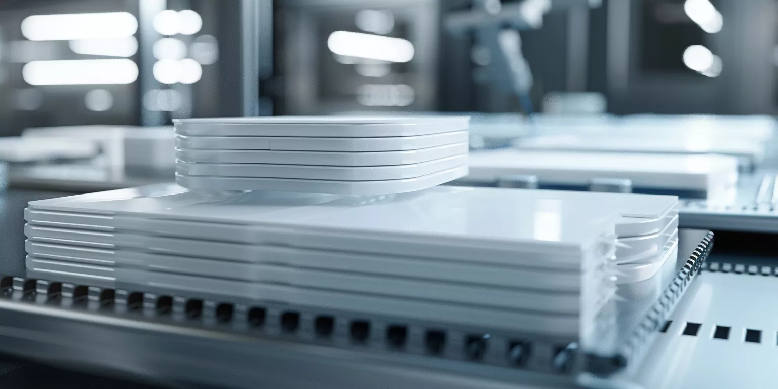
Alumina Ceramic appears in photovoltaic manufacturing through a limited but critical set of component geometries. Although these parts differ in shape and size, they share exposure to identical thermal and mechanical demands. Consequently, component design often dictates whether material advantages are fully realized.
Moreover, experienced engineers evaluate these components not as isolated parts but as contributors to overall process stability. Therefore, understanding their functional roles clarifies why Alumina Ceramic remains prevalent in PV equipment.
Diffusion Boats and Wafer Carriers
Diffusion boats and wafer carriers represent the most visible application of Alumina Ceramic in PV lines. These components hold wafers in precise alignment while passing through high-temperature diffusion zones. Consequently, dimensional accuracy and long-term shape retention directly affect dopant uniformity.
As a process-typical dimensional retention example, boats on high-throughput lines can hold slot spacing near a ±0.2 mm class after extended cycling around ~1,100 °C — confirm inspection plan; not a life guarantee. Operators often report reduced wafer edge chipping versus metallic carriers when geometry is stable. As a result, handling-related yield losses can drop when slot retention is locked to duty.
From an engineering standpoint, these carriers serve as both structural and thermal mediators. Therefore, their performance extends beyond simple wafer support.
Setter Plates and Support Fixtures in Firing Furnaces
Setter plates fabricated from Alumina Ceramic provide flat, thermally stable surfaces during metallization firing. These plates experience continuous load and radiant heat exposure. Consequently, resistance to sagging becomes more critical than peak strength.
Screening-typical setter guidance: creep strain around ≤0.1% over ~500 h is often associated with flatness near a ±0.3 mm class — confirm setter grade + print duty; not a contract creep/life SLA. Plates trending past that deformation band can drive uneven paste sintering and higher contact resistance downstream.
Practically, setter plate stability governs downstream electrical consistency. Therefore, Alumina Ceramic selection directly influences metallization quality.
Structural Supports and Insulating Elements
Beyond direct wafer contact, Alumina Ceramic also functions as structural supports and insulating components within furnaces. These parts maintain furnace geometry and isolate heat zones. Consequently, their failure often affects multiple process stages simultaneously.
Illustrative support stability: ceramic supports can hold positional accuracy near a 0.4 mm class after prolonged exposure around ~1,250 °C — confirm load case. Low thermal conductivity can also provide an illustrative thermal-management benefit on inter-zone heat leak (order-of ~15% in some assemblies) — confirm assembly design. As a result, process control margins can improve across the system when supports stay true.
Ultimately, these less-visible components often determine equipment longevity. Therefore, their role should not be underestimated during system design.
Common Alumina Ceramic Components in PV Manufacturing Equipment
| Component Type | Typical Operating Temperature (°C) | Key Performance Requirement | Observed Service Life |
|---|---|---|---|
| Diffusion boats | process-typical 1,000–1,150 — confirm | Slot stability | screening/illustrative >1,500 cycles — confirm duty RFQ |
| Wafer carriers | process-typical 900–1,100 — confirm | Dimensional accuracy | screening/illustrative >1,200 cycles — confirm duty RFQ |
| Setter plates | process-typical 750–850 — confirm | Flatness retention | screening/illustrative >800 h — confirm duty RFQ |
| Structural supports | process-typical 1,200–1,300 — confirm | Load-bearing stability | screening/illustrative >1,000 h — confirm duty RFQ |
| Insulating spacers | process-typical 900–1,200 — confirm | Thermal isolation | screening/illustrative >1,500 h — confirm duty RFQ |
After examining component forms, the discussion now shifts toward how material behavior translates into measurable production outcomes. This section explains why material-driven effects often determine process consistency and yield stability in photovoltaic manufacturing.
Material-Driven Factors Governing Process Uniformity and Yield Stability
In photovoltaic production, yield losses rarely originate from single-point failures. Instead, they accumulate through subtle material-induced deviations that persist across many cycles. Consequently, Alumina Ceramic performance influences process uniformity long before defects become visible.
Moreover, these effects typically manifest at the system level rather than at individual component boundaries. Therefore, understanding material-driven factors is essential for maintaining consistent electrical output.
Dimensional Drift and Its Effect on Thermal Uniformity
Dimensional drift in Alumina Ceramic components alters local heat transfer conditions within furnaces. Even minimal deformation changes wafer spacing, which directly affects temperature gradients. Consequently, thermal non-uniformity emerges gradually across batches.
Illustrative thermo-mechanical coupling: a ~0.4 mm carrier deformation can be associated with roughly ~5 °C batch temperature spread on some large-format lines — not a precision mapping SLA. Dopant concentration scatter can follow; confirm furnace geometry + inspection. Efficiency consistency can decline despite unchanged setpoints when drift accumulates.
From an operational viewpoint, dimensional drift undermines thermal predictability. Therefore, creep resistance remains a primary driver of yield stability.
Surface Interaction and Wafer Contact Behavior
Surface condition of Alumina Ceramic components influences wafer contact and friction behavior during loading and unloading. Excessive surface roughness increases localized stress, while overly smooth surfaces may reduce positional stability. Consequently, controlled surface finish becomes an overlooked yield factor.
Application-typical finish bands near Ra ~1.2–1.8 µm often balance slip control and micro-scratch risk in automated handling — confirm wafer handling spec. Roughness trending above ~2.5 µm is an illustrative driver of higher edge-damage rates (order-of ~18% in some logs) — not a contract damage SLA. Surface engineering therefore affects mechanical yield losses.
Practically, surface interaction governs both mechanical and thermal outcomes. Therefore, surface specification must align with handling system dynamics.
Thermal Expansion Compatibility Across Assemblies
Alumina Ceramic rarely operates alone; it interfaces with metallic frames, graphite elements, and insulation materials. Mismatched thermal expansion creates stress concentrations during heating and cooling. Consequently, expansion compatibility becomes a system-level design constraint.
Field observations show that assemblies with expansion mismatch exceeding 3 × 10⁻⁶/K experienced joint loosening or cracking after 600 cycles. Moreover, these failures often propagated into adjacent components. As a result, compatibility considerations proved as important as absolute material strength.
Ultimately, yield stability depends on coordinated material behavior. Therefore, Alumina Ceramic selection must consider the entire assembly rather than isolated parts.
Material-Driven Influences on PV Process Stability
| Influence Factor | Typical Threshold | Process Impact |
|---|---|---|
| Dimensional drift (mm) | process-typical ≤0.3 — confirm | Maintains thermal uniformity |
| Temperature spread (°C) | ≤4 | Ensures dopant consistency |
| Surface roughness (µm) | application-typical 1.2–1.8 — confirm | Reduces wafer damage |
| Expansion mismatch (×10⁻⁶/K) | ≤3 | Prevents joint stress |
| Yield deviation (%) | ≤2 | Preserves efficiency targets |
Failure Patterns Observed in Alumina Ceramic under Photovoltaic Operating Conditions
Although Alumina Ceramic is engineered for high-temperature photovoltaic environments, failure can still occur when operating conditions exceed design assumptions. Moreover, these failures usually develop progressively rather than as sudden breakage.
-
Thermal Gradient Cracking
Thermal gradient cracking emerges when temperature differences across a single ceramic component exceed local stress tolerance. In photovoltaic furnaces, this often occurs near transitions between hot zones and loading areas. Over hundreds of cycles, microcracks propagate along grain boundaries and eventually compromise structural integrity. -
Creep-Induced Deformation
Creep deformation develops under sustained load at elevated temperatures, particularly in diffusion boats and setter plates. Even when total strain remains in a low-fraction percent screening band (often discussed near ~0.2%), gradual sagging can alter wafer alignment and spacing — confirm T/load/grade; not a contract creep limit. Consequently, deformation manifests first as yield instability rather than mechanical collapse. -
Surface Degradation and Particle Generation
Surface wear and micro-spalling occur when ceramic surfaces interact repeatedly with wafers or handling tools. Over time, fine particles below 20 µm may be released into the process environment. As a result, contamination risk increases, especially in downstream cell efficiency testing.
Taken together, these failure patterns highlight that Alumina Ceramic degradation in PV environments is cumulative. Therefore, early detection and preventive engineering controls are more effective than reactive replacement strategies.
Before service life can be extended, Alumina Ceramic must be treated as an engineered system component rather than a consumable part. Therefore, effective life-extension depends on coordinated material, design, and operational measures. Moreover, these measures work cumulatively across long photovoltaic production cycles.
Engineering Measures That Extend Alumina Ceramic Service Life in PV Lines
Service life extension in photovoltaic equipment rarely comes from a single design improvement. Instead, it results from aligning material quality, component geometry, and operational discipline. Consequently, engineering measures must address both intrinsic ceramic behavior and external process conditions simultaneously.
Furthermore, production experience shows that modest adjustments often yield disproportionate gains in durability. Therefore, the following measures focus on controllable engineering variables rather than theoretical limits.
Alumina Purity and Microstructural Control
Alumina purity directly influences creep resistance, grain boundary stability, and long-term dimensional retention. Common PV furnace practice-typical screening often starts near >99.5% (995-class and above) to limit glassy phase formation at elevated temperatures — confirm supplier grade list; not a site-wide mandatory spec. Consequently, high-purity alumina exhibits more predictable deformation behavior.
As a grade-typical illustrative example aligned with 997-class narrative (not plant-test proof), components near ≥99.7% alumina in continuous diffusion service around 1,100–1,200 °C are often discussed with creep strain near <0.08% after ~1,000 h, versus higher strain on ~96% grades in a similar window — confirm microstructure + duty. Recalibration relief is an illustrative maintenance benefit, not a guaranteed ratio.
From an engineering perspective, purity selection sets the baseline for all subsequent durability measures. Therefore, microstructural control must precede geometric or operational optimization.
Geometry Optimization for Load and Thermal Distribution
Component geometry strongly affects stress distribution under combined thermal and mechanical loads. Sharp corners, uneven wall thickness, and unsupported spans concentrate stress and accelerate failure. Consequently, geometry optimization often yields immediate durability improvements.
Illustrative geometry notes: increasing rib thickness and shortening unsupported spans on diffusion boats can lower peak stress in FEM and field trials — confirm on drawing under realistic load/temperature. More uniform thermal expansion across redesigned components typically reduces crack initiation observed at inspection.
Practically, geometry optimization works in tandem with material properties. Therefore, design refinements should be validated under realistic load and temperature profiles rather than nominal conditions.
Controlled Thermal Ramping and Handling Protocols
Operational practices exert a surprisingly strong influence on ceramic service life. Rapid heating or cooling amplifies thermal gradients, while inconsistent handling introduces mechanical shock. Consequently, disciplined thermal ramping and handling protocols are essential.
Practice-typical handling: limiting cooling rates (e.g., toward ≤10 °C/min bands) is often associated with lower thermal-crack incidence — illustrative benefit, not a guaranteed %. Preheating loading tools also reduces localized temperature shock during wafer insertion. As a result, components are more likely to realize their design service window rather than failing from avoidable stress.
Ultimately, operational control transforms material capability into realized durability. Therefore, training and process standardization are integral to ceramic life-extension strategies.
Engineering Measures and Their Impact on Alumina Ceramic Longevity in PV Lines
| Engineering Measure | Typical Adjustment | Observed Effect on Service Life |
|---|---|---|
| Alumina purity (%) | practice-typical ≥99.5 screening — confirm grade list | Reduced creep and grain sliding |
| Creep strain after 1,000 h (%) | screening-typical ≤0.1 — confirm TDS; not contract | Preserved dimensional accuracy |
| Geometry stress reduction (%) | illustrative 15–25 — confirm FEM/duty | Lower crack initiation rate |
| Cooling rate limit (°C/min) | ≤10 | Improved thermal shock resistance |
| Inspection interval (cycles) | practice-typical every 300–500 — confirm QA plan | Early defect detection |
Industrial Reasons Alumina Ceramic Remains Embedded in PV Manufacturing Infrastructure
Alumina Ceramic continues to be widely used in photovoltaic manufacturing because its performance aligns with long-term industrial production realities. Moreover, its advantages extend beyond material properties into operational and economic stability.
-
Predictable Long-Term Behavior
Alumina Ceramic exhibits gradual, measurable degradation rather than abrupt failure. In PV lines operating continuously, this predictability allows maintenance to be scheduled before yield loss escalates. Consequently, equipment uptime remains stable even as components age. -
Compatibility with Existing Furnace Architectures
Most photovoltaic furnaces and handling systems were originally designed around ceramic components. Alumina Ceramic integrates without requiring major structural redesign or control logic changes. As a result, process consistency is preserved when components are replaced or upgraded. -
Balance Between Performance and Replacement Frequency
While higher-performance materials exist, they often impose stricter handling or cost constraints. Alumina Ceramic offers a balance where service life aligns with standard maintenance cycles. Therefore, replacement planning remains straightforward across large-scale PV facilities.
Taken together, these industrial considerations explain why Alumina Ceramic persists across generations of photovoltaic equipment. Consequently, it remains embedded not as a legacy choice, but as a practical foundation for scalable production.
Engineering Evaluation Framework for Selecting Alumina Ceramic in PV Applications
Selecting Alumina Ceramic for photovoltaic applications requires a structured engineering approach rather than reliance on nominal material grades. Moreover, evaluation criteria must reflect real production stresses instead of laboratory benchmarks alone.
-
Thermal Load and Duty Cycle Assessment
Engineers should first quantify maximum operating temperature, exposure duration, and cycling frequency. In PV diffusion and firing processes, continuous operation above 1,000 °C imposes different demands than intermittent batch use. Consequently, ceramic selection must align with cumulative thermal exposure rather than peak temperature ratings. -
Mechanical Loading and Geometry Constraints
Load distribution, component span, and contact interfaces determine stress concentration. Alumina Ceramic components supporting 10–15 kg at elevated temperatures require higher creep resistance and optimized geometry. Therefore, mechanical evaluation should consider both static and time-dependent deformation. -
Process Sensitivity and Yield Impact Analysis
Material-induced variation must be assessed against process tolerance limits. Even small dimensional drift or surface degradation can influence wafer alignment and yield. As a result, ceramic selection should be linked directly to downstream quality metrics.
Taken together, this evaluation framework transforms Alumina Ceramic selection into a predictive engineering decision. Consequently, component reliability becomes an outcome of design intent rather than post-installation correction.
Conclusion
Ultimately, Alumina Ceramic functions as a structural and thermal stabilizer that underpins process consistency in photovoltaic manufacturing. When engineered and applied correctly, it converts material reliability into sustained yield stability.
Evaluate PV boats, setters, and supports against real thermal and mechanical duty cycles, and align alumina grade, geometry, and purity with long-term production objectives — confirm purity·geometry·duty on RFQ via custom ceramic services; product context: photovoltaic ceramics and alumina boats.
FAQ
How does Alumina Ceramic influence photovoltaic cell efficiency indirectly
Alumina Ceramic affects wafer alignment and thermal uniformity during diffusion and firing. Small dimensional deviations can introduce temperature gradients of several degrees, which translate into dopant non-uniformity and efficiency variation.
What purity level of Alumina Ceramic is typically required in PV furnaces
Common PV furnace practice-typical screening often starts near >99.5% alumina (confirm supplier grade list). Below that screening band, glassy phases can increase creep and accelerate deformation under continuous high-temperature exposure — not a forced site-wide specification.
Can Alumina Ceramic components be reused across multiple PV production cycles
Yes, provided dimensional stability and surface condition remain within defined limits. A practice-typical inspection interval example is every 300–500 cycles — confirm QA plan; not a mandatory SOP.
What is the most common cause of premature Alumina Ceramic failure in PV lines
Premature failure most often results from thermal gradients and uncontrolled cooling rather than material defects. Improved ramping protocols and handling practices significantly extend service life.
Related reading
- Alumina ceramic in electrical and electronic engineering — When electrical insulation duty replaces PV furnace structural duty
- Alumina ceramic in lithium battery manufacturing — When wear/insulation parts in battery lines are the alumina duty
- Alumina ceramic properties in engineering applications — When property windows must be locked before PV component RFQ