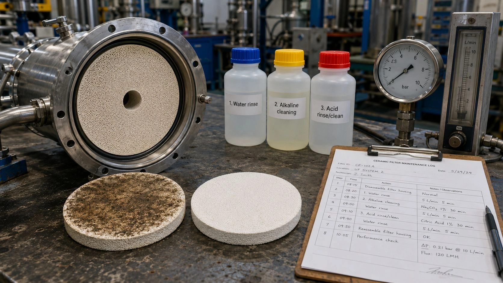
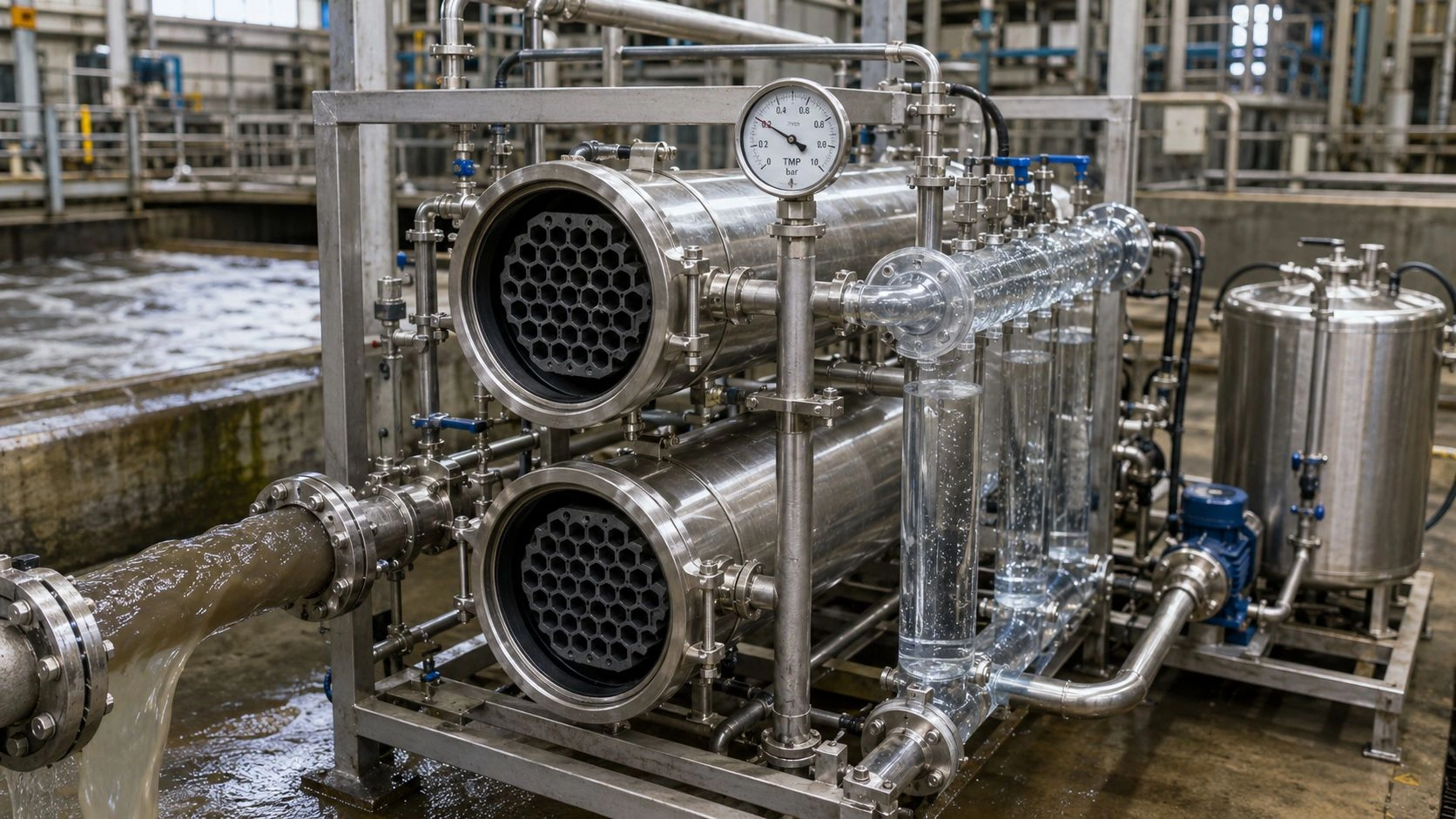
A porous ceramic plate is suitable for flow distribution when gas, vacuum, or liquid must pass evenly across a wide surface instead of escaping through a small number of large openings. Its controlled interconnected pore network creates distributed resistance, reducing channeling and localized jets by forcing the medium through many small pathways rather than concentrating through the path of least resistance. The key specifications are pore size, porosity, permeability, plate thickness, active area, allowable pressure drop, material compatibility, edge sealing design, and cleanability — not any single parameter alone.
The porous ceramics at ADCERAX — covering porous tubes, discs, plates, rods, chucks, and membrane elements in alumina, silicon carbide, zirconia, and custom ceramic materials for filtration, diffusion, flow restriction, vacuum distribution, and permeable support applications — provide the product context for the flow-distribution selection decisions described in this guide.
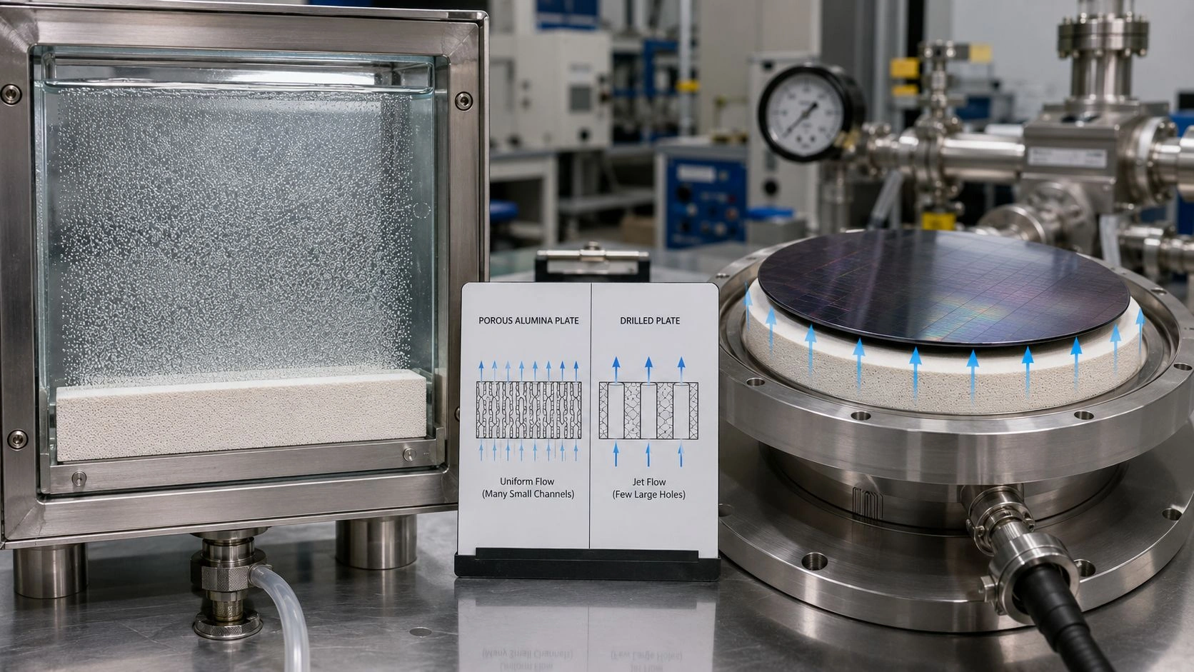
A porous ceramic plate distributes gas, vacuum, or liquid flow by creating a controlled resistance layer across its active face — the key engineering decisions are pore size, permeability, thickness, active area, pressure drop, edge sealing, and cleanability, not visual porosity alone.
How a porous ceramic plate distributes flow
A porous ceramic plate does not work like a drilled plate with fixed holes. It works as a calibrated resistance layer: the controlled interconnected pore network throughout the plate body forces the passing medium to distribute across the entire active face by creating a relatively uniform pressure drop in every path through the ceramic.
Distributed pore network versus drilled holes. When gas or liquid passes through a drilled plate, the flow concentrates through the holes and creates jets between them. The zones between holes see lower flow, and if the downstream space cannot re-mix the flow, channeling persists. A porous ceramic plate eliminates discrete holes in favor of a continuous pore network distributed throughout the ceramic body. Instead of discrete jets, the flow emerges as a uniform field across the active face. ADCERAX describes porous ceramics as materials with controlled interconnected pores that allow fluid or gas to pass through predictably, enabling filtration, diffusion, flow-restriction, and permeable-support functions.
Flow resistance as a uniformity tool. The porous plate's resistance to flow is the mechanism that creates uniformity. If the plate's permeability is low enough relative to the manifold pressure, local pressure variations across the upstream face become a small fraction of the total pressure drop through the plate, and the flow distributes more uniformly. This is the same principle described in porous-media flow theory: volumetric flow through a porous medium relates to permeability, active area, differential pressure, fluid viscosity, and flow-path length through Darcy's law — where all these variables interact to determine how easily the medium passes through. NIST's porous-media reference confirms that porous-media flow is typically characterized with a permeability parameter and modeled by Darcy-type relationships.
Gas, liquid, and vacuum distribution use cases. In gas diffusion applications — aerator plates, sparger plates, controlled atmosphere distribution, or gas introduction into reactors — the porous ceramic plate creates uniform bubbles or a distributed gas curtain across its active face. In liquid distribution, the plate creates a uniform wetting front or flow field. In vacuum distribution — vacuum chucks, fixture holders, or distributed suction tables — the porous plate distributes suction evenly across the held workpiece or surface, preventing localized suction zones that would distort or damage the workpiece.
When to choose a porous ceramic plate instead of a drilled plate or mesh
After understanding the flow mechanism, the application decision can be made: a porous ceramic plate is the right component when smooth distribution, controlled permeability, chemical or thermal resistance, and a rigid cleanable surface are all required.
Choose a porous ceramic plate when flow must spread across a wide face. When the downstream process requires uniform gas coverage, even liquid wetting, or uniform vacuum hold-down across a plate or substrate, a porous ceramic plate provides a controllable resistance layer that a drilled plate cannot replicate. ADCERAX's ceramic plate documentation confirms that porous ceramic plates deliver controlled permeability across a wide face, helping distribute vacuum or airflow evenly and reduce channeling.
Choose it when the medium is chemically aggressive, hot, or cleaning-intensive. Porous ceramic plates in alumina, silicon carbide, or zirconia tolerate temperatures and chemical cleaning conditions that would degrade polymeric diffusers, porous plastics, or sintered metal plates. For high-temperature gas distribution, corrosive chemical processes, or applications that require repeated backflush or aggressive chemical cleaning, ceramic porous plates provide a structural and chemical stability that few alternative materials match.
Avoid it when open high-flow passage is the only goal. When the system needs maximum flow with minimum resistance and flow uniformity is not the primary concern, a drilled plate, perforated screen, or open manifold may be simpler and more appropriate. Adding porous ceramic resistance creates pressure drop that must be provided by the upstream fan, pump, or pressure source — which adds energy cost if the resistance provides no distribution benefit.
Avoid it when fouling cannot be controlled. A very fine pore size in a porous ceramic plate is effective for tight distribution control, but it is also more susceptible to plugging when the medium carries particles, scale, or biological material. If fouling cannot be controlled through pretreatment or regular cleaning, the distribution quality will degrade as the plate clogs unevenly.
The Porous Ceramic Plate Flow-Distribution Selection Matrix maps the key application scenarios:
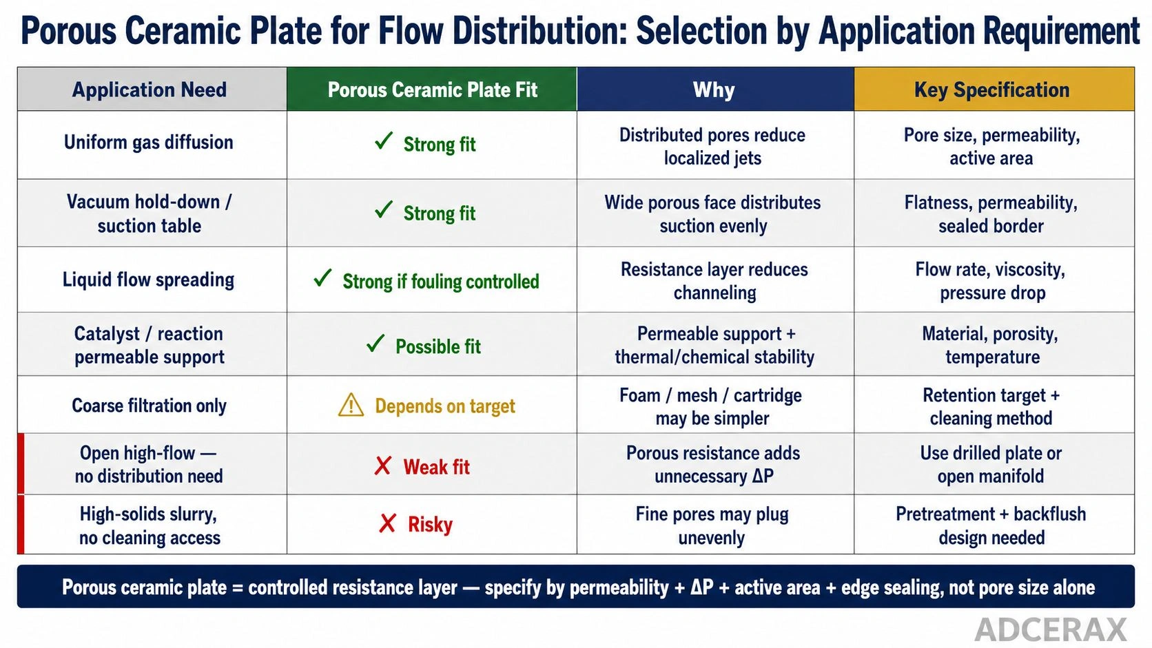
Porous ceramic plates are strongest for uniform gas diffusion, vacuum hold-down, and controlled liquid flow spreading when fouling is controlled; open high-flow systems or high-solids slurry without cleaning access may require drilled plates, manifolds, or different filtration formats instead.
| Application need | Porous ceramic plate fit | Why | Key specification |
|---|---|---|---|
| Uniform gas diffusion | Strong fit | Distributed pores reduce localized jets | Pore size, permeability, active area |
| Vacuum hold-down | Strong fit | Wide porous face helps distribute suction | Flatness, permeability, sealed border |
| Liquid flow spreading | Strong fit if fouling controlled | Resistance layer reduces channeling | Flow rate, viscosity, pressure drop |
| Catalyst/reaction support | Possible fit | Permeable support with thermal/chemical stability | Material, porosity, temperature |
| Coarse filtration only | Depends | Foam, mesh, or cartridge may be simpler | Retention target and cleaning method |
| Open high-flow passage | Weak fit | Porous resistance adds unnecessary pressure drop | Use drilled plate or open manifold |
| High-solids slurry without cleaning access | Risky | Fine pores may clog | Pretreatment and backflush design |
The numbered decision rule for quick reference:
- Choose a porous ceramic plate when flow must spread across a wide face without discrete jets.
- Choose it when channeling or localized suction zones must be reduced.
- Choose it when the medium is hot, chemically aggressive, abrasive, or cleaning-intensive.
- Choose it when a rigid, non-polymeric diffuser or permeable support is required.
- Do not choose it based on pore size alone — verify permeability, thickness, pressure drop, sealing, and cleanability.
- Do not use it as a substitute for poor manifold design or uncontrolled fouling.
Specifications that control flow uniformity and pressure drop
After confirming the application fit, the specifications that control actual distribution quality and system performance must be defined quantitatively.
Pore size: retention and clogging tendency. Nominal pore size determines the smallest particles the plate retains and how finely the flow is subdivided at the downstream face. Porex's published guidance on pore-size selection confirms the core trade-off: larger pore sizes typically provide higher flow and lower pressure drop, while smaller pore sizes improve particle retention but increase resistance and clogging risk. For flow distribution where retention is not the primary goal, pore size should be selected for the required bubble size, distribution fineness, or flow uniformity — not for maximum filtration.
Porosity and permeability: practical flow capacity. Porosity describes the fraction of void volume available for flow, but permeability — the actual ease with which fluid passes through the interconnected pore network under pressure — is the more useful engineering parameter. Two plates with identical nominal pore size may have significantly different permeability if their pore connectivity, tortuosity, or porosity differs. Mott's porous alumina documentation confirms that porous ceramic components can be engineered with tunable porosity and pore size to meet specific flow requirements, which is why permeability should be specified as a target flow rate at a defined pressure drop rather than as a material-property percentage alone.
Plate thickness: flow path and strength. A thicker porous ceramic plate provides a longer flow path, which increases pressure drop for the same pore structure but also improves structural strength, distribution stability, and resistance to pressure pulsation. A thinner plate has lower resistance but may be more susceptible to cracking during handling, thermal cycling, or clamping stress. The thickness selection must balance flow resistance, mechanical integrity, and edge-sealing compressibility.
Active area and edge sealing. The active porous area — the zone through which flow actually passes — must be clearly defined and sealed at the border to prevent bypass. If gas, liquid, or vacuum can find a path around the porous structure through a poorly sealed edge, the distribution quality is compromised regardless of how well the plate itself is specified. Edge design — sealed border width, gasket groove, adhesive bond, or press-fit into a housing — is a critical part of the plate specification.
The Specification Matrix maps the variables:
| Specification | What it controls | Wrong-spec risk | RFQ requirement |
|---|---|---|---|
| Pore size | Retention, bubble size, clogging tendency | Too fine = high ΔP; too coarse = poor distribution | Nominal pore size or pore-size range |
| Porosity | Available flow pathways | High porosity may reduce strength; low may restrict flow | Porosity target or supplier range |
| Permeability | Actual flow at pressure | Same pore size may flow differently by microstructure | Flow rate at defined pressure and medium |
| Thickness | Flow path length and strength | Too thin = weak/jetting; too thick = high pressure drop | Plate thickness + tolerance |
| Active area | Distribution coverage | Edge bypass or dead zones | Active porous area and sealed border |
| Material | Temperature, chemistry, cleaning | Chemical attack, thermal cracking, contamination | Alumina/SiC/zirconia/other |
| Flatness | Contact, sealing, uniform gap | Leakage, uneven compression | Flatness tolerance |
| Cleaning method | Recovery after fouling | Permanent plugging or damage | Backflush/ultrasonic/chemical compatibility |
Values indicative; verify with supplier-specific flow testing and application data.
The ceramic plate page covers the porous and dense ceramic plate product range, including vacuum distribution, flow-control, wear, and high-temperature plate applications. The microporous alumina plate page covers porous alumina plate specifications including disc and sheet geometries for vacuum, diffusion, and filtration.
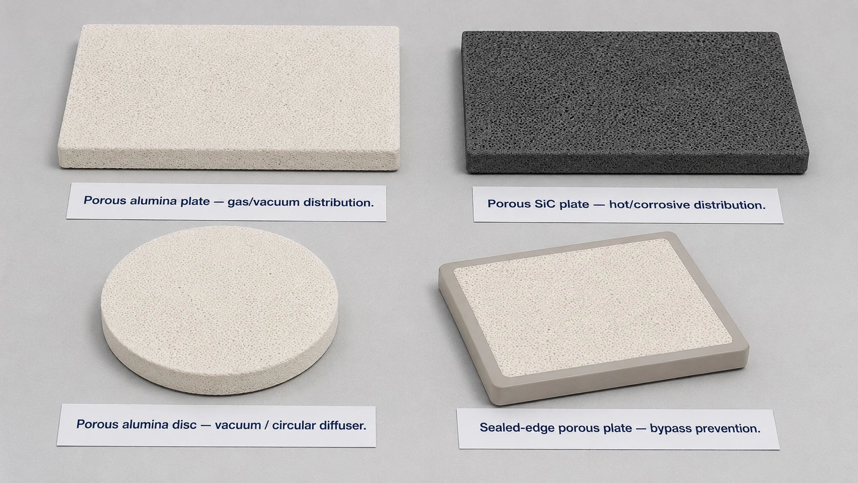
Porous ceramic flow-distribution plates may use alumina for general gas or vacuum distribution, SiC for hot or corrosive distribution, circular discs for diffuser layouts, and sealed-edge plate designs when bypass prevention is critical.
Common mistakes that cause channeling, uneven flow, or excessive pressure drop
Many flow-distribution problems in systems using porous ceramic plates originate in design or specification errors rather than material quality issues.
Mistake 1: specifying pore size but not permeability. A plate with a 10 µm nominal pore size from one supplier may have a very different actual flow rate than a 10 µm plate from another supplier if the pore connectivity, porosity, or manufacturing route differs. The correct specification request is a flow rate at a defined pressure drop and fluid viscosity — not just a pore-size label.
Mistake 2: ignoring edge sealing and bypass flow. An unsealed edge allows flow to take the path of least resistance around the porous structure rather than through it. Even a small gap between the plate and its housing seat can create significant bypass that undermines distribution uniformity. Edge sealing — whether through a compressed gasket, adhesive bond, or precision mechanical fit — is as important as the plate specification itself.
Mistake 3: using filtration-grade pores for a distribution-only job. When the application only needs flow distribution without particle retention, specifying the finest available pore size adds unnecessary pressure drop and increases clogging risk from the very small particles that would never cause a problem in a coarser structure. Match the pore size to the required distribution fineness, not to the maximum filtration achievable.
Mistake 4: blaming the plate when the manifold is uneven. If the upstream manifold delivers uneven pressure across the plate inlet face, even a perfectly uniform porous plate cannot fully compensate. The plate's distribution quality assumes reasonably uniform upstream pressure. When manifold design is poor, the plate appears to channel, but the root cause is the manifold.
Mistake 5: ignoring cleaning access and fouling recovery. A porous ceramic plate that cannot be backflushed, soaked, or ultrasonically cleaned after fouling will lose its distribution quality over time as pores clog unevenly. The cleaning protocol must be defined before the plate is specified, not after fouling has occurred.
What to include in an RFQ for porous ceramic flow-distribution plates
The RFQ Checklist maps the required information for a flow-distribution plate specification:
| RFQ item | Why it matters |
|---|---|
| Medium | Gas, liquid, vacuum, solvent, hot gas, or slurry changes flow behavior |
| Flow rate | Defines required permeability and active area |
| Pressure range | Determines pressure-drop and strength requirements |
| Allowable pressure drop | Prevents undersized or overly fine plate selection |
| Pore size | Controls distribution, bubble size, retention, and clogging tendency |
| Porosity/permeability | Determines practical flow capacity at operating conditions |
| Plate thickness | Affects strength and pressure loss |
| Active area | Determines distribution coverage |
| Edge sealing | Prevents bypass and channeling |
| Material | Determines chemical, thermal, and cleaning compatibility |
| Flatness | Critical for gasket sealing and uniform compression |
| Cleaning method | Determines recoverability after fouling |
| Drawing | Confirms holes, grooves, mounting, border, and tolerance zones |
For gas distribution applications, include gas type, flow range, supply pressure, maximum backpressure, and whether bubble size uniformity or jet suppression is the performance target. For vacuum distribution, include vacuum level, required hold force per unit area, and whether the plate contacts a workpiece directly. For liquid distribution, include fluid viscosity, solids content, fouling risk, chemical composition, and cleaning frequency.
The most useful supplier request is not ""quote a porous plate"" but ""quote a porous plate that delivers this flow at this pressure over this active area under these operating conditions, with this material, this cleaning protocol, and these dimensional tolerances.""
Specifying a porous ceramic plate for flow distribution? Share your drawing, medium, required flow rate, operating pressure range, allowable pressure drop, active area, pore-size target, temperature, chemistry, cleaning method, and mounting configuration. ADCERAX can review material, pore size, thickness, and permeability options and provide a sample plate for flow testing before final order.
Frequently Asked Questions
What is a porous ceramic plate used for in flow distribution?
It is used to spread gas, liquid, or vacuum evenly across a wide surface using a controlled interconnected pore network. The distributed resistance of the porous structure helps reduce localized jets, uneven suction, and channeling compared with systems using drilled holes or discrete openings.
How does a porous ceramic plate improve flow uniformity?
By adding distributed resistance across the active face. That resistance forces the medium to pass through many small pore pathways instead of concentrating through the easiest open channel, which is the mechanism that suppresses channeling and distributes flow more uniformly.
Is pore size the most important specification?
Pore size is important, but it is not sufficient alone. Flow distribution also depends on porosity, permeability, plate thickness, active area, pressure drop, edge sealing, and fluid viscosity. Two plates with identical nominal pore size may behave very differently if microstructure, porosity, or thickness differs — which is why permeability at a defined pressure should be specified alongside pore size.
Should I choose alumina, SiC, or zirconia for porous ceramic plates?
Alumina is often used for stable insulation, standard diffusion, and general-purpose porous ceramic plates. Silicon carbide is better suited for harsh, hot, abrasive, or chemically demanding flow conditions. Zirconia may be considered when mechanical toughness or specific chemical compatibility is needed. The final choice depends on operating temperature, chemical exposure, cleaning protocol, and mechanical load.
Why does pressure drop matter for flow distribution?
Pressure drop determines whether the upstream system can deliver the required flow through the plate at the operating pressure. If resistance is too high, the required flow cannot be achieved. If resistance is too low, the plate provides insufficient equalization and distribution becomes dependent on manifold uniformity rather than the porous structure.
What causes channeling in porous ceramic flow distributors?
Common causes include uneven upstream manifold pressure, edge leakage around unsealed borders, poor gasket compression, nonuniform porous structure, overly coarse pores for the distribution requirement, progressive fouling, or specifying pore size without verifying permeability. The root cause may be in the manifold or sealing design rather than the plate itself.
What should I include in an RFQ for a porous ceramic flow-distribution plate?
Include medium type, flow rate, pressure range, allowable pressure drop, target pore size, permeability or flow-rate target, porosity, plate thickness, active area, sealed border design, material, dimensions and tolerances, flatness, mounting method, temperature, chemistry, and cleaning protocol. A drawing is strongly recommended.
"