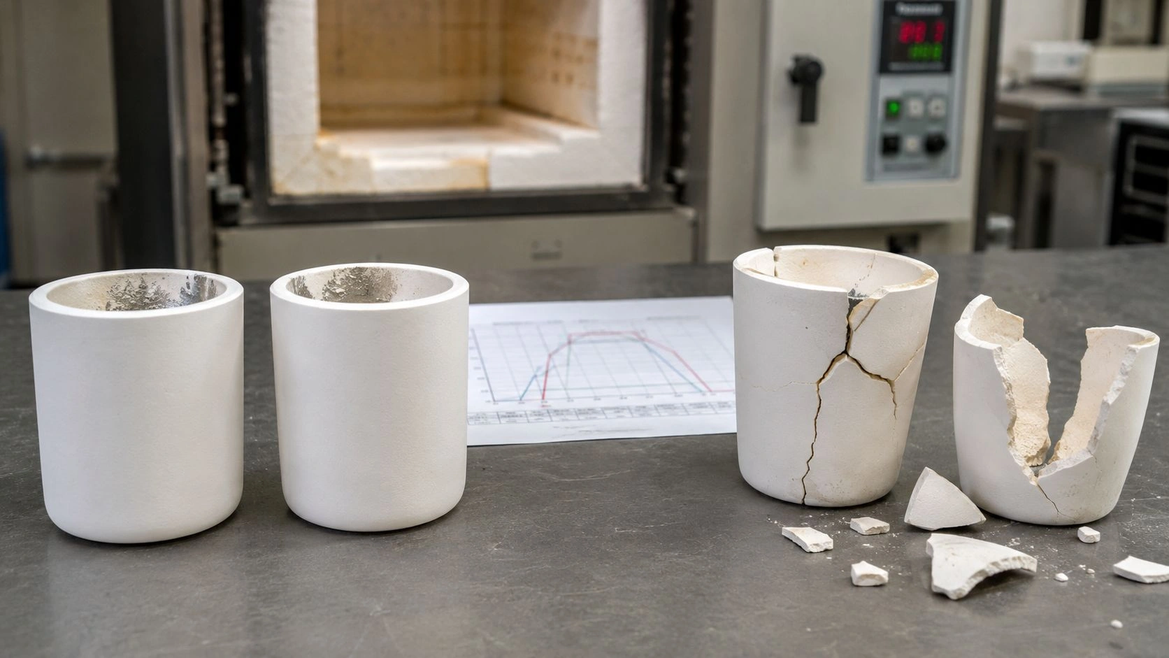
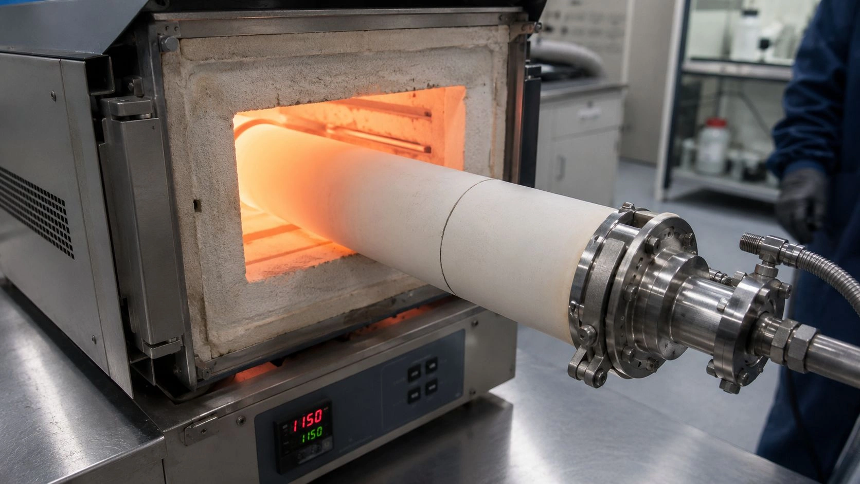
A cracked alumina tube in a tube furnace is not a single problem. It is a category of problems, and each category points toward a different corrective action. The maintenance manager who re-orders the same tube after a radial hot-zone fracture and the process engineer who blames the supplier after an end-seal crack are both likely to repeat the failure — because the tube is only one variable in a system that also includes ramp rate, support span, end constraint, sample chemistry, atmosphere, and load. This article converts visible failure signatures into root-cause diagnoses, clarifies the misreadings that generate unnecessary repeat failures, defines the prevention thresholds that actually reduce recurrence, and closes with the replacement RFQ structure that gives a supplier enough information to help rather than simply ship the same size again.
Alumina tubes in tube furnaces most often fail from thermal shock, axial temperature gradients, constrained expansion, inadequate horizontal support, sample moisture, chemical attack, excessive sample load, or prolonged high-temperature exposure. Crack location is the primary diagnostic clue: mid-zone radial cracks suggest thermal shock, end fractures suggest constraint, sagging indicates creep or support error, and surface roughening points to chemical incompatibility. Replacement should be specified from the confirmed failure mode, not from tube dimensions alone.
Crack location is the first diagnostic variable — where the fracture begins on the tube places it in one of the 12 failure cases.
The alumina tube family for tube-furnace service — spanning thermocouple protection tubes, sensor sleeves, heating-element liners, and process tubes rated to 1700°C — is the broader product context that this article's diagnostic and RFQ logic connects to directly.
What the 12 common alumina tube failure cases look like
Maintenance teams usually start with the failed part in hand. The table below classifies 12 visible failure signatures into root-cause families, diagnostic clues, and first corrective actions. ASTM C1322 supports this diagnostic approach by treating fracture-origin characterization as a structured, evidence-based practice for advanced ceramics rather than an assumption-based judgment — meaning crack location, surface features, and run history should all be collected before any root cause is assigned.
The twelve cases, organized by visible presentation:
- Radial crack through the hot zone — appears after fast ramping or cooling; primary cause is thermal shock; reduce ramp and cooling speed, verify sample temperature equilibration before insertion.
- Longitudinal crack along tube length — crack follows a wall section unevenly heated or cooled; primary cause is wall temperature gradient from non-uniform heating or eccentric sample placement.
- End fracture near seal, clamp, or flange — crack initiates at or near the constrained end; primary cause is constrained axial expansion during thermal cycling; allow free axial movement, check alignment and gasket compression.
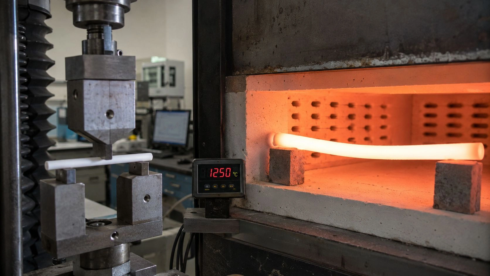
- Tube sagging in horizontal orientation — tube bends downward during or after long high-temperature run; primary cause is high-temperature creep under self-weight or process load across an unsupported span.
- Local fracture directly beneath sample boat — crack localizes below the boat contact line; primary cause is point loading or inadequate boat support distribution.
- Cracking after loading cold or wet samples — failure follows a batch containing moisture-bearing samples or boats; primary cause is rapid steam vaporization and local thermal transient.
- Ring crack near hot-zone boundary — circumferential crack forms at the transition between hot zone and cold zone; primary cause is sharp axial temperature gradient creating hoop-stress concentration.
- Surface roughening or wall thinning on inner wall — inner surface appears etched, glazed, or discolored; primary cause is chemical vapor, alkali flux, reactive atmosphere, or sample deposit interaction.
- Deposit-bonded fracture — crack initiates at a location where sample residue or reaction product has bonded to the wall; primary cause is sample–ceramic reaction or improper cleaning protocol.
- Leak without full break — vacuum or atmosphere control is lost while tube appears intact; primary cause is microcrack propagation from prior thermal cycling, handling, or installation impact.
- End chipping on installation or removal — fresh chip at end face; primary cause is handling or installation impact; chip edge becomes a stress-concentration site for future thermal cycles.
- Short service life under apparently correct SOP — tube fails repeatedly without obvious cause; primary cause is purity mismatch, insufficient wall thickness, inadequate density, or a manufacturing flaw not caught by incoming inspection.
| Case | Visible failure | Likely root cause | Diagnostic clue | First corrective action |
|---|---|---|---|---|
| 1 | Radial crack, hot zone | Thermal shock | Crack after fast ramp or cooling | Slow ramp and cooling; check sample pre-heat |
| 2 | Longitudinal crack | Wall temperature gradient | Crack follows tube length | Improve heating uniformity; reposition sample |
| 3 | End fracture near seal | Constrained expansion | Crack at clamp / flange / gasket | Allow axial expansion; check alignment |
| 4 | Tube sagging | High-T creep / support span | Tube bends in horizontal use | Reduce span and load; increase wall thickness |
| 5 | Local fracture under boat | Point loading | Crack below sample boat | Use distributed support; reduce load |
| 6 | Crack after wet samples | Steam pressure / thermal transient | Failure follows moisture-rich batch | Pre-dry samples and boats |
| 7 | Ring crack, hot-zone boundary | Axial temperature gradient | Crack at transition zone | Reduce gradient; reposition supports |
| 8 | Surface roughening | Chemical vapor or flux attack | Inner wall etched or glazed | Review sample chemistry and atmosphere |
| 9 | Deposit-bonded fracture | Sample reaction or sticking | Crack below bonded residue | Change boat material or cleaning method |
| 10 | Leak without full break | Microcrack propagation | Atmosphere/vacuum loss before visible break | Inspect with light/pressure; replace tube |
| 11 | End chipping | Handling or installation impact | Fresh chip at end face | Improve packaging and installation practice |
| 12 | Short life despite correct SOP | Material or spec mismatch | Repeats under normal operation | Review purity, wall thickness, density, and inspection records |
Values indicative; verify with supplier-specific operating limits, furnace manual, and actual service testing.
For context on how alumina tubes are positioned within the broader family of high-temperature furnace components, industrial furnace ceramics covers the wider hardware ecosystem that replacement-tube decisions often connect to.
What root mechanisms cause alumina tubes to fail
Most alumina tube failures arise from stress gradients rather than a simple loss of temperature resistance. Understanding the mechanism behind each case group changes both the corrective action and the RFQ for the replacement tube.
Thermal mechanisms account for the largest share of tube failures in laboratory and industrial tube furnaces. Thermal shock occurs when heating or cooling creates a temperature difference across the tube wall fast enough that the hotter side expands while the cooler side is still constrained, generating tensile stress. ASTM C1525 evaluates thermal-shock resistance by heating specimens, then quenching them rapidly and measuring retained flexural strength — a methodology directly relevant to interpreting crack patterns that follow temperature changes rather than simple overload. The hot-zone boundary ring crack (Case 7) is a related phenomenon: the axial temperature gradient between the hot zone and the cooler flange zone creates a stress concentration at the transition even when the ramp rate is moderate. Sample moisture adds a third thermal pathway: water absorbed by samples or ceramic boats vaporizes rapidly during heat-up, creating a local pressure and thermal transient that can crack the tube at the contact zone.
Mechanical and creep mechanisms govern sagging, end fractures, and load failures. High-temperature creep in alumina follows from sustained stress at temperatures approaching the practical service limit; ASTM C1291 covers tensile creep strain, creep rate, and time-to-failure for advanced monolithic ceramics over the 1073–2073 K range, providing a framework for understanding why long-span horizontal tubes under load deform progressively. End-constraint fractures occur when both ends of the tube are rigidly fixed while the tube expands axially during heat-up — the expansion energy is redirected into bending or shear at the seal, producing a characteristic end-region crack rather than a mid-zone fracture. Point loading under sample boats creates a similar local stress concentration when the boat contacts the tube on a narrow line.
Chemical and surface mechanisms are the most commonly underdiagnosed failure family. Alkali vapors, low-melting-point flux species, reactive atmospheres, and sample residues that bond to the alumina inner wall attack grain-boundary phases and generate stress concentrations at the contamination front. Reducing atmospheres containing hydrogen require compatibility confirmation against the alumina grade's secondary phases, and some grades show grain-boundary attack in repeated exposure at high temperature and low oxygen partial pressure.
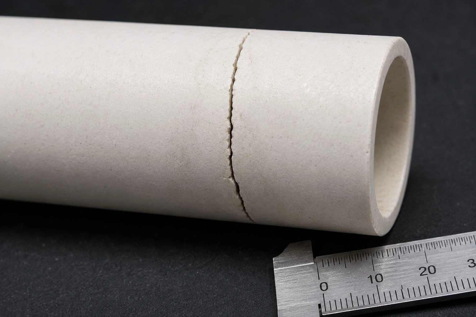
A circumferential ring crack at the hot-zone boundary is a characteristic signature of axial thermal gradient stress — distinct from the radial cracks of fast-cooling thermal shock.
How to avoid misdiagnosing alumina tube failure
The most costly misread in tube furnace maintenance is assigning supplier blame to a tube that failed for a process reason. That misread produces a new tube order with the same specification running in the same furnace with the same SOP — and the same failure four to eight weeks later.
ASTM C1322 establishes that fracture-origin characterization in advanced ceramics requires structured evidence collection: crack location, fracture surface features, operating history, and microstructural information should all inform the diagnosis rather than a single visual impression. A disciplined diagnostic pass before assigning cause requires less time than a repeated tube replacement cycle.
The misdiagnosis matrix below converts the most common symptom–blame pairings into the more productive evidence question:
| Symptom | Often blamed on | More likely cause to check first | Evidence needed |
|---|---|---|---|
| Tube cracked after cooling | Poor tube quality | Thermal shock or forced cooling | Cooling profile, door-opening history |
| Crack near end seal | Brittle ceramic | End constraint or misalignment | Seal design, clamp load, expansion allowance |
| Sagging tube | Material weakness | Span, wall thickness, load, high-T exposure | Tube geometry, support distance, operating hours |
| Rough inner wall | Normal aging | Chemical attack or sample deposits | Sample chemistry, atmosphere, cleaning record |
| Repeated short life | Bad supplier | Wrong grade, wall, support, or SOP mismatch | Full RFQ, photos, batch records |
| Leak before visible fracture | Random failure | Microcrack from handling or thermal cycling | Installation record, leak-test history |
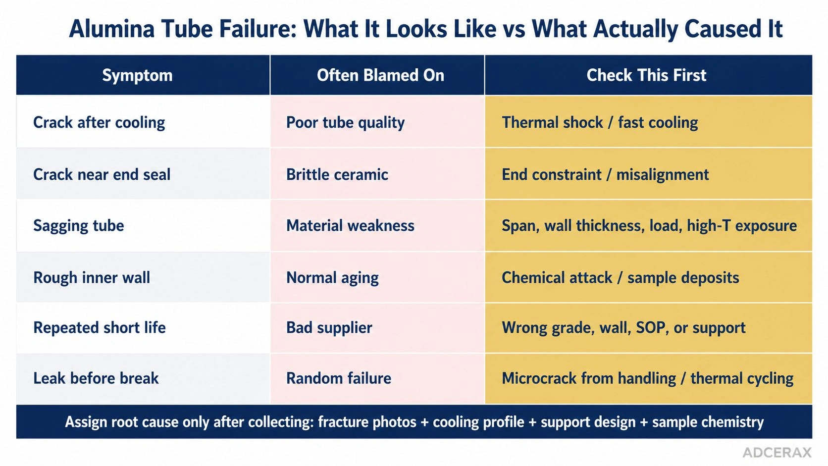
The misdiagnosis matrix guides evidence collection before assigning root cause — the same crack appearance can arise from different mechanisms requiring different corrective actions.
A specification review for a thermocouple protection tube or process tube in a tube furnace that has experienced repeated failures typically begins by separating three questions before the replacement order is placed: Was the SOP followed correctly? Did the process or support design create the stress? Was the tube specification matched to the actual service condition? Only after those questions are answered does supplier quality become the primary variable.
The most common misdiagnosis pattern is reading a radial hot-zone crack as a tube-quality failure and ordering a replacement without adjusting the ramp rate or cooling protocol. The crack reappears in the same location after the same number of thermal cycles. The second most common pattern is attributing end-seal fractures to brittleness and ordering a thicker-wall tube — without changing the rigid end mount that created the expansion constraint. Thicker wall changes the stress distribution but does not eliminate the constraint-driven load.
If the furnace SOP and support design haven't changed and the new tube fails in the same location, the diagnosis was wrong.
For teams evaluating whether the current tube grade is matched to the process, sending failure photos to the supplier for review before reordering takes the diagnosis out of assumption and into evidence. A supplier who reviews fracture photos before recommending a replacement is more likely to flag a spec mismatch than one who re-ships the same part number.
What prevention thresholds and tube specifications reduce recurrence
Prevention should target the confirmed failure mode. Applying the wrong prevention measure — such as specifying a thicker wall for a thermal-shock failure — spends budget without reducing the relevant stress. The controls below are organized by failure family.
Operating controls
For thermal shock, limit ramp and cooling rates to a level the furnace and tube combination can sustain without creating damaging wall temperature gradients. Published furnace maintenance guidance cites 60°C per hour as a conservative starting ramp limit for ceramic tubes; the appropriate rate depends on furnace design, tube wall thickness, hot-zone length, and sample mass, so the supplier's recommended limit for the specific tube should be confirmed. Avoid opening furnace doors rapidly at operating temperature, avoid directing room-temperature air onto a hot tube section, and pre-dry samples and boats at 120°C or appropriate temperature before insertion.
For end fractures, mount the tube free to expand axially at one end, and use a slip-fit or compliant seal rather than a rigidly clamped flange at both ends. The same furnace guidance source explicitly recommends securing only one end tightly and allowing the other to float. Check that the tube is straight, that the bore axis aligns with the furnace bore, and that any sealing gasket does not apply uneven compressive load.
For sagging, reduce the unsupported span, reduce sample boat weight, and verify that the tube wall thickness is specified for long-span horizontal service at the operating temperature. Wall-thickness selection for creep-limited horizontal service is not the same calculation as wall-thickness selection for pressure containment.
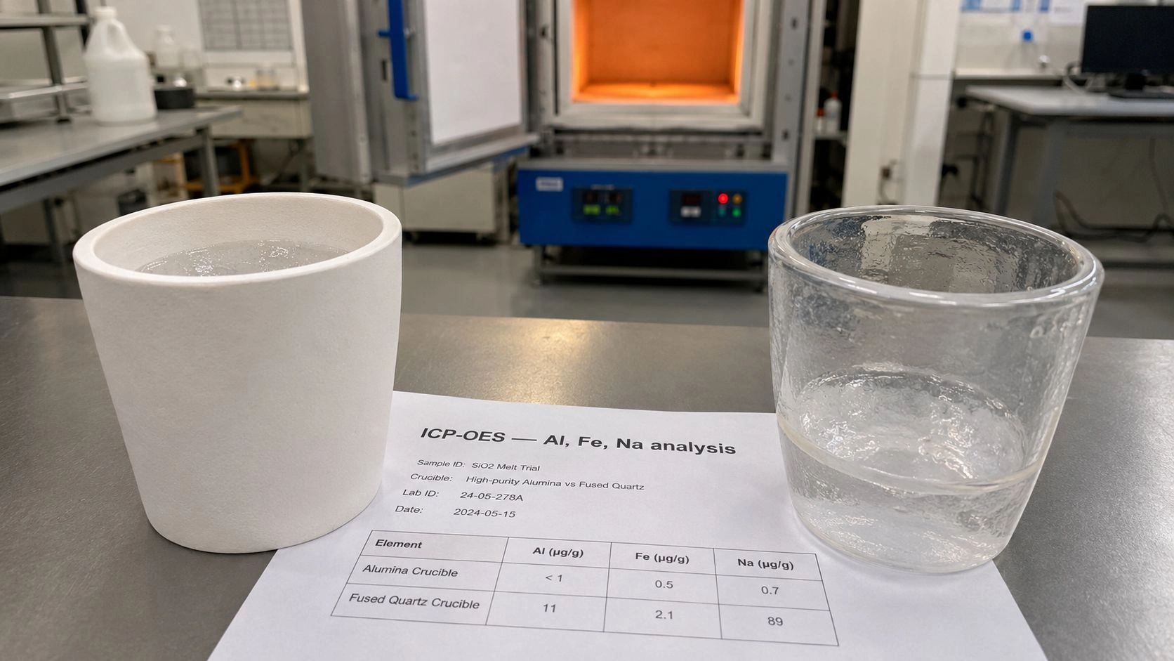
For chemical attack, define the atmosphere, sample vapor species, flux composition, and cleaning method in the tube specification before ordering. Alumina purity affects grain-boundary phase chemistry; a 99.5% Al₂O₃ tube and a 99.8% Al₂O₃ tube behave differently in atmospheres containing alkali vapors or at high temperature with reactive samples.
Replacement tube specification controls
| Failure mode | Operating control | Tube specification control | Supplier data to request |
|---|---|---|---|
| Thermal shock | Slow ramp and cooling; no forced air cooling | Wall thickness; grade appropriate for ramp window | Thermal-shock guidance or test basis |
| End fracture | One-end-fixed or float mount; check alignment | End geometry, length tolerance, straightness | Installation notes and dimensional report |
| Sagging | Shorter unsupported span; lower load | Larger wall; support-ready geometry | High-temperature creep guidance |
| Chemical attack | Define vapors, flux, atmosphere, cleaning | Higher purity or compatible grade | Material composition and compatibility notes |
| Sample-load fracture | Distributed boat support; reduce load | OD/ID/wall for load geometry | Drawing review and load comment |
| Microcrack/leak | Gentle handling; incoming inspection | Surface finish; packaging; final QC | Photos, packing method, QC record |
For purity, microstructure, and long-term reliability selection across alumina tube grades for high-temperature furnace service, the alumina ceramic tube selection overview provides the grade-by-grade compatibility context that this prevention logic connects to.
What a replacement alumina tube RFQ should require after failure
A replacement order placed without failure context produces a tube that fits the furnace bore but may not address the failure mode. The RFQ should contain two blocks: one documenting the failed tube and its service history, and one specifying the replacement.
Failed-tube documentation block
- Photographs of the fracture surface, crack location on the tube, and full tube exterior — images taken before cleaning are more diagnostic than post-cleaning images.
- Tube dimensions: OD, ID, wall thickness, total length, and hot-zone length.
- Furnace model, orientation (horizontal or vertical), support span, and end-seal design.
- Operating temperature, ramp rate, soak time, and cooling rate from the most recent failed run.
- Atmosphere: air, inert, oxidizing, reducing, or controlled — with any process gases, vapors, or fluxes.
- Sample chemistry, boat material, boat weight, and loading method.
- Number of thermal cycles completed before failure and whether failure was first occurrence or repeated.
- Any cleaning history, handling damage, or installation notes.
Replacement tube specification block
- Required alumina purity, with trace element limits where sample contamination is a concern.
- OD, ID, wall thickness, and length — with tolerances on straightness, concentricity, and end-face squareness.
- End style: plain, beveled, closed-end, or machined flange as needed for the seal design.
- Surface finish on inner wall if deposit adhesion or cleaning frequency is a design driver.
- Maximum operating temperature and required service life at that temperature.
- Atmosphere compatibility confirmation for the specific gas species.
- Density, porosity, or flexural-strength minimums if dimensional stability and creep resistance are critical.
- Packaging requirements: individual wrapping, anti-vibration support, and inspection confirmation.
- Supplier-provided installation guidance, recommended ramp limit, and support-span recommendation for the specific tube geometry.
For the broader replacement-tube materials decision — including whether alumina, silicon carbide, zirconia, or another ceramic is the right material for the next service window — the ceramic tubes comparison provides the cross-material routing context that post-failure grade reviews often require.
Conclusion
Alumina tube failure in a tube furnace is a systems diagnosis, not a parts quality call. The crack location tells you where the stress exceeded fracture strength; the operating history tells you why the stress reached that level; the SOP, support design, and sample chemistry tell you whether the same failure will recur. Thermal shock, end constraint, span and load, sample moisture, and chemical attack each require a different corrective action — and each requires a different replacement specification. An RFQ written from a confirmed failure mode produces a tube that fits the service. An RFQ written from tube dimensions alone repeats the cycle. The twelve cases in this article are organized so that the failed tube in hand maps to a root cause and a corrective action, rather than to a simple reorder.
Investigating a cracked, sagged, or short-lived alumina tube in a tube furnace? Send the fracture photographs, furnace temperature profile, tube dimensions, support span, end-seal design, atmosphere, and sample chemistry. ADCERAX engineers return a root-cause assessment with replacement tube recommendation, specification notes, and installation guidance for the confirmed failure mode; turnaround depends on evidence quality and inquiry complexity.
Frequently Asked Questions
Why do alumina tubes crack in tube furnaces?
Alumina tubes typically crack because thermal gradients, rapid heating or cooling, end constraint, sample moisture, mechanical load, or chemical attack generate tensile stress beyond the tube's fracture strength. The crack location is the first diagnostic clue: mid-zone radial cracks suggest thermal shock, end-region cracks suggest expansion constraint, and ring cracks at the hot-zone boundary suggest axial temperature gradient stress.
Is every cracked alumina tube a supplier-quality problem?
No. Supplier quality matters but accounts for a minority of repeated failures in practice. Most cracks originate from ramp rate, forced cooling, unsupported span, rigid end sealing, sample moisture, heavy boat loading, or incompatible process chemistry. ASTM C1322 emphasizes structured fracture-origin analysis — collecting crack location, operating history, and tube geometry — rather than assumption-based blame assignment.
What crack pattern suggests thermal shock?
A radial or circumferential crack near the hot zone, particularly one that appears after fast cooling, door-opening, or sample insertion, often suggests thermal shock. ASTM C1525 evaluates thermal-shock resistance through retained flexural strength after rapid quenching, and the same methodology informs how crack patterns after temperature excursions should be interpreted. Fracture surface photos and the run log should both be reviewed before confirming the cause.
Why does an alumina tube sag in a horizontal furnace?
Sagging typically reflects high-temperature creep under gravity load across an unsupported span, especially after long operating hours near the tube's service limit. ASTM C1291 covers elevated-temperature tensile creep strain, creep rate, and time-to-failure for advanced monolithic ceramics and provides the framework for understanding why span, wall thickness, load, and operating temperature combine to determine whether a tube holds its shape. Reducing the unsupported span, reducing sample load, or specifying a heavier wall section are the standard corrective actions.
Can sample moisture break an alumina furnace tube?
Yes. Water absorbed by samples or ceramic boats vaporizes rapidly during heat-up, creating a local pressure transient and thermal gradient at the contact zone. This can crack the tube even when the ramp rate is otherwise controlled. Pre-drying samples and boats before furnace loading is a standard preventive step, particularly for hygroscopic materials or boats that have been stored in humid environments.
Should a cracked alumina tube be repaired?
For high-temperature, controlled-atmosphere, vacuum, or load-bearing furnace service, replacement is the safer decision. Microcracks can propagate through subsequent thermal cycles even when a crack appears localized, and structural repair of an alumina tube does not restore original strength or hermeticity. Replacement should be specified from the diagnosed failure mode, not from the crack geometry alone.
What should I send to a supplier after alumina tube failure?
Send photographs of the fracture surface and crack location before cleaning, tube OD, ID, wall thickness, and length, furnace model and orientation, support span and end-seal design, operating temperature and ramp and cooling profile, atmosphere and process gases, sample chemistry and boat weight, number of thermal cycles before failure, and any relevant installation or handling notes. Without failure photos and operating history, the supplier cannot distinguish a spec mismatch from a process error and will likely recommend the same tube.