The alarm raised when an alumina tube cracks during cathode calcination is almost always the same: the tube was rated to a temperature far above what the furnace runs, so why did it fail so early? The answer is that cathode calcination is not a single-variable duty. A tube in this service simultaneously manages oxygen flow at elevated temperature, axial temperature gradients across the hot zone, repeated thermal cycling from charge to charge, possible contact with lithium-bearing species that can react at the bore surface, and whatever expansion constraint the end seals and mounting hardware impose. Evaluating only the catalog maximum temperature against the furnace setpoint misses all of those interactions. This article classifies the failure modes that appear earliest, explains which combined-duty mechanisms accelerate each one, removes the misdiagnosis that leads to repeat purchases without root-cause correction, and closes with the specification variables and supplier data that actually change the outcome.
Alumina tubes in Li-ion cathode calcination usually fail early not because 700–900°C exceeds alumina's absolute temperature capability, but because the duty combines oxygen flow, steep axial temperature gradients, repeated thermal cycling, possible lithium-salt interaction at the bore surface, and installation restraint. The correct question is not "Can alumina survive this temperature?" but "Can this tube survive the chemistry, gradient, span, and cycle count of this calcination line?"
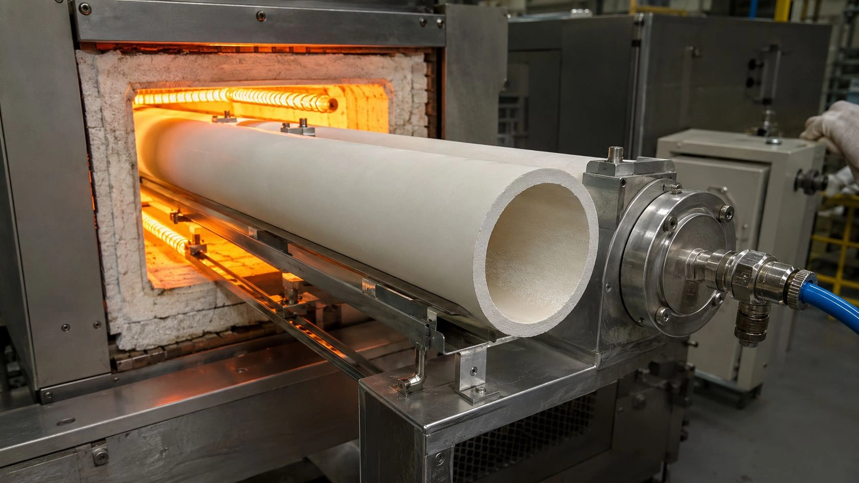
Cathode calcination is a coupled thermal-chemical duty: oxygen flow, axial gradients, lithium-bearing atmosphere, and end-constraint stress act on the alumina tube simultaneously — not in isolation.
The broader alumina furnace tubes family — grades, geometries, and service limits for high-temperature process applications — provides the procurement context that this failure-analysis and RFQ logic connects to directly.
What failure mode usually appears first in Li-ion cathode calcination alumina tubes
In cathode calcination, "alumina tube failure" is rarely one event. The first observable mode is usually one of four: longitudinal cracking after cooldown, permanent bowing or ovality before fracture, surface conversion or deposit formation on the bore wall, or end-localized cracking near seals and restraint points. Those modes do not imply the same root cause, and misclassifying them at this stage leads to corrective actions that address the wrong variable.
A tube that bows before it cracks is reporting hot-load distortion under sustained elevated-temperature stress. A tube that remains straight but develops an inner-wall reaction layer is reporting a chemical interaction at the bore surface rather than a mechanical failure. And variable cathode powder morphology across batches is not automatic evidence of tube damage at all — DOE work comparing tube and box furnaces showed that calcination route, mixing homogeneity, Li ratio, temperature profile, and oxygen atmosphere can change primary-particle morphology and lithiation uniformity independently of whether the ceramic component has structurally failed. Classifying the visible symptom correctly before assigning cause is the prerequisite for every corrective action that follows.
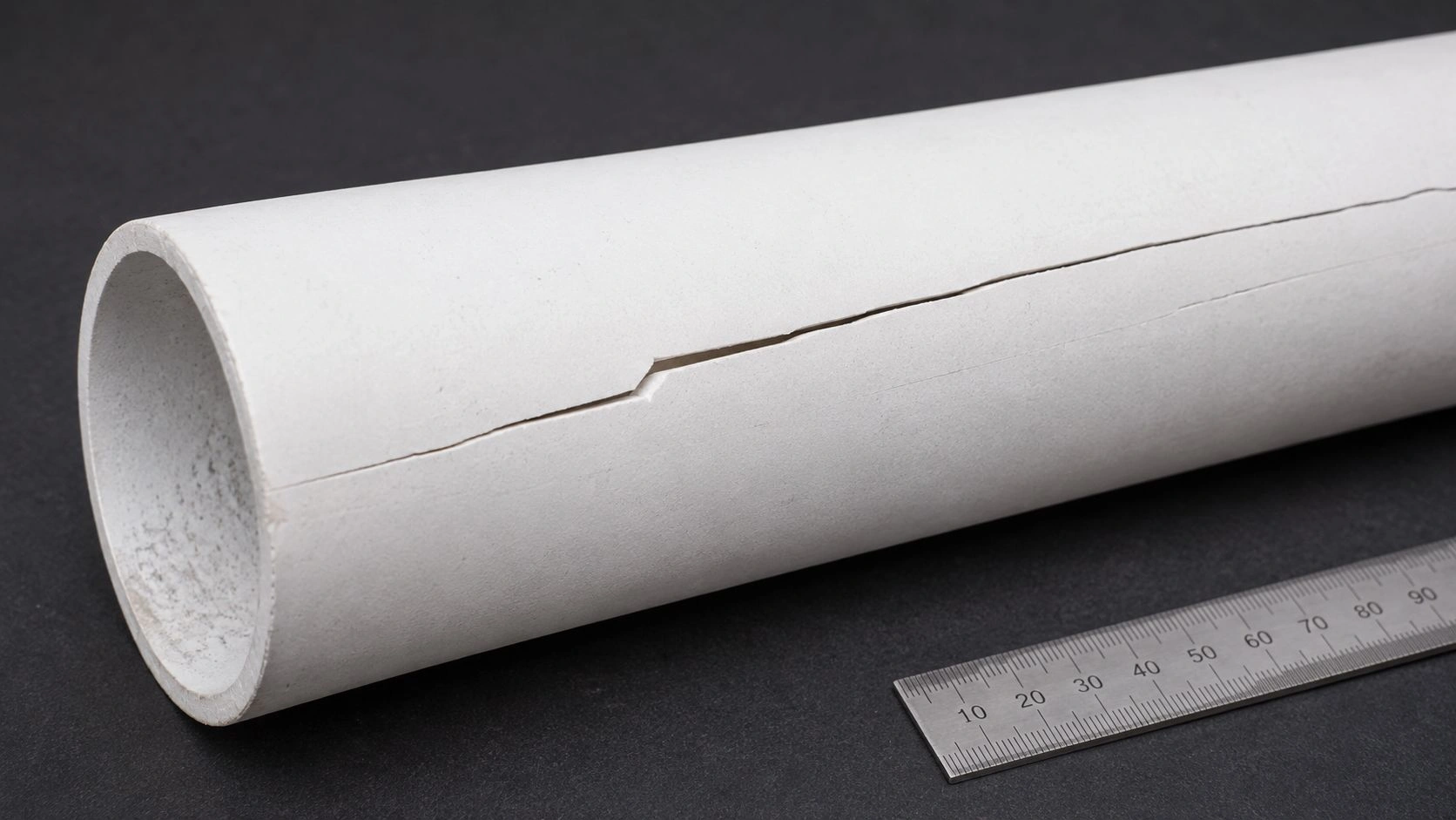
A longitudinal crack emerging after cooldown from the hot-cold transition zone of a calcination tube is a characteristic thermal-shock signature — different in origin from an end-localized crack at a restraint point.
Typical early crack signatures in hot and cold transition zones
Longitudinal cracks that develop after ramp-down, and that are spatially aligned with the boundary between the furnace hot zone and the cooler end section, are the characteristic signature of transient thermal-shock damage. The component survived the soak temperature but failed during the cooling phase because the temperature gradient across the ceramic wall exceeded what the material's thermal-shock resistance could sustain. That is a transient-condition failure, not a maximum-temperature failure, which is why evaluating it requires transient-condition test logic rather than catalog soak-temperature comparison.
What "bowing before cracking" means in ceramic service
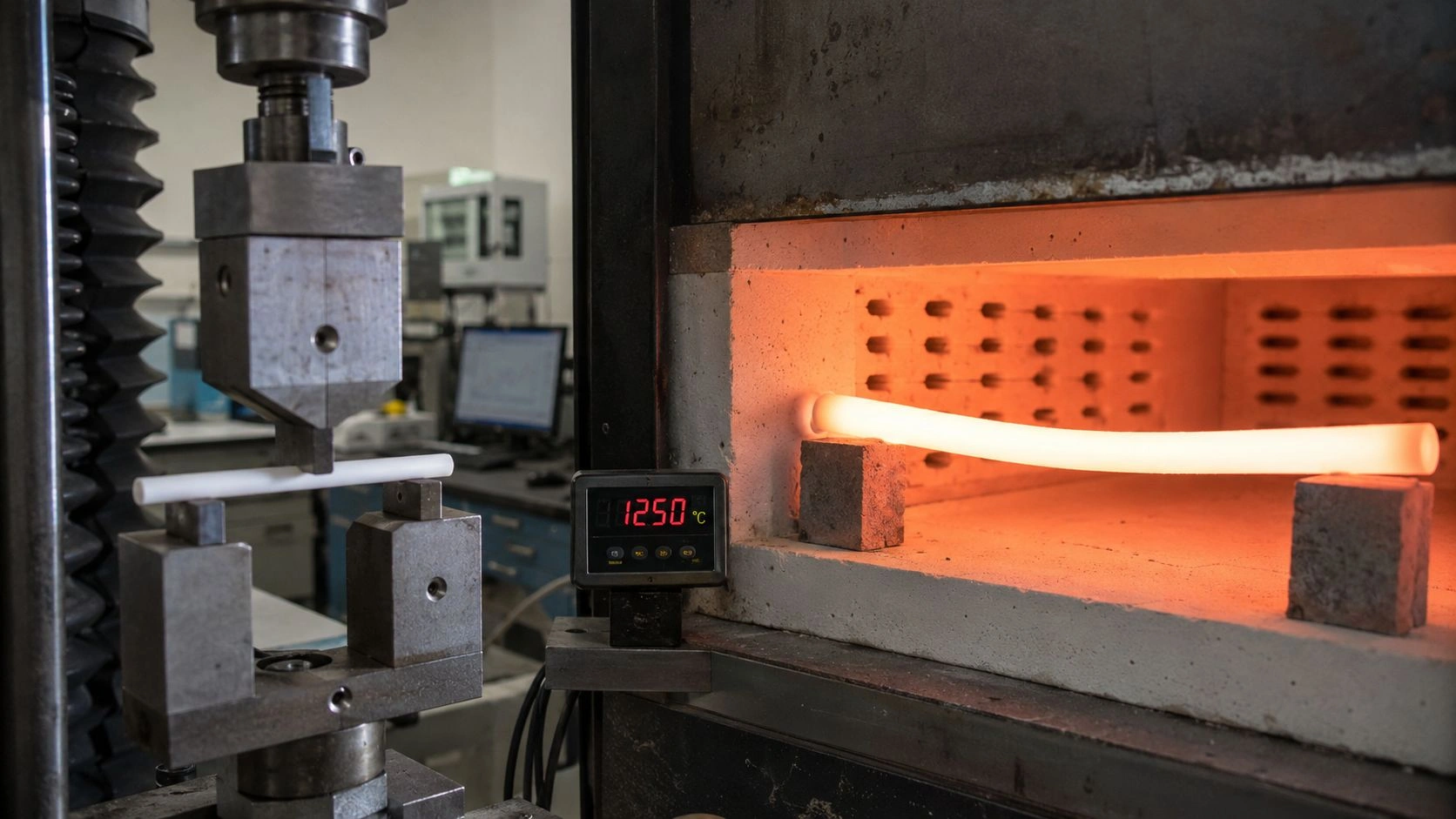
Permanent bowing or ovality developing over multiple furnace cycles indicates that the tube is experiencing time-dependent deformation under sustained hot load. Dense alumina has measurable creep behavior at temperatures within the cathode-calcination range, and this is amplified in long unsupported spans, in tubes with wall-thickness irregularities, or in operations where the hot-zone temperature is at the upper end of the cathode-calcination window. Bowing is a time-and-load failure mode, not a thermal-shock failure mode, and it responds to different specification variables — primarily unsupported span, wall thickness, and hot-flexural-strength data at service temperature.
Why cathode calcination damages alumina tubes earlier than generic furnace duty suggests
Cathode calcination is a coupled temperature–atmosphere–chemistry–geometry duty, not simply a "high-temperature furnace" exposure. Battery-industry process guidance places cathode calcination and sintering in the broad 700–900°C range, with oxygen control being critical to the final cathode structure and electrochemical performance. Research on cathode calcination as a manufacturing process confirms the coupling more explicitly: lithiation, dehydration, crystallization, and phase ordering proceed concurrently during calcination, and furnace method, mixing homogeneity, Li ratio, temperature profile, and atmosphere can all materially change the outcome.
That coupling matters for the alumina tube because the component does not only see heat — it sees oxygen flow, axial gradients along the furnace length, repeated thermal transients from charge loading and unloading, local deposition of lithium-bearing species, and whatever mechanical constraint the end seals and support geometry impose. A tube that is temperature-capable in a static, isothermal sense can still be systematically under-specified for this service if its transient thermal durability, hot-load stability, and surface chemical behavior have not been characterized against these combined drivers.
The industrial furnace ceramics context that surrounds this specific tube — heating elements, support rails, kiln furniture, and end hardware — contributes additional thermal mass and expansion compatibility requirements that the tube specification should acknowledge.
Why 700–900°C battery duty is not equivalent to generic laboratory furnace duty
A tube heated once to 900°C and allowed to cool slowly in still air is in a fundamentally different stress state from a tube that is ramped to 800°C in oxygen, held for hours, then cooled while the furnace loads new product at ambient temperature. The former is a thermal-soak test. The latter is a thermal-transient duty with oxidizing gas flow, potential reactive chemistry, and mechanical load from support rails and end fixtures. ASTM C1525 exists precisely because thermal-shock resistance under transient conditions must be tested explicitly — it cannot be inferred from maximum soak temperature alone.
Why oxygen flow and hot-zone gradients matter more than a catalog temperature line
Oxygen flow through a tube furnace creates a gas-velocity boundary layer at the bore surface, which affects local cooling rates, surface chemistry, and deposit behavior in ways that still-air characterization does not capture. Axial temperature gradients — which are steeper in tube furnaces than in well-mixed box furnaces — create differential thermal expansion along the tube length that adds to the stress state during ramp-up and ramp-down. Both effects are process-design variables, not material-property variables, but they belong in the specification conversation because they determine what the tube actually experiences.
Which symptoms are being misdiagnosed as "bad alumina"
The most expensive mistake in this application is assigning all observed problems to ceramic material quality before separating three different underlying phenomena. Each one requires a different corrective action, and conflating them leads to repeat purchases that reproduce the same failure because the real cause was never addressed.
At 720°C in pure O₂ for 12 hours, DOE comparison work showed tube-furnace calcination produced more heterogeneous primary morphologies than box-furnace calcination under the studied conditions. That result means variable cathode powder quality is not automatically a tube failure signature — it can be a process-route and calcination-uniformity problem wearing a hardware label. Before attributing any batch inconsistency to tube condition, the process variables need to be ruled out.
The Failure Mode Classification Table below is the diagnostic anchor for this section. Each row maps a visible symptom to its probable root cause, the diagnostic signature that distinguishes it from look-alike problems, and the prevention direction or threshold that determines the corrective specification action.
| Failure mode | Root cause | Diagnostic signature | Prevention threshold / decision direction |
|---|---|---|---|
| Longitudinal crack after ramp-down | Thermal gradient + brittle response under transient cooling | Crack emerges after cooldown; often aligned with hot/cold transition zone | Require transient-thermal validation logic consistent with ASTM C1525; do not qualify by soak temperature alone |
| Permanent bowing / ovality before fracture | Hot-load distortion, time-at-temperature, flaw sensitivity | Tube no longer runs true; sealing/alignment degrades before full breakage | Require elevated-temperature flexural justification and hot-life discussion; per ASTM C1211, hot behavior can depend on creep and slow crack growth |
| Inner-wall reaction / glaze / contamination | Lithium-bearing species reacting with alumina | Surface conversion layer, deposit, unexplained Li–Al–O residues, batch contamination | If LiOH·H₂O or Li₂CO₃ contact is plausible, treat compatibility as a mandatory RFQ item; Li–Al–O phases can form in the 500–800°C window |
| End-localized cracking | Differential expansion + seal or fixture restraint | Crack origin near flange, end cap, or fixed support point | Fix one end and allow controlled expansion at the other; document seal-zone temperature management |
| Powder inconsistency blamed on tube failure | Calcination heterogeneity from mixing / Li ratio / furnace route | Variable primary morphology without corresponding ceramic damage evidence | Check process uniformity first; tube-furnace route can produce more heterogeneous primaries than box-furnace route under the same chemistry |
Values indicative; verify per ASTM C1525 / ASTM C1211 / supplier-specific hot-service test data.
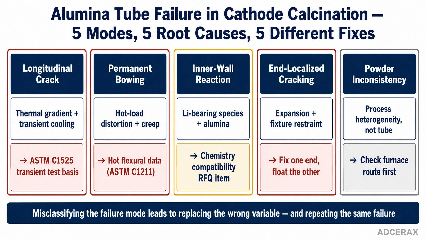
Five failure modes, five different root causes — correct classification at the first symptom determines whether the corrective action changes the ceramic grade, the process program, or the installation geometry.
Calling every early-failed tube "bad alumina" leads to repeat purchase, repeat installation, and repeat failure. The diagnosis must separate ceramic material quality from process heterogeneity, from installation restraint, from lithium-surface chemistry.
Process heterogeneity is not always hardware failure
Primary-particle morphology variation, batch-to-batch lithiation inconsistency, and non-uniform secondary particle size distribution are all evidence that the calcination process itself needs attention. They do not automatically indicate that the tube has cracked, reacted, or changed its geometry. Ruling out process-uniformity causes — furnace temperature uniformity, Li excess, precursor particle-size distribution, oxygen partial pressure, and mixing homogeneity — before assigning the cause to tube degradation prevents the costly cycle of replacing equipment that was not the root cause.
Surface conversion is not the same as thermal-shock cracking
An inner bore surface that shows a gray, glazed, or deposit-covered appearance after service is a chemical signal, not a mechanical failure signal. Peer-reviewed studies on lithium hydroxide reacting with alumina report lithium aluminate phase formation in the 500–700°C range, and related work on lithium carbonate with alumina identifies α-LiAlO₂ formation conditions that overlap the cathode-calcination window. A tube with a converted inner surface may still be mechanically intact — or it may be contaminating the cathode charge with aluminum-bearing species. Either outcome requires a different response from a tube that has cracked under thermal shock.
Which variables belong in the replacement specification
For this application, the replacement specification should not be written around one line — "alumina, max temperature X." It should be written around five linked variables that together define whether the tube is purchased as a calcination component or as a generic ceramic cylinder.
ASTM C1211 explicitly notes that hot flexural strength may depend on creep, stress corrosion, or slow crack growth — meaning room-temperature data are not sufficient to characterize the component's behavior in this service. That is the central reason why the specification needs to address elevated-temperature performance data, not only purity and dimensional tolerances.
Variable 1 — Grade and purity. Denser, higher-purity alumina (typically ≥99.5% Al₂O₃ for demanding calcination duty) offers lower porosity and better hot stability than lower-grade material. IEC-based grade distinctions are common in industrial alumina-tube supply and provide a structured basis for grade comparison.
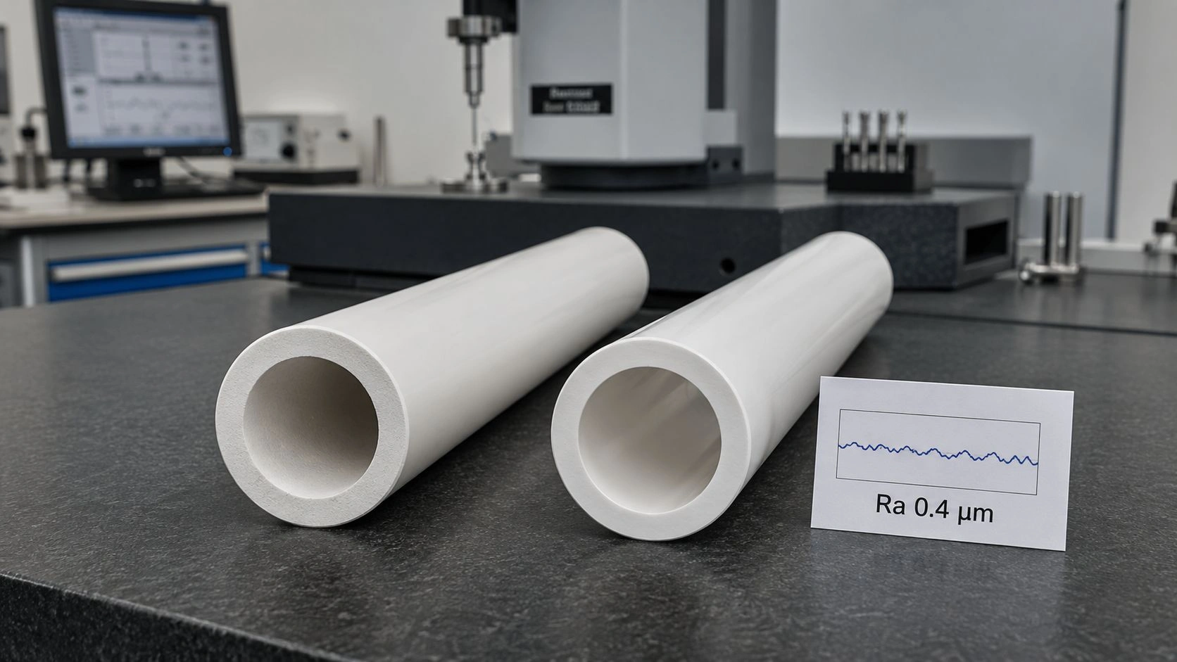
Variable 2 — Geometry under hot load. Unsupported span, outer diameter, wall thickness, and end condition jointly determine whether the tube sees stable service or distortion before fracture. These belong in the specification together, because a thin-wall tube with a long unsupported span behaves very differently from a thick-wall tube on two close supports — even at identical soak temperatures.
Variable 3 — Thermal-transient control. Because ASTM C1525 frames thermal-shock resistance as a transient-condition measurement, any supplier claim about calcination durability must reference transient-duty testing, not soak-temperature ratings alone. The specification should require the supplier to disclose the test basis for any thermal-durability claims.
Variable 4 — Hot mechanical reliability. Elevated-temperature flexural data and slow-crack-growth data — aligned to ASTM C1211 and ASTM C1465 logic — matter here because the tube accumulates both hot-load cycles and thermal transients. A supplier who can provide only room-temperature strength data is not answering the relevant question for this application.
Variable 5 — Process chemistry compatibility. When LiOH·H₂O or Li₂CO₃ exposure or carryover from the charge is plausible, the specification must include a compatibility confirmation for the inner surface behavior in lithium-bearing environments at the planned calcination temperature. For high-temperature ceramic tubes used in chemically active calcination atmospheres, material compatibility with the process chemistry is as important as mechanical durability.
Geometry and support belong in the ceramic specification, not only the furnace drawing
Unsupported span and end-fixation conditions are sometimes treated as furnace-design decisions that are independent of the tube specification. For alumina tubes in calcination service, that separation is incorrect. The tube wall must transmit the loads imposed by its own weight, the furnace's thermal gradient, and any restraint force at the seals. All of those loads depend on span, diameter, wall thickness, and end condition. Writing them into the tube specification — not only into the furnace assembly drawing — ensures that the supplier can confirm or challenge the design rather than discovering a compatibility problem after delivery.
Compatibility with lithium-bearing deposits must be treated as a specification item
If the calcination process involves lithium hydroxide or lithium carbonate in intimate contact with the tube bore — through powder carryover, gas-phase transport, or direct charge contact with the wall — the tube is not operating as an inert container in the chemical sense. Lithium aluminate formation is thermodynamically plausible at cathode-calcination temperatures, and the product phases may contaminate subsequent cathode batches with aluminum or change the bore surface in ways that affect local thermal contact and gas flow. Including a compatibility confirmation requirement in the RFQ converts this from a risk assumption to a verified specification item.
What should go into the RFQ and supplier verification pack
Before placing the next order, the RFQ should specify five things that are currently missing from most generic tube orders for this application: transient-thermal performance basis, hot-load behavior at service temperature, slow-crack-growth or durability data at temperature, installation and expansion guidance, and chemistry compatibility with lithium-bearing environments.
The specification checklist for alumina tube applications in Li-ion cathode calcination service:
- Alumina grade and nominal purity range — ≥99.5% Al₂O₃ as the starting threshold for purity-sensitive cathode service; confirm grain size and secondary-phase content for highest-reliability grades.
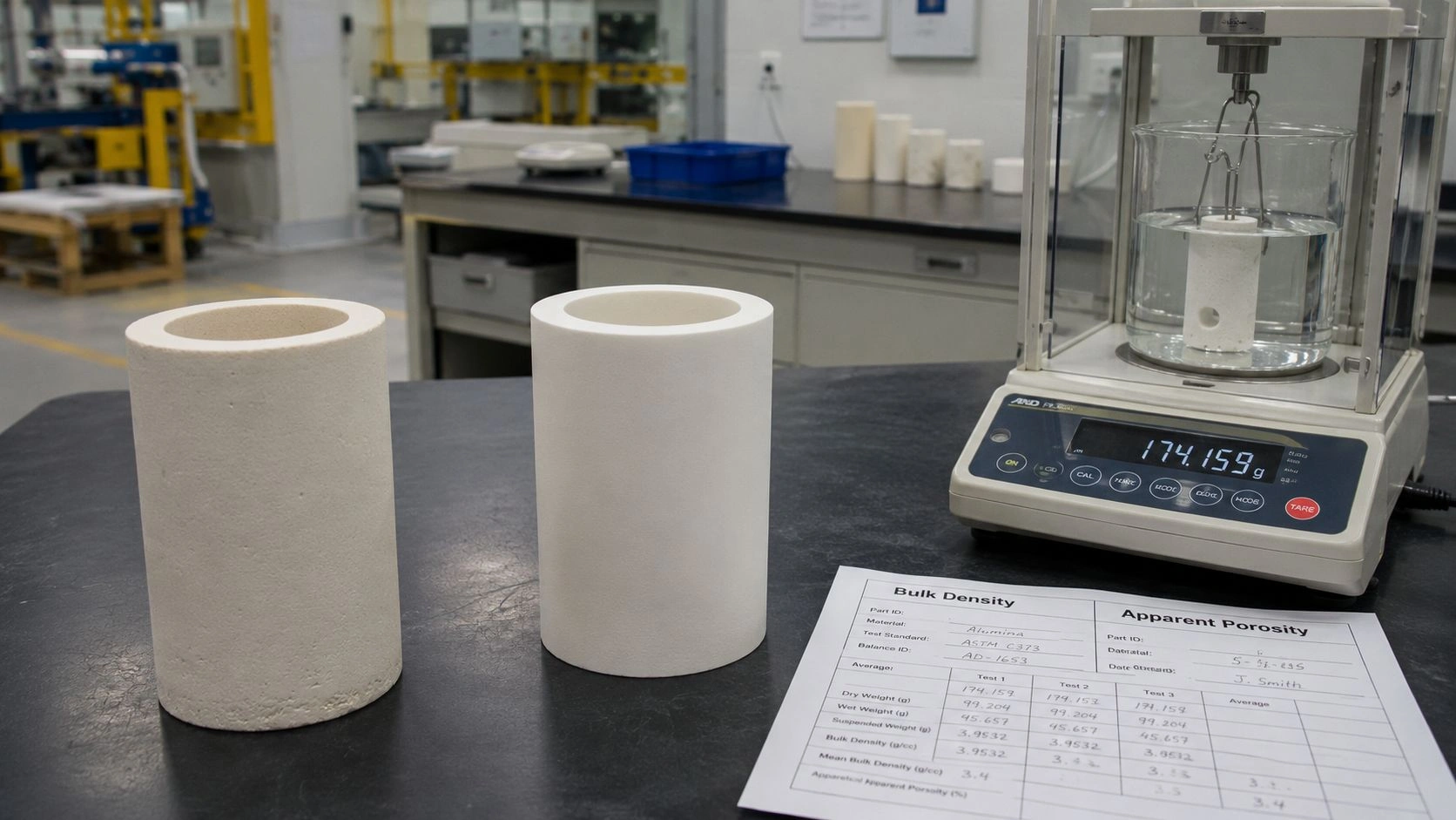
- Density and porosity confirmation — request measurement method and values; higher density reduces both internal defect density and bore-surface area accessible to lithium-bearing species.
- Continuous and peak service temperature by atmosphere — confirm limits for O₂-rich atmospheres specifically, not only still-air limits.
- Thermal-shock testing basis — require the supplier to confirm that thermal-shock durability claims are backed by a test method consistent with ASTM C1525 logic, not only catalog temperature ratings.
- Elevated-temperature flexural data — request strength measurements at the planned service temperature, or a reference to applicable elevated-temperature test data; per ASTM C1211, room-temperature data are insufficient for hot-service specification.
- Slow-crack-growth or stress-rupture discussion — ask whether durability data relevant to ASTM C1465 logic are available for the specific grade and temperature range; if not, request the supplier's assessment of time-dependent failure risk for the planned cycle count.
- Maximum unsupported span recommendation — request the supplier's guidance for the specific tube geometry and service conditions, not a generic catalog figure.
- End-fixation guidance — confirm that one end is fixed and the other is permitted to float for thermal expansion; request the supplier's recommended end-zone temperature management approach.
- Inner-surface compatibility with LiOH/Li₂CO₃ exposure — require a written response on whether the inner bore surface has been characterized for lithium-bearing environments at calcination temperatures; if not, treat this as an open qualification item.
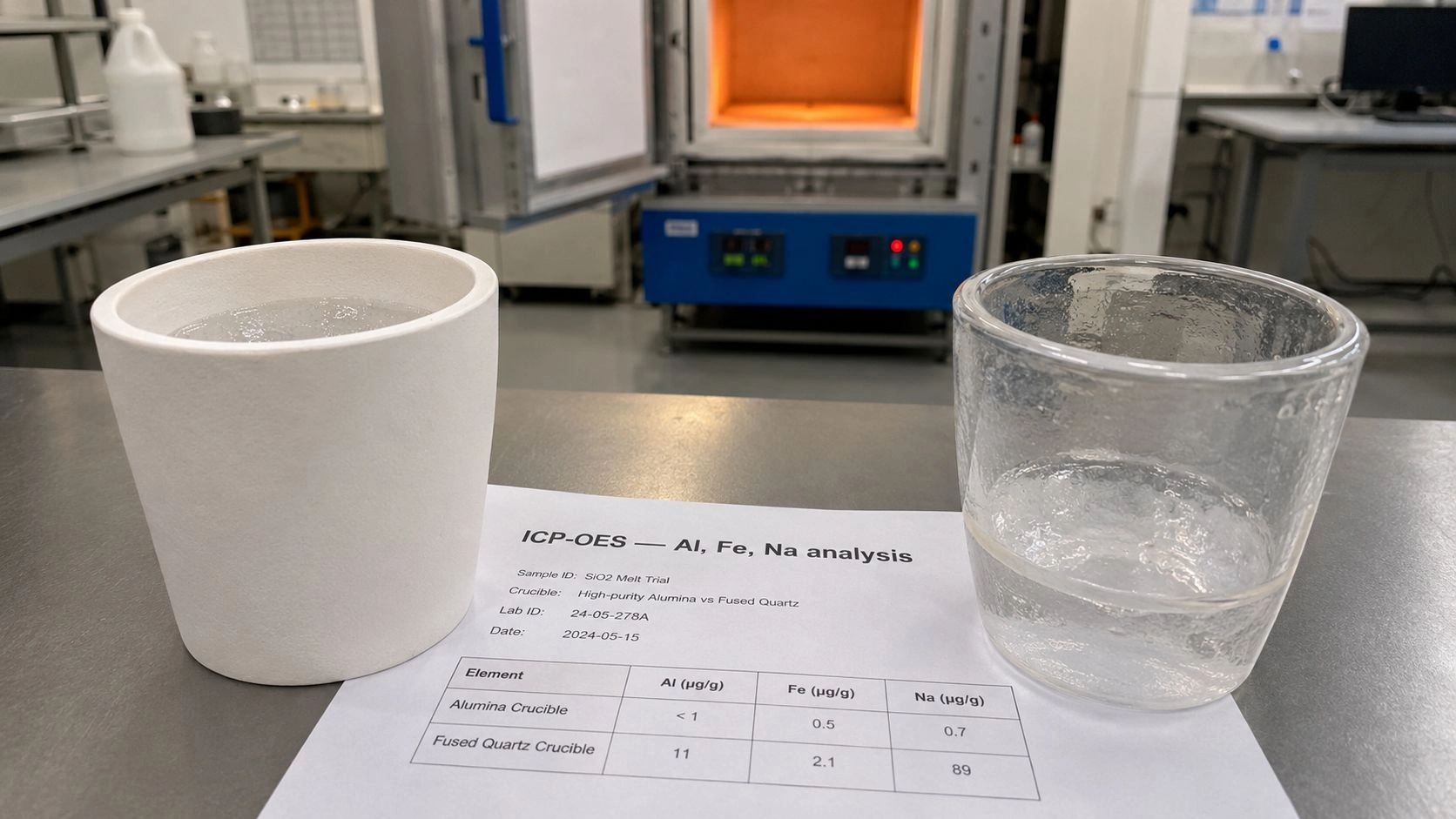
- Contamination control documentation — for cathode service, request trace-element data for the alumina body that confirm absence of species harmful to cathode electrochemistry.
If the supplier discussion stops at purity and maximum temperature, the buyer is still purchasing a catalog tube rather than a calcination component. The two documents that define the difference are the supplier's elevated-temperature test data and their explicit response to the lithium-compatibility item.
Conclusion
Early alumina-tube failure in Li-ion cathode calcination is a combined-service problem: thermal transients, hot-load cycling, axial gradients, oxygen atmosphere, installation restraint, and possible lithium-alumina chemistry all act on the same component simultaneously. Diagnosing which mode appeared first and distinguishing true tube failure from process heterogeneity prevents the cycle of repeat purchases without root-cause correction. Writing the replacement specification around transient durability, hot-load behavior, expansion management, and chemistry compatibility — not around purity and catalog temperature alone — converts the failure analysis into a component that is actually qualified for the duty.
Investigating an alumina tube failure in cathode calcination or drafting a replacement specification? Send the furnace temperature profile, atmosphere, cycle count, current tube grade, failure location and crack morphology, and any known lithium-source contact history. ADCERAX engineers return a root-cause assessment with replacement tube recommendation, specification notes for transient-thermal and hot-load performance, and supplier-data requirements for the confirmed failure mode.
Frequently Asked Questions
Is early alumina-tube failure in cathode calcination usually a temperature-limit problem?
Usually not. In this duty, early failure is more often a combined problem involving thermal gradients during heating and cooling, repeated thermal cycling, installation restraint at the end seals, and possible lithium-bearing surface interaction — rather than a case where the furnace setpoint simply exceeds the catalog maximum temperature. That is why the failure analysis cannot stop at a temperature comparison.
Can lithium precursors actually interact with alumina during calcination?
Yes, that risk is technically plausible within cathode-calcination temperature windows. Peer-reviewed studies on lithium hydroxide with alumina report lithium aluminate phase formation in the 500–700°C range, and related work on lithium carbonate with alumina identifies α-LiAlO₂ formation conditions that overlap common cathode-calcination windows. If lithium-bearing material contacts the tube bore wall through carryover, gas-phase transport, or direct charge contact, the tube is no longer fully inert in the chemical sense.
If powder morphology looks inconsistent, does that prove the tube is failing?
No. Primary morphology variation and batch-to-batch lithiation inconsistency can be process-uniformity problems rather than ceramic failure evidence. DOE comparison work showed that tube-furnace calcination produced more heterogeneous primary morphologies than box-furnace calcination at 720°C in pure O₂ for 12 hours — under comparable chemistry — indicating that furnace route and calcination uniformity affect powder quality independently of ceramic condition.
What is the single most common specification mistake?
Writing the RFQ around alumina purity and maximum catalog temperature only. For cathode calcination service, the specification should also require transient-thermal durability testing consistent with ASTM C1525, hot flexural behavior data per ASTM C1211 logic, slow-crack-growth or durability data relevant to ASTM C1465, expansion management guidance, and compatibility confirmation for lithium-bearing bore environments.
Which test logic matters most before reordering?
A combination approach rather than a single number. Thermal-shock resistance testing aligned to ASTM C1525, elevated-temperature flexural behavior per ASTM C1211 — noting that room-temperature strength is not sufficient because hot strength can depend on creep and slow crack growth — and slow-crack-growth or time-dependent durability discussion per ASTM C1465 are each addressing a different failure mode. Specifying which test results the buyer needs, before placing the order, converts the supplier discussion from a catalog comparison to a qualification review.