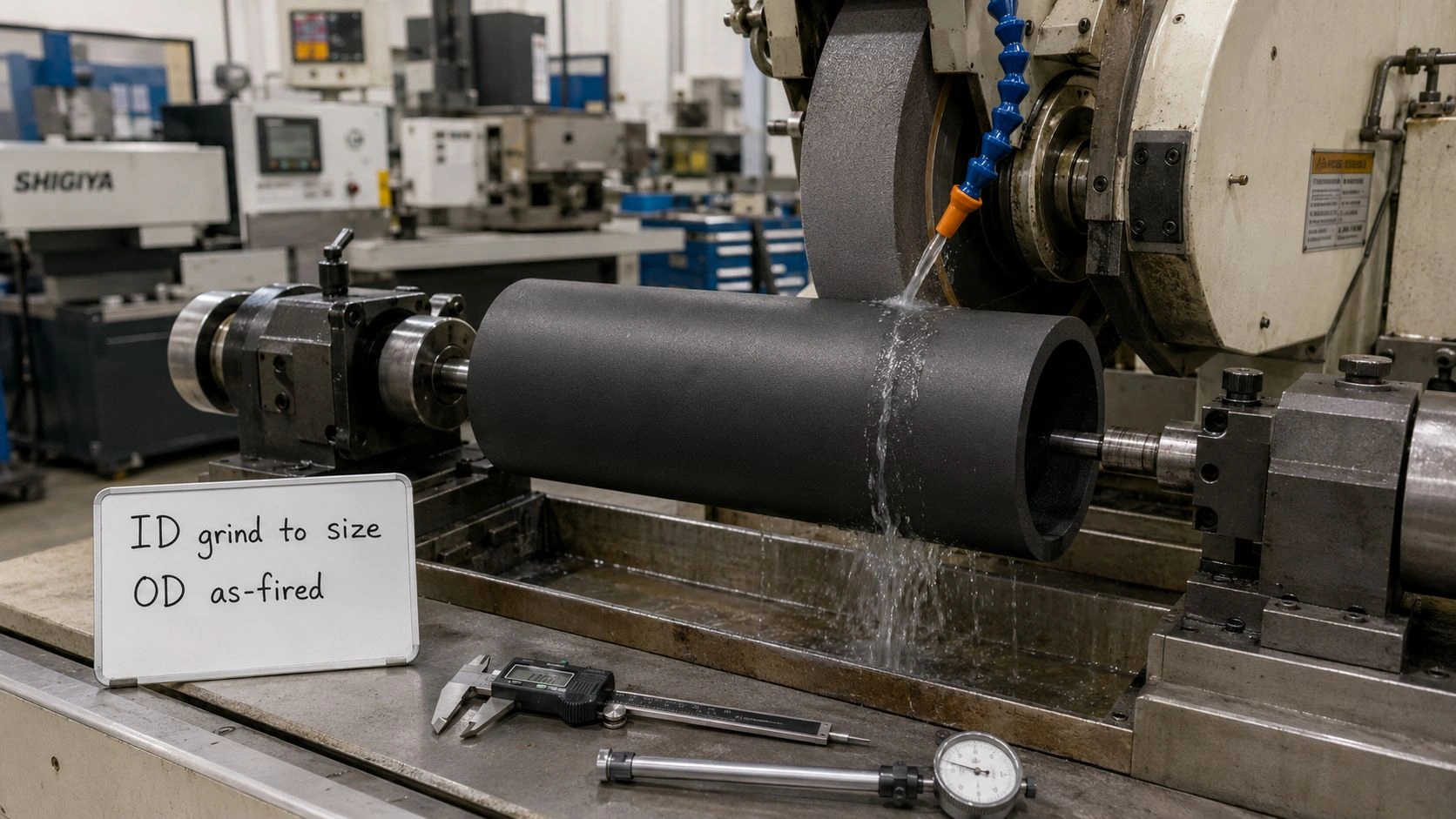
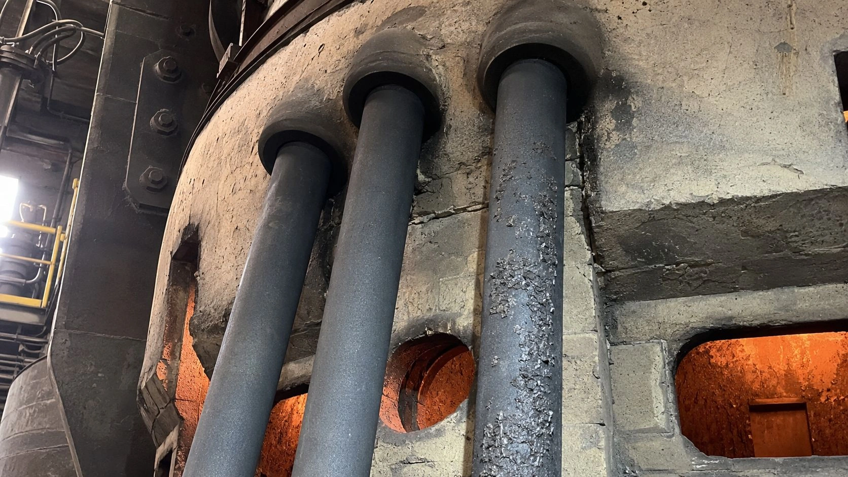
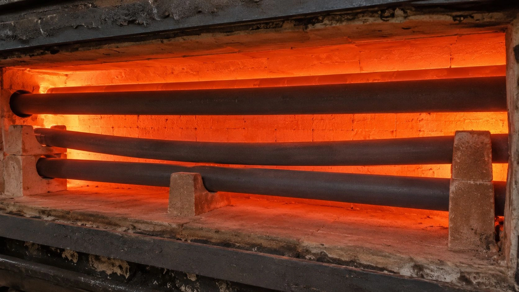
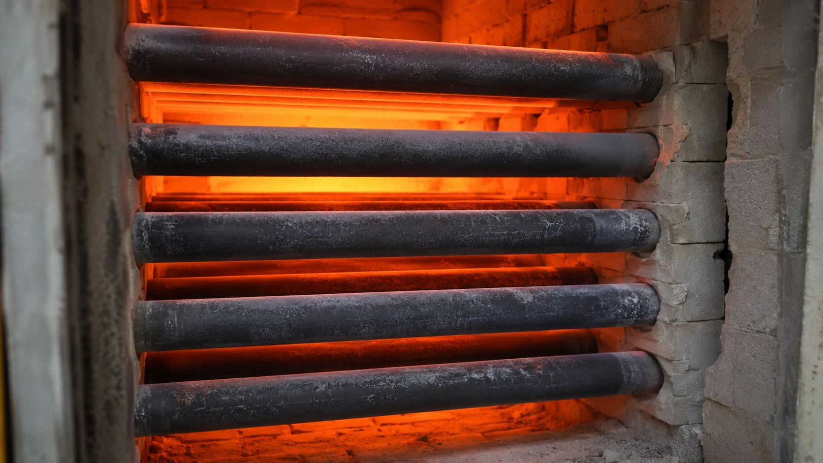
SiC tubes and liners can be used in solar polysilicon CVD reactors when the component must withstand high temperature, hydrogen-and-chlorosilane chemistry, HCl-containing byproducts, silicon deposition, thermal cycling, abrasion, and strict contamination limits. Their role depends on the reactor type: in Siemens bell-jar reactors, SiC may serve as protection, support, insulation, or gas-handling hardware; in fluidized-bed reactors, SiC liners and tubular segments are more directly relevant because granular silicon flow and reactor-wall contamination are major concerns. The correct specification must define reactor type, gas chemistry, temperature, purity limits, deposition behavior, cleaning cycle, tube geometry, and SiC grade — not temperature rating alone.
That reactor-role-first specification discipline is the engineering principle this guide builds around.
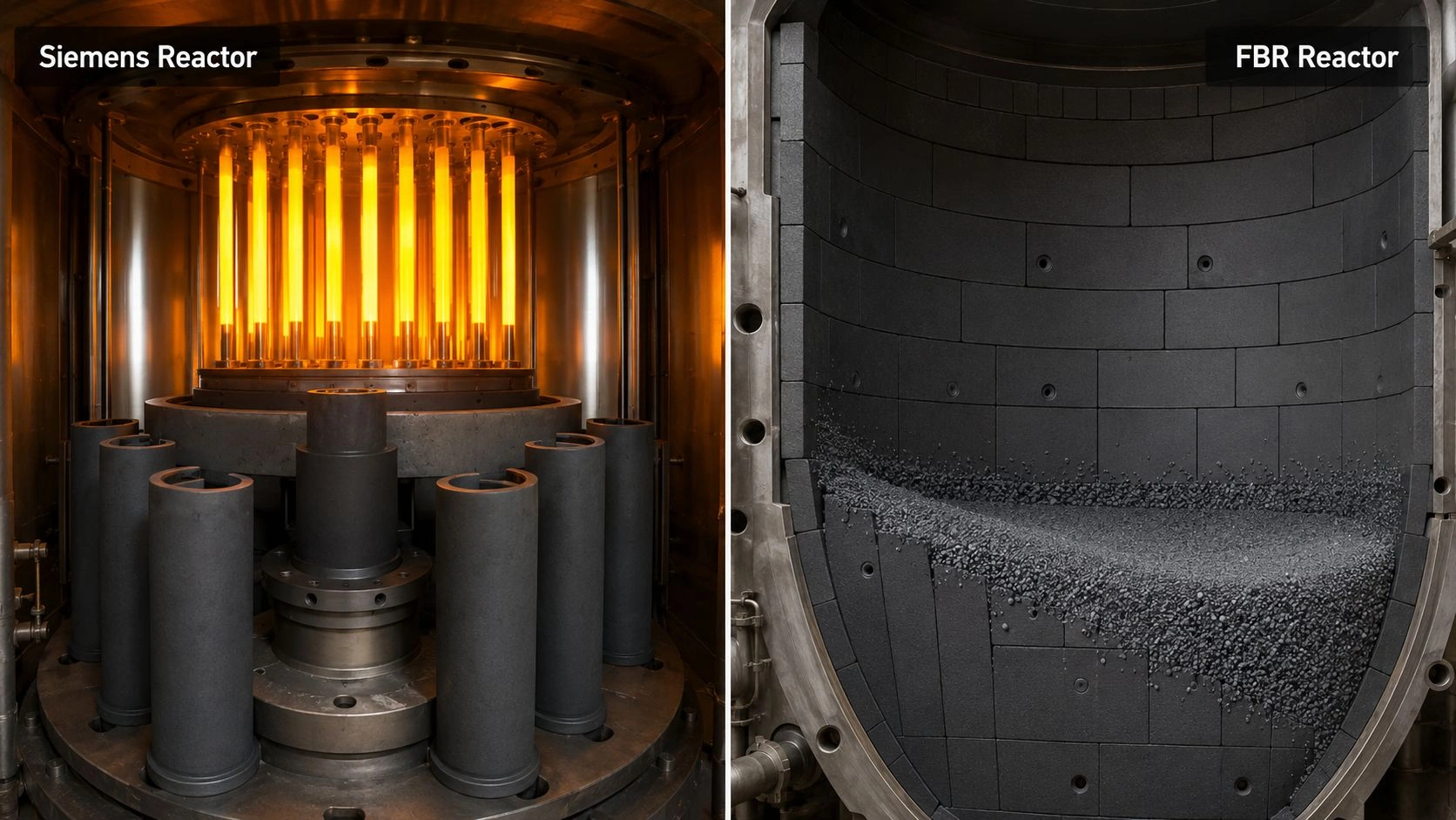
SiC tubes and liners in solar polysilicon CVD reactors face combined exposure to trichlorosilane or silane, hydrogen, HCl byproducts, silicon deposition, and strict purity constraints — reactor type and process zone determine which SiC grade and geometry apply.
This article is part of ADCERAX's coverage of silicon carbide tubes for high-temperature, chemical-resistance, and process applications, which includes SSiC, RBSiC, and NSiC grades for industrial protection tube, liner, and process-tube service.
Where SiC tubes fit in polysilicon CVD reactors
The first decision in any polysilicon CVD reactor SiC specification is reactor type, because Siemens bell-jar reactors and fluidized-bed reactors impose fundamentally different service conditions on ceramic internal components.
The SiC Tube Use Boundary table below maps the main reactor zones to SiC fit:
| Reactor/zone | SiC tube or liner fit | Main advantage | Main risk | What to verify |
|---|---|---|---|---|
| Siemens bell-jar reactor hardware | Possible for protection, supports, gas-handling, insulation | High temperature and chemical stability | Deposition build-up and purity risk | TCS/H₂/HCl exposure, cleaning cycle |
| Graphite-adjacent components | Possible as sleeve or coating route | Barrier against contamination or attack | Thermal mismatch and assembly stress | Graphite interface and expansion |
| Gas inlet/distributor area | Possible with custom geometry | Thermal shock and corrosion resistance | Local deposition or plugging | Flow pattern and precursor concentration |
| FBR liner/internal segment | Strong candidate with validation | Abrasion and contamination control | Particle erosion and joint design | Liner segmentation and bonding |
| FBR tubular insert | Possible | Wear-resistant flow boundary | Plugging and fines abrasion | Particle load and flow velocity |
| Chlorosilane recycle/hot gas zones | Conditional | SiC chemical resistance | HCl/condensate/thermal cycling | Representative exposure test |
| Direct product-contact surface | Use caution | Low contamination if grade is suitable | Trace impurities/particle shedding | Purity, porosity, packaging, cleaning |
Values indicative; verify with reactor-specific gas chemistry, temperature profile, supplier SiC grade data, and application validation.
Siemens reactor: protection, support, insulation, and gas-handling hardware. In the Siemens process, trichlorosilane is converted to silicon by CVD on electrically heated silicon filaments or rods inside a closed bell-jar reactor. Published process descriptions note that silicon filaments are heated to approximately 1150°C for TCS deposition until they become polysilicon rods. In that architecture, graphite electrodes and seed chucks are standard reactor components. SiC in a Siemens reactor is most naturally positioned as protective sleeves, electrical insulation components, gas inlet hardware, or support structures — not as the primary silicon-contact surface, which is typically the silicon rod itself.
FBR reactor: liners, tubular segments, flow-path protection, and abrasion resistance. In fluidized-bed reactor polysilicon production, silicon grows on suspended granular seed particles rather than on fixed rods. Published engineering descriptions of FBR systems characterize the process as silane decomposition where seed particles grow by heterogeneous CVD and by scavenging silicon powder from homogeneous gas-phase nucleation in the gas stream. The reactor wall and internal flow-path components must resist particle motion, silicon deposition on surfaces, contamination from reactor hardware, and abrasive wear. SiC liners and segmented tubular internals are directly relevant in this environment because they can address abrasion, contamination, and deposition simultaneously in a way that metal reactor walls cannot.
Why SiC tubes should not be specified without reactor type. Specifying "SiC tube for polysilicon reactor" without identifying reactor type is equivalent to specifying "ceramic tube for furnace" — the answer depends entirely on what the furnace does. A Siemens reactor operates at moderate temperature but with complex chlorosilane and hydrogen chemistry near graphite hardware. An FBR operates at different temperature profiles, with particle flow, pressure control, and silicon granule growth as the primary design drivers. Each reactor creates a different set of SiC tube requirements.
Why the polysilicon CVD environment is hard on ceramic tubes
After identifying the reactor zone, the gas chemistry and contamination requirements determine which aspects of SiC performance actually matter.
[CITE: Published process data confirms that Siemens polysilicon production uses trichlorosilane and hydrogen at temperatures up to approximately 1150°C, producing HCl and silicon tetrachloride as byproducts alongside the deposited silicon product — and high-temperature corrosion research on CVD SiC exposed to 5% HCl in hydrogen at 1200°C found that corrosion resistance depended on SiC film microstructure and preferred crystallographic orientation, confirming that "SiC" is not one uniform material in chlorinated hydrogen environments and that the specific grade, microstructure, and surface condition must be matched to the reactor gas chemistry rather than specified by temperature rating alone.]
Chlorosilane and HCl-containing gas exposure. The gas environment in a Siemens or FBR polysilicon reactor can include trichlorosilane, monosilane, dichlorosilane, silicon tetrachloride, HCl, and hydrogen — and the relative concentrations and temperatures of these species vary by reactor zone and process stage. In chlorosilane/hydrogen service at elevated temperature, the SiC surface chemistry and microstructure determine corrosion rate. Published corrosion research confirms that CVD SiC behavior in 5% HCl/H₂ at 1200°C depends on film orientation and microstructure — meaning that "SiC grade" is a real specification variable, not a branding distinction.
Silicon deposition and surface build-up. Silicon deposition on reactor internal surfaces is not only a process efficiency issue — it is a SiC tube management issue. When silicon deposits on a SiC surface and accumulates, the deposit can crack the tube during thermal cycling due to the mismatch in thermal expansion between silicon and SiC, or can build to the point of flow obstruction. The tube specification must consider deposition tolerance, the cleaning or stripping cycle that will be used to remove deposits, and whether the SiC surface survives cleaning without damage.
Hydrogen atmosphere and thermal cycling. Both Siemens and FBR polysilicon processes operate in hydrogen-dominant reducing atmospheres. Pure hydrogen at high temperature is generally compatible with SiC, but the combination of hydrogen, chlorosilane chemistry, and thermal cycling creates a demanding mechanical and chemical environment. Rapid thermal cycling — common during reactor maintenance, rod harvesting, or seed charging — imposes thermal shock on ceramic components that must be matched to the SiC grade's thermal shock resistance.
Contamination sensitivity in solar-grade polysilicon. Solar-grade polysilicon purity requirements have tightened substantially as cell efficiencies have improved. The ceramic tube is one of many potential contamination sources in the reactor — alongside graphite hardware, metal seals, gas-line materials, and process chemistry. For a SiC tube to be acceptable in direct or near-product contact, its trace impurity profile, open porosity, particle shedding behavior, and cleaning protocol all require validation. A tube that is chemically stable in chlorosilane gas is not automatically suitable for product contact if it has high open porosity or undefined trace impurity levels.
Choosing the SiC route: SSiC, RBSiC, CVD SiC, ReSiC, or SiC-coated graphite
After confirming reactor zone and chemistry, the SiC grade decision determines which material route can deliver the required combination of contamination control, chemical resistance, abrasion tolerance, and geometric capability.
The SiC Material Route Matrix maps the main grade options:
| SiC route | Best-fit role | Main advantage | Main boundary |
|---|---|---|---|
| SSiC | Dense tubes, sleeves, high-purity chemical-exposure parts | Low porosity, strong corrosion resistance | Cost, machining difficulty, size limits |
| RBSiC/SiSiC | Larger liners, segmented shapes, structural internals | Near-net forming and geometry flexibility | Residual silicon and purity boundary |
| CVD SiC | High-purity surface layer or coated part | Dense, clean surface | Cost, coating integrity, substrate mismatch |
| ReSiC | High-temperature structural hot-zone hardware | Thermal stability and SiC purity | Open porosity/gas-tightness concerns |
| SiC-coated graphite | Graphite thermal/structural core with clean SiC surface | Combines graphite function and SiC barrier | Coating cracks, pinholes, thermal mismatch |
| Alumina/quartz alternative | Non-SiC routes for specific zones | Lower cost or silica compatibility | May lack wear/thermal shock/chlorosilane resistance |

SSiC for dense, low-porosity chemical-exposure parts. Dense sintered silicon carbide provides the lowest open porosity among the mainstream SiC grades, which is directly relevant for polysilicon applications where high porosity means silicon fines and process chemicals can penetrate the tube body and either contribute to contamination or create internal stress during thermal cycling. For protection tubes, gas-handling sleeves, and small precision components near the high-temperature reactor zone, SSiC is typically the starting point.

RBSiC/SiSiC for larger segmented liners and complex shapes. Reaction-bonded SiC can be manufactured into larger and more geometrically complex shapes than sintered SiC because it does not shrink as much during the conversion process. For FBR liners and segmented reactor-wall components that require precise fit across large cross-sections, RBSiC is often the practical manufacturing route. The critical caution is the residual silicon phase in RBSiC — which melts above approximately 1420°C and which may be incompatible with ultra-high-purity polysilicon requirements depending on the contact zone and temperature profile.
CVD SiC where surface purity dominates. Patents for polysilicon fluidized-bed reactors specifically disclose segmented silicon carbide liners including non-contaminating bonding materials and reaction-bonded SiC options for producing polysilicon-coated granular material. This patent context confirms that the industry treats SiC liner design as an engineered system — including how liner segments are joined and how contamination is minimized at segment boundaries — rather than as a simple tube-material substitution. CVD SiC coatings on graphite or other substrates provide the cleanest possible SiC contact surface but require careful attention to coating integrity, especially at edges, holes, and thermal cycling boundaries.
The silicon carbide ceramic material grades — SSiC, RBSiC, and NBSiC — differ in density, residual phase, and impurity profile in ways that directly affect polysilicon purity and contamination risk. The ceramic tubes and pipes range across SiC, alumina, zirconia, and BN provides cross-material context for cases where SiC is not the correct route for a specific reactor zone.
Do not misdiagnose reactor fouling or deposition as SiC failure
When a SiC tube or liner in a polysilicon CVD reactor shows heavy silicon deposits, plugging, surface roughening, cracking, or post-cleaning damage, the diagnosis should not immediately default to SiC grade failure. Each of these symptoms has multiple possible causes.
Silicon build-up vs SiC surface incompatibility. Silicon deposits form on SiC surfaces when the gas-phase supersaturation at the tube surface exceeds the threshold for heterogeneous nucleation. This depends primarily on local temperature, precursor concentration, and gas flow velocity — not on the SiC surface chemistry. A tube that accumulates heavy silicon deposit in one reactor position may remain clean in a different position at the same temperature, because the gas-phase environment differs. Diagnosing the deposit source requires understanding the local gas-phase supersaturation, not only examining the tube material.
Gas distribution imbalance vs tube geometry problem. Plugging concentrated at one tube end or inlet often reflects flow distribution asymmetry in the reactor rather than a material incompatibility. If gas enters the tube at a position where velocity is low and supersaturation is high, silicon fines or condensate deposits will accumulate at that location regardless of whether the tube is SiC, quartz, or alumina. Reviewing the gas inlet geometry and flow distribution before attributing plugging to SiC grade is the correct diagnostic sequence.
Abrasion and fines in FBR service. In a fluidized-bed reactor, the primary failure mode for liner material is often abrasion from granular silicon particles rather than chemical corrosion. High particle velocity, high particle mass flux, and localized jet impingement at gas inlet points create erosion that accumulates over many operational hours. A SiC grade selected for chemical resistance without considering hardness, toughness, and surface condition may still fail by abrasion — which is a geometry and operating-condition problem, not a material-chemistry problem.
Thermal cycling and rigid support cracks. Cracks near support points or mounting hardware typically indicate thermal expansion mismatch rather than material-grade inadequacy. If the SiC tube is constrained at its ends by rigid connections that cannot accommodate thermal expansion, the resulting stress concentrates at the constraint and fractures the tube during thermal cycling. This is a mounting design problem that changing the SiC grade will not solve.
The Failure Diagnosis Matrix below maps observed problems to better diagnostic questions:
| Observed problem | Common assumption | Better diagnostic question |
|---|---|---|
| SiC tube has heavy silicon deposit | SiC surface failed | Was local gas supersaturation or temperature gradient causing deposition? |
| Tube ID plugs | Wrong material | Are silicon fines, homogeneous nucleation, or condensates accumulating? |
| Surface roughening | Chemical corrosion | Is particle abrasion or cleaning damage the main cause? |
| Crack near support | SiC too brittle | Was thermal expansion restrained or mounting too rigid? |
| Product contamination | SiC impurity | Did graphite hardware, seals, metals, or cleaning tools contribute? |
| FBR liner wear | Poor SiC grade | Is particle velocity or bed hydrodynamics driving erosion? |
| Post-cleaning chips | Bad material quality | Was cleaning chemistry, thermal shock, or mechanical scraping too aggressive? |
Diagnosis should be based on deposit chemistry, failure location, reactor gas-flow mapping, and process log review before any material change is specified.
RFQ checklist for SiC tubes in solar polysilicon CVD reactors
A complete RFQ for SiC tubes or liners in polysilicon CVD service must provide both the reactor zone context and the purity requirements — without both, the supplier cannot confirm grade suitability, surface finish, or appropriate cleaning and packaging protocol.
[CITE: Engineering guidance on SiC tube and liner specification for solar polysilicon CVD reactor internals confirms the complete RFQ sequence: reactor type and process zone, gas chemistry including TCS/silane/H₂/HCl/STC species, operating and peak temperature with pressure and thermal cycle, product purity target (solar-grade/mono-grade/electronic-adjacent), expected silicon deposition behavior and cleaning cycle, particle or fines exposure for FBR service, required SiC grade with density/open porosity/residual phase/trace impurity profile, tube or liner geometry including OD/ID/wall/length/ports/flanges/end configuration, surface finish and packaging cleanliness, and validation protocol including representative gas exposure or deposition trial — because gas chemistry, purity target, and deposition behavior together determine which SiC grade is appropriate, and a supplier who receives only "SiC tube for polysilicon reactor" cannot confirm grade suitability, contamination risk, or cleaning compatibility without the remaining context.]
| RFQ field | Why it matters | Recommended wording |
|---|---|---|
| Reactor type | Defines exposure mode | "Siemens bell jar/FBR/chlorosilane hot-gas zone" |
| Process chemistry | Primary compatibility driver | "TCS, silane, H₂, HCl, STC, DCS, condensates" |
| Temperature and pressure | Defines thermal and corrosion boundary | "Continuous, peak, pressure, and thermal cycle" |
| Product purity target | Controls contamination risk | "Solar-grade/mono-grade/electronic-adjacent purity target" |
| Deposition risk | Controls plugging and cleaning | "State expected silicon build-up and cleaning method" |
| Particle/fines exposure | Critical for FBR service | "Provide particle size, velocity, and bed contact condition" |
| SiC grade | Prevents generic mismatch | "Quote SSiC/RBSiC/CVD SiC/ReSiC/coated graphite" |
| Tube geometry | Controls flow, stress, and manufacturability | "OD, ID, wall, length, ports, flanges, end type" |
| Surface finish | Affects deposition and cleaning | "Specify ID/OD Ra only where functional" |
| Validation | Confirms real compatibility | "Request chlorosilane/H₂/HCl exposure or deposition trial if critical" |
RFQ fields are the minimum for a polysilicon CVD reactor SiC tube inquiry; add liner segmentation design, bonding material, and lot traceability for FBR liner applications.
For critical reactor internals — direct silicon-product contact, high-purity Siemens hardware near the deposition zone, or FBR liner segments at high particle flux — a representative chemistry exposure test or deposition trial using the actual gas species and temperature should be completed before production quantities are ordered.
Evaluating SiC tubes or liners for solar polysilicon CVD reactors? Share your reactor type, gas chemistry, temperature, pressure, purity target, particle exposure, deposition behavior, cleaning cycle, tube drawing, and required SiC grade. ADCERAX can review whether SSiC, RBSiC/SiSiC, CVD SiC, ReSiC, or SiC-coated graphite fits the reactor zone; turnaround depends on inquiry complexity — no commitment required at this stage.
Frequently Asked Questions
Are SiC tubes used in solar polysilicon CVD reactors?
Yes, but their role depends entirely on reactor type. In Siemens reactors, SiC may serve as protective sleeves, insulation hardware, gas inlet components, or support structures. In FBR systems, SiC liners and segmented internal components are more directly relevant because granular silicon particle flow, reactor-wall abrasion, and contamination control are primary design concerns. Published FBR patents explicitly disclose segmented SiC liners for polysilicon-coated granular material production.
Why is the polysilicon CVD environment difficult for SiC tubes?
The environment combines high temperature, hydrogen, trichlorosilane or silane, HCl-containing byproducts, silicon tetrachloride, silicon deposition on surfaces, silicon dust, condensable chlorosilanes, and strict solar-grade purity requirements. Published corrosion research confirms that SiC behavior in HCl/hydrogen at 1200°C depends on microstructure and orientation — meaning grade specification matters, not just material name.
Which SiC grade is best for polysilicon reactor service?
There is no universal grade. SSiC offers low porosity and strong corrosion resistance for chemical-exposure components. RBSiC/SiSiC enables larger segments and complex shapes but carries residual silicon that must be evaluated for purity impact. CVD SiC provides the cleanest surface but requires coating integrity review. ReSiC suits high-temperature structural roles but has open porosity. The correct choice depends on porosity, residual phase, contamination limits, geometry, abrasion resistance, and cleaning method.
Is CVD SiC better than sintered SiC for polysilicon reactors?
CVD SiC can offer a dense, clean surface with lower porosity and higher purity than some sintered SiC grades, which may be valuable where product contact purity is the governing requirement. However, coating integrity across thermal cycling, substrate compatibility, edge and hole coverage, and cost must be reviewed. CVD SiC is not automatically superior for all reactor zones — the correct choice follows from the specific exposure conditions and purity target.
What causes SiC tube failure in polysilicon reactors?
Common causes include silicon deposition build-up, particle abrasion in FBR service, thermal shock from rapid cycling, rigid mounting that restrains thermal expansion, cleaning damage from aggressive chemical or mechanical stripping, condensate attack in recycle-gas zones, and contamination from graphite or metal hardware adjacent to the SiC tube rather than from the SiC itself.
What information should I send to a supplier for a polysilicon reactor SiC tube inquiry?
Send reactor type, process chemistry including all gas species, operating and peak temperature with pressure, product purity target, expected silicon deposition behavior and cleaning cycle, particle size and flux for FBR applications, tube or liner drawing with OD/ID/wall/length and end configuration, required SiC grade, surface finish, and the validation protocol you intend to apply — including whether gas exposure or deposition testing is required before production quantities are ordered.