SiC tubes are suitable for high-temperature gas filtration when the component is designed as a porous filter tube or candle element — not as a dense structural tube. Their value comes from combining thermal shock resistance, corrosion resistance, creep resistance, high filtration efficiency, and back-pulse cleanability in hot dust-laden gases. The correct specification must define gas temperature, dust chemistry, particle size, flow rate, pressure drop, pore structure, membrane layer, flange strength, cleaning method, and allowable thermal cycling. A dense SiC process tube — however temperature-capable — cannot replace a porous candle filter, because it has no engineered permeability or particle-capture structure.
That porous-versus-dense distinction is the first and most important engineering boundary this guide draws.
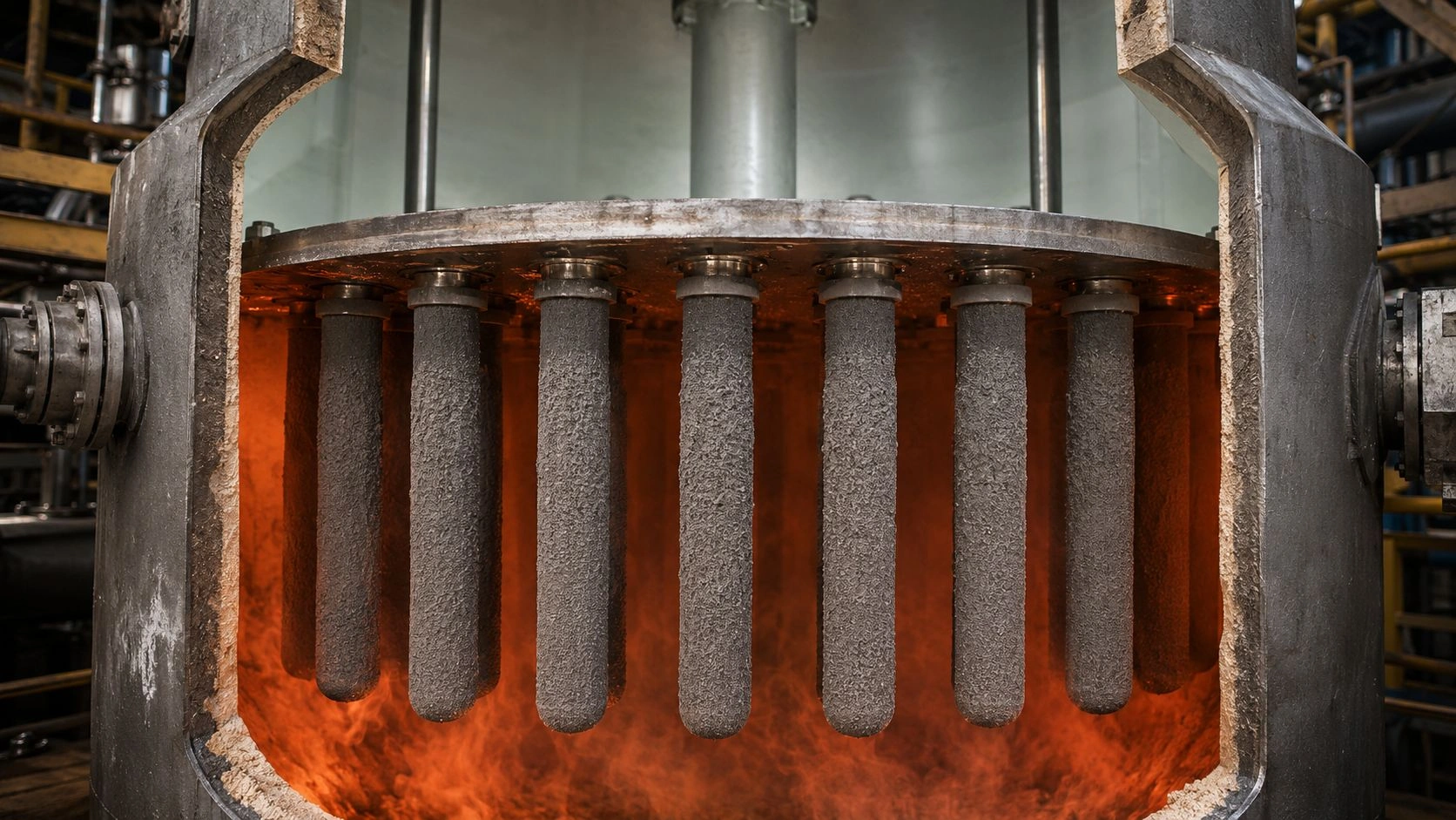
Porous SiC candle filters remove hot particulate-laden gas by outside-to-inside flow — dust cake forms on the outer surface and is released by periodic back-pulse cleaning. The specification must address pore structure, face velocity, dust chemistry, and thermal shock from cleaning cycles.
This article is part of ADCERAX's coverage of silicon carbide tubes for high-temperature, corrosive, and process applications, which includes dense SSiC and RBSiC grades for protection tube and process-tube service alongside the porous SiC ceramic category for filtration and flow-control applications.
What "SiC tube" means in high-temperature gas filtration
The most important disambiguation for this topic is that a SiC tube used in gas filtration is a fundamentally different component from a dense SiC protection tube or heat-exchange tube. Understanding this distinction prevents the most common specification error: purchasing a dense SiC tube and expecting it to filter particulate gas.
The Dense vs Porous SiC Tube comparison below maps the two product categories:
| Tube type | Best-fit use | Main advantage | Main limitation |
|---|---|---|---|
| Dense SSiC tube | Protection tube, thermowell, gas guide, corrosion sleeve | Low porosity and high chemical resistance | Does not filter particulates |
| Dense RBSiC/SiSiC tube | Larger hot-zone structural tube | Good thermal shock and shape capability | Residual silicon and porosity boundary |
| Porous SiC tube | Hot gas filtration, dust removal, gas permeability | Controlled flow and particle capture | Needs pore/membrane/cleaning design |
| SiC membrane candle | Fine particulate removal with support tube | High filtration efficiency with manageable pressure drop | Membrane damage or plugging risk |
| Segmented SiC filter element | Large systems or replaceable modules | Easier installation and replacement | Joint sealing and alignment risk |
| SiC-coated support | Clean SiC surface on different structure | Combines support and surface function | Coating integrity and thermal mismatch |
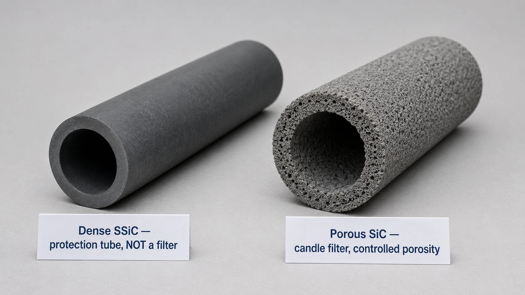
Dense SiC process tubes vs porous SiC filter tubes. A dense SSiC or RBSiC tube is manufactured to minimize open porosity — its value is in structural integrity, thermal conductivity, and chemical resistance at the tube wall. Gas cannot flow through the wall; the tube guides or contains the gas stream. A porous SiC filter tube is engineered with controlled open porosity through the wall and, typically, a membrane layer of finer pores on the outer surface. Gas flows radially through the wall from outside to inside, leaving particles behind as a dust cake.
Candle filter geometry: dirty gas outside, clean gas inside. Published patent literature on ceramic hot-gas candle filters describes the classic candle geometry: the hot dirty gas enters the filter vessel, contacts the outer surface of the tubular candle elements, and passes through the porous wall from outside to inside. Particulate matter forms a dust cake on the outer surface. The cleaned gas exits through the hollow center channel of the candle. The candle bottom is typically closed; the open top connects to the clean-gas plenum. This geometry is what makes back-pulse cleaning effective — a brief reverse-flow pulse of clean gas from inside to outside dislodges the dust cake, which falls into the collection hopper below.
Dust cake formation and why back-pulse cleaning is required. As filtration continues, the dust cake grows thicker and the pressure drop across the filter element rises. Without periodic cleaning, the pressure drop eventually exceeds the design limit and flow rate drops below the process requirement. Back-pulse cleaning — a brief pulse of compressed clean gas injected from the clean side — reverses the pressure gradient, fractures the dust cake, and releases it. The efficiency of cake release depends on pulse pressure, pulse duration, pore structure of the support layer, and the adhesion characteristics of the dust.
Why pore structure matters more than bulk SiC strength alone. The ORNL ceramic filter technology description confirms that in candle filter design, gas passes through the porous material and impurities form a cake on the outside. The pore structure — not the bulk ceramic strength — controls filtration efficiency and pressure drop. SiC's value in this application is that it provides a thermally and chemically stable pore structure that maintains both its geometry and its surface characteristics under the conditions of hot gas filtration.
The filter design variables that control performance
After confirming that a porous SiC filter candle is the correct product form, the specification must address the engineering variables that determine whether the filter will achieve the required efficiency, maintain an acceptable pressure drop, survive the cleaning cycle, and sustain the chemical environment of the gas stream.
[CITE: Published research on porous SiC hot gas filters confirms that support pore size, membrane layer, and back-pulse cleaning behavior are the controlling design variables — with higher support porosity improving back-pulse cleaning efficiency while finer membrane pore size increases fine-particle capture — and that SiC membrane candle filters tested on industrial coal-fired flue gas achieved 99.98% fly-ash rejection with pressure drop below 2700 Pa, while identifying flap and flange strength as a service-life limiting factor that requires optimized mechanical design alongside pore-structure specification.]
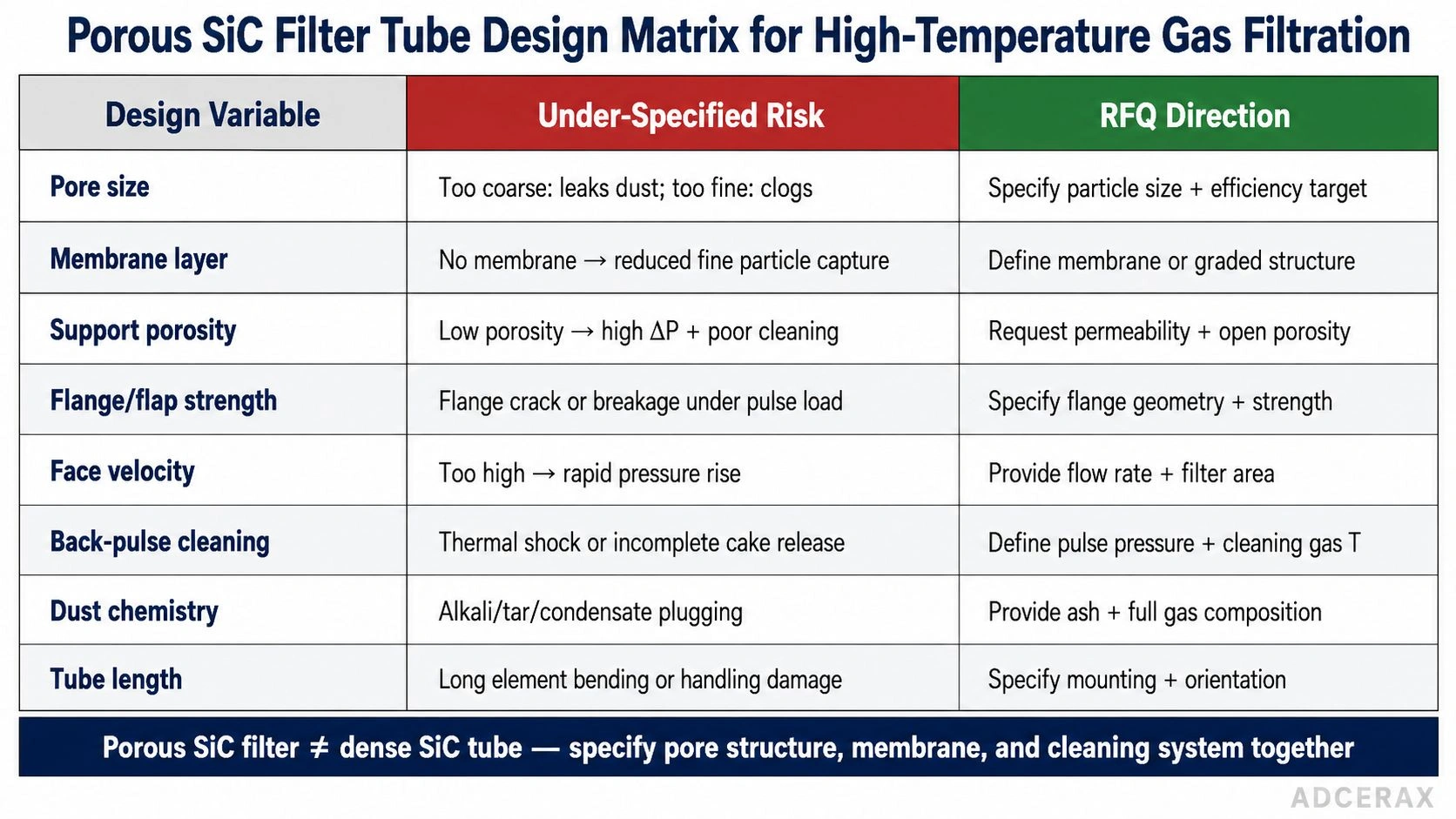
The Filter Design Matrix below maps each design variable to its functional role:
| Design variable | Why it matters | Under-specified risk | RFQ direction |
|---|---|---|---|
| Pore size | Controls capture and pressure drop | Too coarse leaks dust; too fine clogs quickly | Specify particle size and efficiency target |
| Membrane layer | Captures fine particles | No membrane may reduce fine capture | Define membrane or graded structure |
| Support porosity | Controls permeability and cleaning | Low porosity increases pressure drop and poor cleaning | Request permeability and open porosity |
| Flange/flap strength | Supports hanging candle load and pulse stress | Flange cracking or breakage | Specify flange geometry and strength |
| Face velocity | Controls pressure drop and cake formation | Rapid pressure rise | Provide flow and filter area |
| Back-pulse cleaning | Removes dust cake | Thermal shock and incomplete cleaning | Define pulse pressure and cleaning gas |
| Dust chemistry | Controls corrosion and stickiness | Alkali/tar/condensate plugging | Provide ash and gas composition |
| Tube length | Controls area and mechanical stress | Long element bending/handling damage | Specify mounting and orientation |
Values are qualitative; verify with gas-stream-specific dust testing, supplier filter data, and pilot-system trials.
Membrane pore size vs support pore size. A well-designed SiC candle filter is a composite structure: a coarser-pore support tube provides mechanical strength and most of the wall thickness, while a finer-pore membrane or coating layer on the outer surface provides the primary filtration. The support pore size is chosen to be large enough for good permeability and back-pulse cleaning, while the membrane pore size is chosen to capture the target particle fraction. Making the support too dense to improve filtration efficiency defeats the purpose — it raises pressure drop, makes cleaning harder, and reduces filter life.
Pressure drop and face velocity. Face velocity — the superficial gas velocity at the filter surface — is the primary design parameter that controls pressure drop across a clean filter. As face velocity increases, both the initial pressure drop and the rate of dust-cake growth increase. For a given filtration application, the face velocity is determined by dividing the total gas flow by the total external filter area. If face velocity is too high for the design's back-pulse cleaning capability, the pressure drop will rise faster than the cleaning system can control it.
Dust cake release and back-pulse cleaning. Effective back-pulse cleaning depends on the pulse pressure being high enough to fracture and dislodge the cake, the support porosity being open enough to allow the reverse flow, and the dust cake not being adhesive enough to resist release. If the gas stream contains tar, alkali condensate, or sticky fine ash, the dust cake may not release cleanly even with aggressive back-pulse parameters — which requires either modifying the process conditions or selecting a filter with a different surface chemistry or geometry.
Flange and flap strength and hanging load. SiC candle filters are typically suspended vertically from a tubesheet at their upper flanged end. The flange must support the weight of the candle body — which can be significant for 1500 mm long elements — as well as the mechanical impulse load from each back-pulse cleaning cycle. Published 2022 research on SiC membrane candle filters for coal-fired flue gas specifically identified flap and flange strength as a service-life-limiting factor and described optimized flap geometry as a design solution.
Why SiC is chosen over oxide ceramic or metal filters
After establishing what a porous SiC filter candle is and how it is specified, the material selection question is why SiC rather than porous mullite, porous alumina, sintered metal, or ceramic fiber composite elements.
SiC is considered when the filter must withstand temperature, corrosive chemistry, dust abrasion, and thermal shock at levels that exceed the capability of porous oxide ceramics or porous metals. Published product documentation from a porous SiC filter supplier describes porous reaction-bonded SiC filters as offering stability in corrosive applications, outstanding thermal shock and creep resistance above 1000°C, and higher temperature capability than porous metal and glass-bonded ceramics. Published filter geometries for hot-gas candle service include lengths up to 1500 mm.
High-temperature stability and creep resistance. Porous oxide ceramics such as mullite and cordierite have lower use temperatures and can creep or soften at the temperatures encountered in coal gasification, incinerator exhaust, or high-temperature combustion off-gas filtration. Dense graphite and sintered metal elements have higher temperature capability but can oxidize in certain gas chemistries. Porous SiC provides a combination of high-temperature capability, creep resistance, and chemical stability that positions it for the most demanding hot gas filtration environments.
Thermal shock resistance during startup and cleaning. The back-pulse cleaning cycle subjects the filter candle to a brief but significant thermal shock: the cleaning gas, even if preheated, is at a different temperature from the filter surface, and the rapid pressure and flow reversal creates a thermal transient. SiC's high thermal conductivity and thermal shock resistance — significantly better than most oxide ceramics — help it survive these repeated thermal events without progressive crack accumulation.
Corrosive gas and fly-ash exposure. In coal-fired flue gas and gasification gas streams, the filter is exposed to SOx, HCl, H₂S, alkali vapors, and reactive ash species. SiC forms a protective surface oxide in oxidizing conditions and maintains chemical stability in most reducing and mildly corrosive gas streams. The gas chemistry and ash composition must be reviewed against the specific SiC bonding route — sintered SiC, reaction-bonded SiC, or nitride-bonded SiC have different secondary-phase content and corrosion behavior.
The silicon carbide porous ceramic at ADCERAX — positioned for filtration and flow-control applications — represents the porous SiC route for these applications. The silicon carbide ceramic material grades — SSiC, RBSiC, and NBSiC — provide the material context for understanding how bonding phase and porosity affect filtration and corrosion performance.
Do not misdiagnose clogging, cracking, or pressure rise as "bad SiC"
When a porous SiC filter system shows rising pressure drop, declining filtration efficiency, candle cracking, or shortened service life, the immediate assumption is often that the SiC material quality is the problem. In most cases, the root cause is a system-design or process-chemistry issue.
Pressure drop increase: dust cake, pore plugging, or face velocity. Rapid pressure drop increase in a porous SiC filter is most commonly caused by incomplete dust cake release during back-pulse cleaning, not by degradation of the SiC pore structure. If the cleaning cycle is not aggressive enough, if the pulse frequency is too low, or if the dust is adhesive due to condensate or alkali content, the cake rebuilds faster than it is removed. Increasing pulse pressure, increasing pulse frequency, preheating the cleaning gas, or treating the dust upstream to reduce stickiness resolves these issues without changing the SiC material.
Back-pulse cracking vs poor SiC quality. Candle cracking that correlates with cleaning cycle events — particularly cracking at the flange, near the top connection, or along stress-concentration lines — is a thermal shock or mechanical shock failure from the cleaning pulse, not a bulk SiC quality defect. Published patent literature on ceramic hot-gas candle filters specifically warns that back-pulse cleaning introduces significant thermal stresses and can cause catastrophic failure if the cleaning gas temperature or pulse parameters are not matched to the filter design. Reducing pulse pressure, preheating the cleaning gas, or modifying the pulse duration resolves this failure mode.
Alkali, tar, condensate, and sticky ash effects. Gas streams from biomass gasification, municipal solid waste incineration, or certain industrial processes may contain alkali vapors, tars, or condensable species that form a strongly adhesive cake layer or penetrate the membrane pore structure. These species can irreversibly plug the filter even if the SiC material itself remains chemically stable. Gas chemistry and temperature must be confirmed against the dew points of all condensable species before the filter is specified — a filter operating above the tar or alkali dew point is in a different regime from one that sees liquid-phase deposits.
The Failure Diagnosis Matrix below maps common hot gas filter problems to better diagnostic questions:
| Observed problem | Common assumption | Better diagnostic question |
|---|---|---|
| Pressure drop rises quickly | SiC pore quality is poor | Is dust cake releasing during back-pulse cleaning? |
| Outlet dust increases | SiC material failed | Is membrane cracked, seal leaking, or pore size too large? |
| Candle cracks at flange | SiC too brittle | Is flange design or mounting stress too high? |
| Filter clogs after cleaning | Wrong SiC grade | Is support porosity too low or dust sticky/condensable? |
| Thermal crack after pulse | Bad ceramic | Is cleaning gas too cold or pulse pressure too aggressive? |
| Surface corrosion | SiC incompatible | Are alkali, HCl, H₂S, SOx, or molten ash present? |
| Short service life | Supplier quality issue | Was pilot dust/gas chemistry tested before full-scale use? |
Diagnosis should be based on pressure-drop trends, cleaning efficiency records, gas chemistry logs, and post-run candle inspection before any material specification is changed.
RFQ checklist for SiC tubes in high-temperature gas filtration
A complete RFQ for porous SiC filter tubes in high-temperature gas filtration must provide the complete gas-stream and dust-chemistry context — without it, the supplier cannot confirm pore-structure design, membrane requirement, bonding-phase selection, or pilot-test recommendation.
[CITE: Engineering guidance on porous SiC candle filter specification for hot gas filtration confirms the complete RFQ sequence: gas source, temperature and pressure with thermal cycling profile, dust load and particle size distribution, gas chemistry including SOx/NOx/HCl/H₂S/alkali/tar/condensate and dew point, flow rate and target face velocity, filtration efficiency requirement with outlet concentration limit, maximum allowable pressure drop and initial pressure drop, back-pulse parameters including pressure/frequency/cleaning gas temperature, tube geometry including OD/ID/length/wall/flange/end configuration, required pore size and membrane layer, and pilot-test request with representative dust and gas chemistry — because each of these variables can independently change whether a porous SiC candle filter is appropriate and which pore/bonding/membrane combination is most durable, and a supplier who receives only "SiC tube for hot gas filtration" cannot confirm pore design, cleaning compatibility, or corrosion resistance without the remaining system context.]
| RFQ field | Why it matters | Recommended wording |
|---|---|---|
| Gas source | Defines chemistry and dust | "Coal flue gas/biomass gas/incinerator/furnace exhaust" |
| Temperature and pressure | Defines service boundary | "Continuous, peak, pressure, thermal cycle" |
| Dust load | Controls cake growth | "g/Nm³ or mg/m³ inlet dust concentration" |
| Particle size | Controls pore and membrane design | "D10/D50/D90 or target particle capture size" |
| Gas chemistry | Controls corrosion | "SOx, NOx, HCl, H₂S, alkali, moisture, tar, dew points" |
| Flow/face velocity | Controls pressure drop | "Total flow, filter area, target face velocity" |
| Pressure drop limit | Defines operation window | "Initial and maximum allowable ΔP" |
| Cleaning method | Controls life and thermal shock | "Back-pulse pressure, frequency, gas temperature" |
| Tube drawing | Controls fit and stress | "OD, ID, length, wall, flange, closed/open end" |
| Filter structure | Core performance | "Porosity, pore size, membrane layer, permeability" |
| Validation | Confirms real performance | "Pilot test with representative dust and gas chemistry" |
RFQ fields are the minimum for a porous SiC candle filter inquiry; add orientation (vertical/horizontal), number of elements, replacement access method, and inspection frequency as needed.
For critical hot-gas filtration applications — coal gasification, high-dust industrial exhaust, or chemically aggressive incinerator gas — pilot testing with representative gas and dust chemistry is the only reliable qualification method. Room-temperature air-permeability data confirms pore structure but does not predict filter behavior with real sticky dust, alkali condensate, or high-temperature thermal cycling. The ceramic tubes and pipes cross-material range across SiC, alumina, zirconia, and BN illustrates how the same process-condition questions that govern porous SiC filter selection also apply to dense ceramic tube selection in adjacent hot-gas applications.
Evaluating porous SiC tubes or candle filters for high-temperature gas filtration? Share your gas source, temperature, pressure, dust loading, particle size distribution, gas chemistry, flow rate, pressure-drop limit, back-pulse parameters, and tube drawing. ADCERAX can review whether porous SiC, membrane-coated SiC, dense SiC protection tubes, or another ceramic route fits the application; turnaround depends on inquiry complexity — no commitment required at this stage.
Frequently Asked Questions
Are SiC tubes used for high-temperature gas filtration?
Yes, but they must be porous SiC filter tubes or candle filter elements — not dense SiC process tubes. Dense SiC tubes are appropriate for thermocouple protection, gas guiding, and hot-zone structures, but they do not filter particulate matter unless specifically engineered with controlled open porosity and a membrane layer. The specification must confirm porous candle filter geometry, not dense tube geometry.
Why is SiC used for hot gas candle filters?
SiC offers a combination of high-temperature capability, thermal shock resistance, creep resistance, and corrosion resistance that exceeds porous metal elements and many oxide ceramics in demanding hot gas filtration environments. Published porous SiC filter data positions reaction-bonded SiC candles for corrosive hot-gas applications with thermal shock and creep resistance above 1000°C.
What filtration efficiency can porous SiC candle filters achieve?
Published research on SiC membrane candle filters applied to industrial coal-fired flue gas reported 99.98% fly-ash rejection with a pressure drop below 2700 Pa under tested conditions. Actual performance depends on pore design, membrane layer, face velocity, dust chemistry, and cleaning system effectiveness.
Is a smaller pore size always better for hot gas filtration?
No. Smaller pore sizes can improve fine-particle capture but increase initial pressure drop and make back-pulse cleaning harder, reducing filter life. Hot gas filter designs typically use a coarser-pore support tube for permeability and cleanability, combined with a finer-pore membrane layer for efficient particle capture — balancing capture efficiency against pressure-drop and cleaning performance.
Why do porous SiC candle filters crack?
Cracking is most commonly caused by back-pulse thermal shock — the cleaning pulse introduces a rapid temperature and pressure reversal that creates tensile stress in the ceramic wall, particularly near the flange. Published ceramic hot-gas filter patent literature specifically identifies back-pulse cleaning as a source of significant thermal stress and a potential cause of catastrophic failure. Reducing pulse pressure, preheating the cleaning gas, or modifying pulse frequency typically resolves cracking without changing the SiC material.
What information should I send to a supplier for porous SiC filter tubes?
Send the gas source and temperature profile, operating pressure, dust loading in g/Nm³ or mg/m³, particle size distribution, complete gas chemistry including SOx/NOx/HCl/H₂S/alkali/tar/moisture and estimated dew points, total gas flow and target face velocity, filtration efficiency requirement and outlet concentration limit, maximum allowable pressure drop, back-pulse parameters, tube drawing with OD/ID/length/flange/end design, required pore size or membrane specification, and whether a pilot test with representative dust and gas is needed before committing to production quantities.