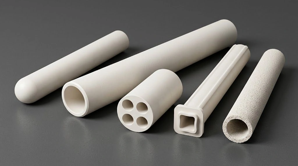
Alumina Rod failures in corrosive fixtures often start quietly as residue buildup or edge chipping; small defects can escalate into misalignment, leakage paths, and premature replacement.
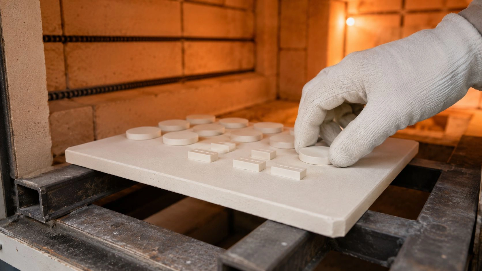
In chemical-processing fixtures, treat the rod as a structural part — spacer, guide, or isolator — and set media and CIP boundaries first, then geometry, clearance, surface finish, and wear-limit checks before locking an RFQ.
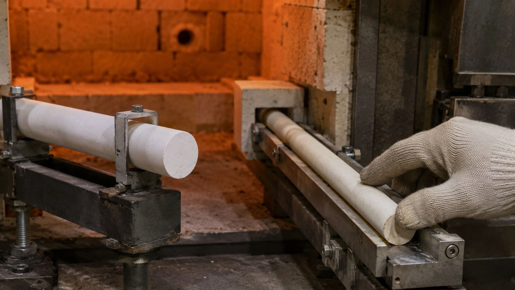
Many plants face compound duty: slurry abrasion, hot alkaline cleaning, and thermal cycling in one assembly. The framework below keeps those duty fields explicit so the rod can be drawn and quoted without generic corrosion claims.
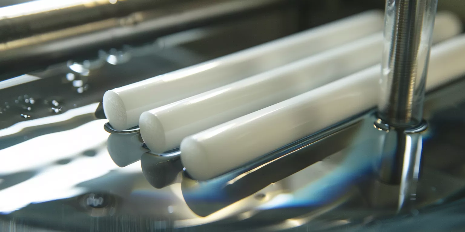
Before chemical compatibility is discussed, Alumina Rod use must be anchored in the real fixture functions that drive loading, exposure, and cleaning. Once a rod becomes a spacer, guide, or isolator, it must hold geometry and surface integrity under corrosive media and routine maintenance.
Alumina Rod as a Structural Material in Chemical Equipment
Alumina Rod selection for chemical processing fixtures begins with structural function, because the same ceramic behaves differently as a spacer, guide rod, or support pin.
Alumina Rod is widely treated as a simple ceramic stock, yet in chemical equipment it becomes a structural element that constrains alignment, clearance, and contact pressure. Many fixtures operate inside mixed conditions where corrosive liquids, abrasive solids, and repeated cleaning intersect, so performance depends on more than basic material inertness.
In practice, the most common applications include support posts for liners, spacer rods for pump and valve fixtures, guide rods for agitator accessories, and insulating separators that prevent galvanic or crevice corrosion at metal interfaces. For example, in a slurry sampling station, a guide rod held positional repeatability through repeated cycles only after end edges were protected and surface finish was tightened to reduce residue adhesion.
Therefore, the structural identity of an Alumina Rod in a chemical fixture must be specified in terms of load path, contact interfaces, and exposure pattern. Media compatibility and cleaning strategy can then be evaluated with the correct boundary conditions rather than generic corrosion claims.
Summary Table: Typical Structural Uses of Alumina Rods in Chemical Fixtures
| Fixture Function | Typical Contact Mode | Dominant Exposure | Primary Risk |
|---|---|---|---|
| Spacer and standoff | Compression between metal parts | Acid or alkali splash | Edge chipping and stress concentration |
| Guide rod and locator | Sliding or intermittent contact | Slurry and particulate | Abrasion-driven diameter loss |
| Support post for liners | Static load with occasional shock | Mixed chemicals and rinse cycles | Microcracking from assembly constraint |
| Insulating separator | Light load, high cleanliness | Solvents and condensate | Residue adhesion and surface leakage |
With fixture function fixed, chemical stability becomes a media- and CIP-field exercise rather than a blanket corrosion claim.
Chemical Stability Across Corrosive Media
Alumina Rod performance in chemical processing fixtures depends on sustained chemical stability, because prolonged exposure can gradually alter surfaces, interfaces, and structural reliability.
Chemical stability is often assumed for alumina ceramics; however, real chemical processing environments impose continuous exposure, temperature coupling, and concentration gradients that amplify minor reactions. Compatibility must be evaluated against specific media classes rather than broad corrosion resistance claims.
In many plants, Alumina Rods operate in contact with process fluids across long campaigns, including cleaning cycles. Even slow surface change can influence residue adhesion, friction behavior, and microstructural integrity over time.
Acid Resistance Under Continuous Exposure
Alumina Rods generally resist most inorganic acids under moderate duty. Acid immersion stability is duty-specific — qualify on the drawing and media list rather than treating any immersion hour or mass-change band as a plant guarantee.
Hot concentrated acids can roughen surfaces and promote residue retention during later rinses even when bulk strength appears unchanged. State acid identity and temperature on the RFQ so finish and inspection criteria match the duty.
Engineers typically keep acidic fixtures within the temperature and concentration window on the drawing, and optimize post-processing surface finish to mitigate secondary fouling rather than assuming zero corrosion loss.
Alkali Exposure and High Temperature Interaction
Alkaline environments are a more restrictive boundary for Alumina Rod applications. Dilute alkalis at ambient conditions are often manageable; hot alkaline CIP accelerates etching — control exposure and finish, and state chemistry on the RFQ.
Etching rarely causes immediate fracture; instead it can gradually reduce dimensional precision and increase friction at contact points. In alkali-dominant processes, place rods in shielded or intermittently exposed locations, or tighten cleaning temperature controls to preserve geometry.
Solvent and Mixed Chemical Environments
Many organic solvents are acceptable for ambient immersion — confirm solvent identity and temperature on the drawing. Do not treat solvent identity alone as a free pass when trace acids or alkalis can ride into surface microfeatures.
Mixed environments add complexity: solvent systems carrying reactive species can stain or retain residue even when bulk mechanical properties look unchanged. Evaluate contaminant content and cleaning frequency together with the solvent.
Summary Table: Chemical RFQ Fields for Alumina Rod Fixtures
| RFQ Field | What to State | Why It Matters |
|---|---|---|
| Media | Acid / alkali / solvent / mixed; identity | Sets chemical attack mode |
| Concentration | Process and CIP chemistry | Separates dilute splash from CIP etch |
| Temperature | Process T and cleaning T | Hot duty drives etching and roughening risk |
| CIP / SIP | Frequency, alkaline or acid clean | Often harsher than steady process exposure |
| Finish / inspection | Target Ra, edge treatment, wear check | Links chemistry to geometry retention |
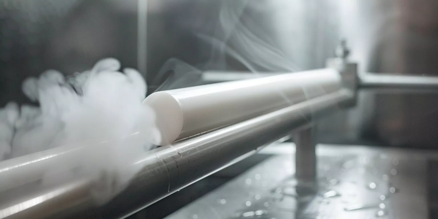
Before chemical resistance can be considered sufficient, Alumina Rods must also withstand mechanical loading inside fixtures that operate continuously in corrosive environments. Structural integrity under combined chemical and mechanical stress becomes a decisive factor.
Mechanical Integrity in Corrosive Processing Fixtures
Alumina Rod reliability in chemical processing fixtures depends on mechanical integrity, because corrosive exposure often amplifies stress sensitivity under static and dynamic loading.
In chemical equipment, Alumina Rods rarely experience purely static conditions. Instead, they function as load-bearing spacers, guides, or supports subjected to vibration, intermittent impact, and thermal expansion mismatch. Mechanical behavior must be evaluated together with chemical exposure rather than as an isolated property.
In practice, many premature failures attributed to “chemical attack” are traced back to stress concentration and improper load transfer. Understanding how Alumina Rods carry load within fixtures clarifies realistic design limits.
Load Bearing Behavior in Support and Spacer Applications
Alumina Rods used as spacers or supports typically operate under compressive stress. Typical compressive strength is about ~2000–2900 MPa by grade (TDS screening) — not a fixture allowable. Design from geometry, support, and purchase-order limits rather than a single blanket compressive claim.
Real assemblies rarely distribute load uniformly. Misalignment at contact edges can amplify local stress and initiate microcracking after repeated thermal cycles even when bulk fracture does not occur immediately.
Even when compressive screening capacity looks ample, control load distribution and contact geometry to prevent stress amplification.
Bending and Fracture Risk in Fixture Design
Slender Alumina Rods are particularly vulnerable to bending loads introduced by fixture geometry. Side load on long unsupported spans is a common route to vibration-driven fracture.
Minimize unsupported span and avoid using Alumina Rods as cantilevered elements in corrosive environments. Shortening span or adding intermediate support is often more effective than changing material grade.
Stress Concentration From Assembly Constraints
Assembly practices often introduce hidden stress. Over-tightened fasteners, rigid metal housings, or insufficient clearance for thermal expansion preload Alumina Rods beyond safe limits.
Avoid high preload; allow expansion; control assembly torque. Chemical exposure further accelerates crack propagation along stressed regions.
Summary Table: Mechanical Integrity Factors in Corrosive Fixtures
| Mechanical Factor | Engineering Practice | Observed Risk if Ignored |
|---|---|---|
| Contact alignment | Control seating and edge contact | Local stress → microcrack initiation |
| Side load on slender rods | Minimize lateral load paths | Bending fracture risk |
| Unsupported span | Shorten span or add support | Vibration sensitivity |
| Assembly preload | Limit clamp load; allow expansion | Higher fracture incidence in service |
| Compressive screening (TDS) | ~2000–2900 MPa by grade; ≠ allowable | Over-trusting datasheet vs geometry |
As chemical processing shifts from clear liquids to particle-rich media, Alumina Rod durability increasingly depends on resistance to abrasion and erosive contact. Wear behavior becomes as critical as chemical inertness.
Wear Resistance in Slurry and Particle Laden Systems
Alumina Rod service life in chemical processing fixtures is strongly influenced by wear resistance, because slurry flow and suspended particles impose continuous abrasive interaction.
In slurry transport, filtration, and mixing equipment, Alumina Rods frequently serve as guides, spacers, or alignment pins exposed to moving solids. Abrasion rarely occurs uniformly; localized particle impingement and sliding contact gradually reshape critical dimensions. Evaluate wear as geometry retention rather than hardness alone.
Fixtures exposed to fine mineral slurries often show measurable wear long before chemical attack becomes visible. Defining particle, velocity, and wear-limit fields on the maintenance plan supports predictable replacement.
Abrasive Wear in Slurry Transport and Mixing
Alumina Rods benefit from high hardness — typically Mohs ~9 (TDS), or hardness per an agreed method on the drawing — which supports abrasion resistance against fine particles. Do not treat a single HV band as a contract hardness for wear life.
Wear rate rises with particle angularity and velocity. Angular particles can groove contact faces and drift fixture alignment even when structural failure does not occur. Include particle morphology and flow regime in wear assessments.
Surface Degradation and Dimensional Stability
Surface wear directly affects dimensional stability in fixtures requiring precise alignment. Even minor diameter loss can alter clearance, leading to vibration or secondary contact damage elsewhere in the assembly.
Worn surfaces also tend to trap residues, compounding abrasive effects during cleaning cycles. Specify tighter initial tolerances or protective finishing when rods will see abrasive chemical duty, and define a wear/play limit on the maintenance plan.
Summary Table: Wear RFQ / Plan Fields for Slurry Service
| Plan Field | What to State | Why It Matters |
|---|---|---|
| Hardness method | Mohs ~9 (TDS) or agreed method | Avoid uncontracted HV as life guarantee |
| Particle size / shape | Median size; angular vs rounded | Drives grooving vs polishing wear |
| Flow velocity | Typical and peak | Raises abrasive energy |
| Wear / play limit | Measurable diameter or clearance drift | Triggers inspection / replacement |
| Finish | Target Ra if fouling-critical | Links wear to residue traps |
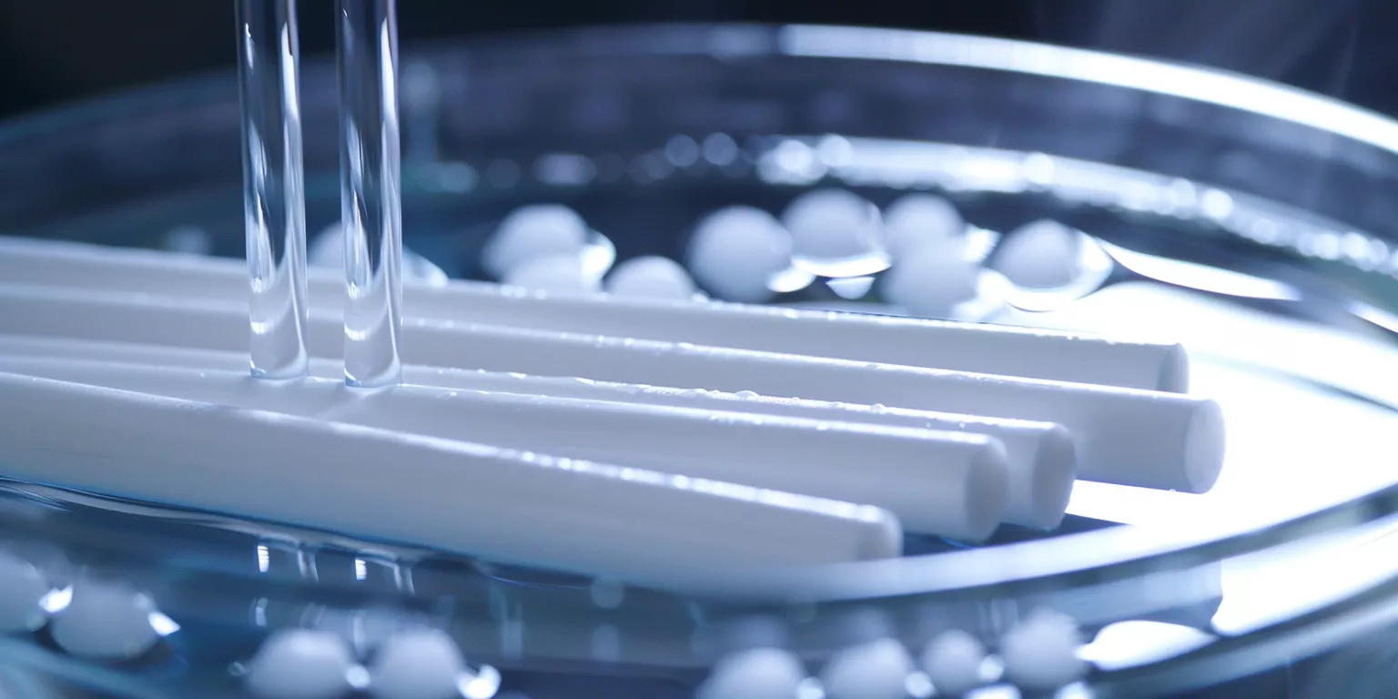
As routine operation alternates with aggressive cleaning and sterilization, Alumina Rods must tolerate repeated temperature swings without accumulating hidden damage. Thermal cycling compatibility becomes a key reliability filter.
Thermal Cycling and Cleaning Process Compatibility
Alumina Rod reliability in chemical processing fixtures depends on thermal cycling tolerance, because repeated heating and cleaning sequences impose expansion mismatch and shock stress.
Chemical plants frequently apply CIP and SIP procedures involving hot water, steam, or alkaline solutions. Fixtures then cool rapidly once cleaning ends. Alumina Rods experience repeated temperature gradients that can exceed those seen in steady-state processing.
Failures often occur not during operation but immediately after cleaning. Evaluating thermal cycling under realistic gradients is essential for long-term fixture stability.
Thermal Shock Resistance During Cleaning Cycles
Dense alumina exhibits moderate thermal shock resistance governed by elastic modulus and thermal conductivity. Thermal cycling plus sharp edges or constrained mounting raises crack risk — qualify geometry and mounting freedom rather than citing a cycle-count contract.
Most cracks originate at end faces or near contact interfaces rather than mid-span regions. Chamfered ends and free expansion paths improve survival compared with sharp, tightly clamped mounts.
Interaction With Steam and Hot Alkaline Cleaning
Steam cleaning introduces thermal and chemical stress together. Saturated steam does not typically chemically degrade alumina, but it promotes rapid temperature rise and condensation-driven gradients.
Hot alkaline CIP combined with thermal expansion can accelerate microdefect growth at the surface. Rods intended for frequent hot cleaning benefit from conservative temperature ramps, controlled mounting clearance, and refined surface finish.
Summary Table: Thermal / CIP Factors for Alumina Rods
| Factor | Engineering Practice | Risk if Ignored |
|---|---|---|
| Cleaning temperature swing | Control ramp; state CIP T on RFQ | Expansion-induced stress |
| Edge / mount geometry | Chamfer ends; avoid rigid clamp | Crack initiation at edges |
| Steam exposure | Allow condensation gradients | Gradient-driven cracking |
| Hot alkaline CIP | Limit exposure; refine finish | Accelerated surface damage |
Before selecting material grades or surface finishes, engineers must translate fixture requirements into practical rod geometry. Dimensional design governs whether Alumina Rods remain stable or become latent failure points.
Geometry Design for Chemical Processing Fixtures
Alumina Rod geometry in chemical processing fixtures directly controls stress distribution, wear progression, and cleaning reliability; dimensional discipline is as critical as material purity.
In chemical equipment, geometry determines how loads are transferred, how residues accumulate, and how thermal expansion is accommodated. Small geometric oversights often magnify under corrosive and abrasive exposure.
Diameter, length, end treatment, and tolerance must be specified as an integrated system rather than isolated dimensions.
Diameter and Length Selection for Fixture Stability
Rod diameter governs both stiffness and contact stress. Larger OD raises bending stiffness under the same side load; oversized rods can restrict cleaning flow and trap residues. Balance mechanical rigidity against flow accessibility and cleanability on the drawing.
End Geometry Chamfer Radius and Edge Protection
End geometry is a frequent origin of cracking and chipping. Sharp edges concentrate stress and promote microcrack initiation during assembly and thermal cycling.
Controlled chamfering or rounding is typical drawing practice for chemical fixtures — not cosmetic. Treat chamfer size as an RFQ/drawing field rather than a guaranteed damage-reduction percentage.
Tolerance Control in Assembly Interfaces
Tolerance determines how Alumina Rods interact with metal housings and clamps. Excessively tight fits introduce preload stress, while loose fits allow vibration and impact.
Radial clearance should be aligned with vibration spectrum, thermal expansion, and assembly method. State a typical clearance window on the RFQ; the drawing and PO govern.
Summary Table: Geometry Parameters for RFQ / Drawing
| Geometry Parameter | Typical Practice | Reliability Role |
|---|---|---|
| Rod diameter | Sized for stiffness vs cleanability | Deflection and fouling balance |
| Unsupported length | Keep spans short for side-load duty | Reduced bending risk |
| End chamfer | Illustrative inquiry window (e.g. ~1.0–1.5 mm) — drawing governs | Edge chip / crack control |
| Radial assembly clearance | Illustrative inquiry window (e.g. ~0.10–0.20 mm) — drawing governs | Stress and vibration balance |
| Length-to-diameter | Avoid overly slender cantilevers | Structural stability |
Even when geometry and material selection are correct, surface condition ultimately governs how Alumina Rods interact with chemicals, residues, and cleaning media. Surface integrity becomes a decisive factor for long-term fixture hygiene and stability.
Surface Condition and Contamination Resistance
Alumina Rod surface condition in chemical processing fixtures influences residue adhesion, cleaning effectiveness, and contamination risk; surface engineering directly affects operational reliability.
In chemical environments, surfaces act as the first interface between ceramic and process media. Microscopic surface features often dictate macroscopic behavior, including fouling rate and cleanability. Treat roughness and finishing methods as functional parameters rather than cosmetic attributes.
Rods with identical bulk composition but different surface finishes often show different maintenance intervals. Surface control is essential for predictable service life.
Surface Roughness and Chemical Residue Adhesion
Surface roughness strongly affects how chemical residues and precipitates adhere to Alumina Rods. If fouling is critical, state a target Ra on the drawing/RFQ — not as a guaranteed fouling-percentage reduction.
In slurry-contact fixtures, rough surfaces act as nucleation sites for particle agglomeration. Smoother finishes generally clean more readily; pick the Ra window from hygiene and motion requirements, not from unverified % claims.
Surface Finish for Repeated Cleaning Environments
Repeated CIP and SIP cycles amplify surface-related effects. Each cleaning cycle can either remove residues or drive them deeper into surface microfeatures, depending on finish quality.
Fine-ground finishes generally retain cleaner geometry under repetitive alkaline cleaning than coarse as-sintered surfaces. Fine finishing enhances cleanability and reduces cumulative surface degradation under repetitive cleaning.
Summary Table: Surface RFQ Fields
| Surface Parameter | Typical Practice | Note |
|---|---|---|
| Target Ra | State on drawing if fouling-critical (illustrative ≤0.6 µm window — drawing/PO governs) | Not a guaranteed fouling % |
| As-sintered / coarse | Higher fouling risk in slurry duty | May need grind/polish |
| CIP finish match | Align finish with alkaline/acid clean | Residue traps vs cleanability |
| Edge blend | With chamfer practice | Chip and fouling at ends |
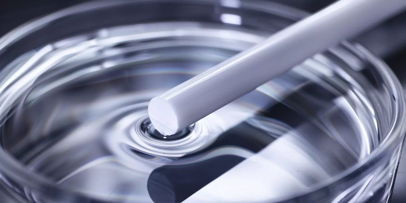
Despite careful material selection and controlled processing, failures still occur when Alumina Rods operate in chemically aggressive fixtures. Examining real failure modes clarifies where design and integration most often break down.
Failure Modes Observed in Chemical Processing Fixtures
Alumina Rod failures in chemical processing fixtures reveal how chemical exposure, mechanical stress, and geometry interact; failure analysis provides guidance for preventive design.
In chemical plants, failures rarely stem from a single cause. They develop through cumulative interaction between surface degradation, stress concentration, and operational cycling. Recognizing dominant failure pathways allows engineers to intervene before functional loss occurs.
Field investigations across reactors, mixers, and sampling systems consistently show repeatable patterns rather than random breakage.
Chemical Assisted Fracture and Degradation
Chemical assisted fracture occurs when corrosive media weaken surface bonds at stressed locations. Although alumina remains chemically stable in many environments, hot alkaline solutions or mixed media can accelerate crack growth at existing microdefects.
Hot alkaline CIP acting on preloaded contact edges is a common accelerant: chemistry reduces tolerance for assembly stress and thermal cycling rather than simply dissolving the bulk ceramic.
Combined Wear Corrosion Failure
Wear corrosion is a synergistic mechanism where abrasion removes surface layers and chemicals reach newly exposed microstructure. This effect is especially pronounced in slurry-handling fixtures.
Evaluate wear and corrosion together; isolated lab tests often underestimate real fixture degradation. Progressive diameter or play loss is a typical onset indicator — define the limit on the maintenance plan.
Summary Table: Common Failure Modes of Alumina Rods in Chemical Fixtures
| Failure Mode | Primary Trigger | Typical Onset Indicator |
|---|---|---|
| Edge chipping | Assembly stress and sharp geometry | Visible microcracks at ends |
| Chemical assisted fracture | Hot alkaline or mixed media | Crack growth at contact zones |
| Wear corrosion | Slurry abrasion plus cleaning | Progressive diameter loss |
| Thermal shock cracking | Rapid cleaning temperature change | Radial surface cracks |
| Residue-induced binding | Surface roughness and fouling | Restricted movement or seizure |
Integration with surrounding metalwork and seals determines whether these modes stay latent or become chronic. Assembly practice is the next control point.
Integration With Chemical Equipment Assemblies
Alumina Rod integration with chemical equipment assemblies determines whether geometry and material choices survive real mounting, sealing, and thermal expansion paths.
Even a well-specified rod can fail early if clamps, seals, and clearances fight thermal expansion or concentrate contact stress. Treat mating metals, preload, and alignment as RFQ fields alongside media and CIP.
Interaction With Metal Components and Seals
When Alumina Rods contact metal parts, differential thermal expansion creates cyclic interface stress. Alumina and stainless steel expand differently, which can preload rods during heating if the clamp path is rigid.
Use compliant seals or controlled contact pressure rather than rigid metal clamps that lock axial growth. Qualify the interface on the drawing instead of relying on unverified stress-percentage anecdotes.
Assembly Clearance and Alignment Considerations
Axial and radial clearance should match vibration, thermal expansion, and assembly method. State illustrative clearance windows on the RFQ; the drawing and PO govern. Outside a sensible window, fracture and wear risk rise — without needing a fabricated first-year failure percentage.
Summary Table: Assembly Integration Practices
| Integration Factor | Engineering Practice | Risk if Ignored |
|---|---|---|
| Metal CTE mismatch | Allow expansion; avoid rigid lock-up | Cyclic preload / crack initiation |
| Seal / clamp path | Compliant interface; controlled pressure | Edge stress concentration |
| Axial clearance | Illustrative RFQ window — drawing governs | Thermal bind or looseness |
| Radial clearance | Illustrative RFQ window — drawing governs | Vibration wear or pinch |
| Alignment | Seat contacts cleanly; protect edges | Local microcrack start |
Once integration practice is set, material alternatives can be compared on qualitative duty trade-offs rather than unverified life-month claims.
Comparison With Alternative Ceramic Materials
Alumina Rod selection in chemical processing fixtures is frequently compared with alternative ceramics, because corrosion, wear, and cost pressures drive material reassessment.
Alumina Rods are commonly evaluated against silicon carbide, zirconia, and mullite when fixtures operate under corrosive or abrasive conditions. Material substitution rarely delivers uniform improvement across all performance dimensions. Each alternative introduces a different balance of chemical stability, mechanical behavior, and manufacturability.
Silicon Carbide (SiC) offers strong hardness and abrasion resistance. In strongly alkaline hot service, SiC can see accelerated surface oxidation, and its higher stiffness increases sensitivity to assembly misalignment. In slurry fixtures, SiC may wear less but can show higher fracture incidence under vibration compared with alumina — treat as a qualitative trade-off, not a life-month contract.
Zirconia Ceramics provide higher fracture toughness, which improves resistance to mechanical shock. Zirconia can show reduced chemical stability in certain acidic and alkaline environments and phase-related property shifts with prolonged thermal cycling. Prefer drawing-specific chemical checks over unvetted month-count comparisons.
Mullite and Porous Ceramics deliver lower cost and lower thermal conductivity, yet their flexural strength is typically lower than dense alumina. They are rarely suitable for load-bearing chemical fixtures where alignment must be preserved.
Alumina Rods remain a balanced choice when chemical stability, dimensional control, and integration reliability must coexist within the same fixture.
After material selection is confirmed, chemical plants must plan how Alumina Rods will be maintained and replaced over long operating cycles. Maintenance strategy influences both uptime and fixture consistency.
Maintenance and Replacement Strategy in Chemical Plants
Alumina Rod use in chemical processing fixtures requires predictable maintenance planning, because replacement timing and dimensional consistency directly affect operational stability.
-
Planned Replacement Based on Wear and Exposure
Define the inspection interval and wear/play limit on the maintenance plan. Typical triggers are measurable diameter loss or increased play — not a fixed hour contract. Replacing on plan helps prevent secondary damage to metal housings and seals. -
Spare Part Consistency and Interchangeability
Consistent rod geometry and surface finish are critical for spare parts. Uncontrolled substitutes can introduce alignment deviation after replacement, leading to vibration and accelerated wear. Maintaining identical specifications across batches reduces commissioning risk. -
Scheduled Lifecycle Instead of Reactive Swap
Track exposure conditions and replace rods during planned shutdowns when wear limits are approached. This shifts maintenance from reactive to preventive, especially in corrosive environments where failure signals are subtle. Do not treat downtime-percentage claims as case proof.
Reliable maintenance planning depends on stable manufacturing quality and the ability to reproduce identical rods over multiple production cycles.
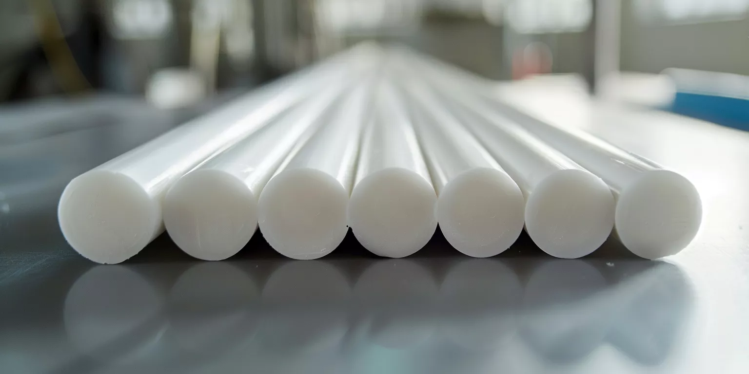
After lifecycle and maintenance considerations are clarified, many chemical equipment manufacturers recognize that standard Alumina Rods cannot fully resolve fixture-specific constraints. Geometry and finish options for RFQ become the next step.
Geometry & Finish Options for RFQ
Alumina Rod customization for chemical processing fixtures enables precise control of geometry, surface condition, and integration; tailored engineering supports long-term reliability.
Chemical processing fixtures rarely share identical operating conditions. Variations in media composition, temperature gradients, cleaning protocols, and assembly constraints demand application-specific Alumina Rod designs rather than generic stock components. Customization is a practical requirement for stable operation.
Start with fixture function rather than nominal dimensions. When a rod acts as a spacer near aggressive cleaning zones, chamfer geometry, surface roughness, and tolerance window should be optimized together. Illustrative inquiry windows (for example end chamfer and Ra targets) help RFQ conversation — the drawing and PO govern; do not treat life-multiplier claims as guarantees.
Review mating materials, assembly preload, and thermal expansion paths when setting clearance and finishing. Prefer stress-reducing geometry over marketing ROI percentages.
A practical workflow covers material selection, precision forming, controlled sintering, surface finishing, dimensional inspection, and batch-to-batch traceability so prototypes, production fixtures, and spares stay consistent.
For non-standard diameter, chamfer, Ra, or tolerance needs, use custom ceramic services with media/T/CIP and drawing fields filled. Stock and near-stock options remain available via alumina rods.
Summary Table: Illustrative RFQ Inquiry Windows (Drawing/PO Governs)
| Customization Aspect | Illustrative Inquiry Window | Engineering Role |
|---|---|---|
| Diameter tolerance (mm) | ±0.05–0.10 | Assembly stress control |
| End chamfer (mm) | 1.0–1.5 | Crack and chip reduction |
| Surface roughness Ra (µm) | ≤0.6 | Reduced residue adhesion |
| Length repeatability (mm) | ±0.10 | Fixture alignment stability |
| Batch consistency | Match drawing/PO inspection plan | Predictable maintenance |
After RFQ fields are clear, evaluate Alumina Rods as long-term structural elements rather than consumable ceramic parts.
Closing Perspective on Alumina Rods in Chemical Processing Fixtures
Ultimately, Alumina Rod performance in chemical processing fixtures reflects system-level decisions: material selection, geometry control, and integration discipline collectively shape operational reliability.
Alumina Rods succeed in chemical processing fixtures not because they are universally inert, but because their chemical stability, mechanical predictability, and manufacturability align with real plant constraints. When rods are treated as engineered structural components rather than generic ceramic stock, failure rates decline.
Across corrosive media, abrasive slurries, and repeated cleaning cycles, the most reliable installations share common traits: conservative geometry, controlled surface condition, and allowance for thermal and assembly freedom. Design intent should account for exposure history rather than nominal operating conditions alone.
In essence, Alumina Rods remain one of the few ceramic materials capable of delivering repeatable structural performance in chemically aggressive environments, provided that engineering discipline governs their specification and lifecycle management.
Conclusion
Alumina Rod reliability in chemical processing fixtures emerges from balanced design rather than isolated material properties; disciplined geometry, surface control, and integration determine long-term success.
To specify a chemical-processing fixture rod, send media / temperature / CIP chemistry, fixture function, OD × length, clearance, chamfer, target Ra, wear-limit / inspection plan, and mating materials with your drawing for an RFQ review.
FAQ
Q1: Can Alumina Rods withstand long-term exposure to both acids and cleaning chemicals?
Yes. Alumina Rods remain chemically stable in many acidic environments under moderate duty. Hot alkaline cleaning requires controlled exposure and optimized surface finish to preserve dimensional stability — state chemistry and temperature on the RFQ.
Q2: What causes Alumina Rods to fail prematurely in chemical fixtures?
Most failures result from stress concentration, improper assembly clearance, or combined wear–corrosion effects rather than direct chemical dissolution.
Q3: How often should Alumina Rods be replaced in slurry-handling equipment?
Define the inspection interval and wear/play limit on the maintenance plan. Typical triggers are measurable diameter loss or increased play, depending on particle size and flow velocity — not a fixed operating-hour contract.
Q4: Why is customization important instead of using standard Alumina Rod sizes?
Chemical fixtures impose unique load paths, cleaning cycles, and integration constraints. Matching geometry and surface control to those fields supports service life and reduces unplanned downtime.
Related reading
- Alumina rod reliability in electrical insulation applications — When the alumina rod is specified for electrical insulation reliability — voltage and creepage first, not corrosive CIP fixture wear.
- Alumina rod performance in high-temperature systems — When furnace temperature and thermal cycling dominate alumina rod life — a high-temperature axis, not chemical-fixture media control.
- Black alumina ceramic for chemical processing equipment — When the chemical-processing equipment path prefers black alumina components — a material/appearance axis beside ivory alumina rod fixtures.