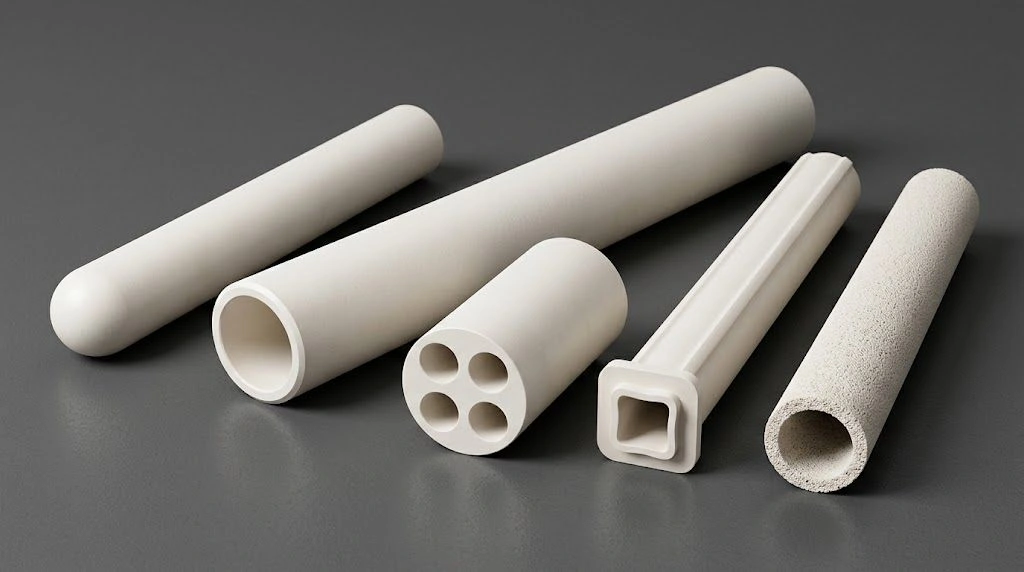
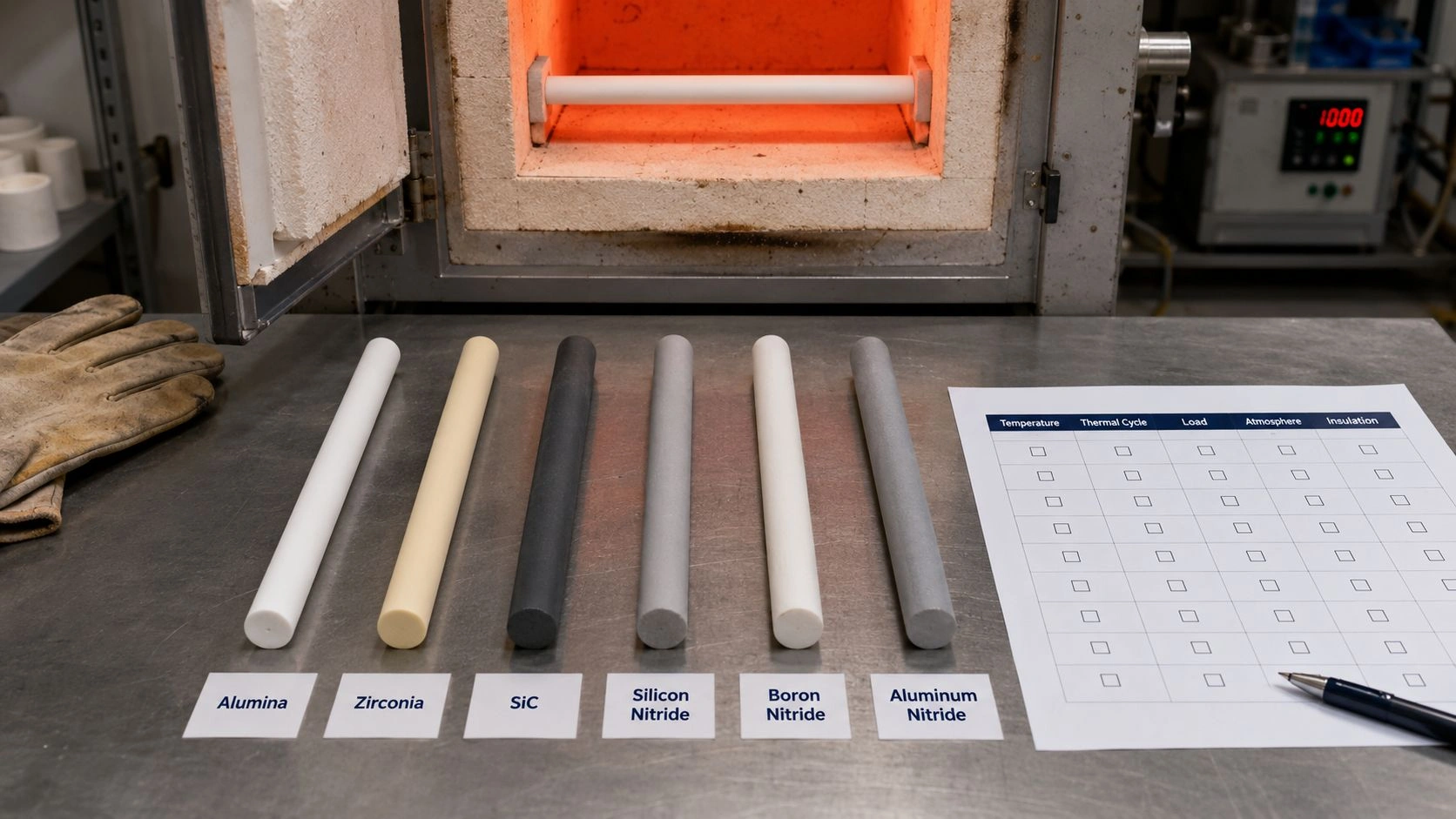
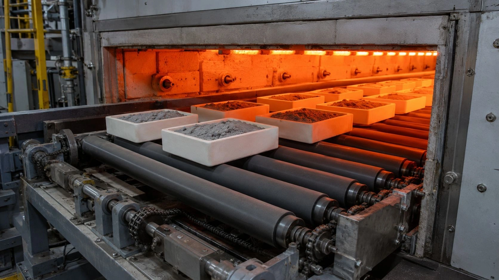
Alumina Substrate choices often surface when FR4 begins to saturate thermal headroom, insulation margins, or lifetime targets. Consequently, this comparison clarifies where performance risk accumulates and where design latitude remains.
This technical article aligns substrate physics with power density, dielectric stability, and lifecycle reliability. Moreover, it consolidates design constraints, manufacturing realities, and qualification logic for high-duty electronics.
Accordingly, the narrative moves from material fundamentals to system behavior under stress. Thereafter, it converges on selection criteria that engineers can defend during design-review and RFQ checklists.
Additionally, this overview anchors key trade-offs between Alumina Substrate and FR4 using repeatable engineering reasoning. Consequently, each section connects measurable properties to failure mechanisms that matter in power electronics and industrial deployments.
Why Substrate Choice Shapes Power Electronic Systems
Substrate selection sets the boundary conditions for heat, voltage, and strain in every power stage. Consequently, Alumina Substrate and FR4 decisions influence not only performance, but also failure probability over years of thermal cycling.
-
Thermal headroom becomes a system bottleneck
Power devices rarely fail because average board temperature looks high; instead, localized hotspots accumulate where the thermal path is weakest. Consequently, FR4 can appear acceptable in short validation runs yet drift in junction temperature during extended loads. In contrast, Alumina Substrate architectures usually suppress steep gradients, which stabilizes electrical parameters over long duty cycles. -
Electrical insulation evolves with temperature and time
Dielectric strength is not a static datasheet value once humidity, elevated temperature, and field stress coexist. Therefore, insulation aging can progress quietly until partial discharge or leakage becomes measurable. Moreover, Alumina Substrate platforms typically preserve dielectric stability across wider temperature bands than FR4 laminates under comparable stress. -
Thermomechanical strain accumulates into fatigue failures
Every power cycle imposes expansion mismatch between copper, solder, and the substrate body. As a result, fatigue damage concentrates at interconnects and metallization edges even when initial assembly quality is high. Furthermore, Alumina Substrate stiffness can reduce warpage-driven strain, while FR4 compliance can increase cyclic deformation once temperature approaches resin softening regimes.
Consequently, a substrate decision should be treated as a reliability architecture choice rather than a cost-only bill-of-material line item.
Material Foundations of Alumina and FR4
Material foundations establish the irreversible boundaries within which electrical, thermal, and mechanical behaviors evolve. Therefore, before performance metrics are compared, intrinsic material structure must be examined as the root cause of long-term stability or degradation. Moreover, alumina ceramics and FR4 composites differ fundamentally at the atomic and microstructural levels, which explains why their behaviors diverge under power and temperature stress.
Crystal ceramic architecture of alumina substrates
Alumina substrates are built upon a dense, polycrystalline aluminum oxide lattice, commonly in the 96% / 99.6% class used for substrates — confirm the ordered grade on the alumina grade sheet and drawing. This ceramic crystal framework forms a continuous solid with minimal internal phase boundaries.
In engineering practice, this structure delivers high isotropy, meaning thermal expansion, stiffness, and heat conduction remain consistent in all planar directions. During qualification, alumina substrates typically hold planar flatness better than polymer laminates under the same thermal-cycle envelope — quantify flatness and cycle count on the drawing rather than treating any published band as contractual endurance. Additionally, the absence of polymer phases eliminates softening or creep mechanisms that would otherwise amplify strain over time.
As a result, alumina’s crystal architecture provides a stable physical reference plane that resists both short-term thermal shock and long-term mechanical relaxation.
Glass fiber epoxy composite structure of FR4
FR4 substrates rely on a laminated composite of woven glass fibers embedded in epoxy resin, creating a heterogeneous material system by design. This layered construction enables cost-effective manufacturing but introduces directional dependencies and temperature-sensitive behavior.
Under moderate temperatures, glass fibers carry mechanical load while the epoxy matrix binds layers together. However, once operating temperatures approach the glass transition range of 130–170 °C, resin modulus drops sharply, and the composite’s effective stiffness decreases. In accelerated life testing, engineers frequently measure CTE values rising above 60–70 ppm/K beyond Tg, leading to progressive warpage and copper trace strain even when initial assembly quality is high.
Consequently, FR4’s composite nature embeds a temperature-dependent structural ceiling that cannot be removed through layout optimization alone.
Structural continuity versus layered heterogeneity
The contrast between alumina and FR4 ultimately reduces to structural continuity versus layered heterogeneity. Alumina behaves as a single, unified solid, while FR4 functions as a mechanically cooperative system of dissimilar phases.
In real-world evaluations, this difference becomes evident during long-duration thermal dwell tests. Alumina substrates typically show negligible permanent deformation after extended exposure at 200 °C, whereas FR4 assemblies often exhibit cumulative warpage that increases cycle-to-cycle strain at solder joints. Moreover, heterogeneous interfaces in FR4 act as stress concentrators, whereas alumina distributes stress more uniformly across its volume.
Therefore, the material foundation itself predetermines how stress accumulates and how reliably the substrate can serve as a long-term mechanical and thermal reference.
Summary of Material Foundation Differences
| Attribute | Alumina Substrate | FR4 |
|---|---|---|
| Primary Structure | Polycrystalline ceramic | Glass fiber epoxy composite |
| Purity / Composition | Commonly 96% / 99.6% class — confirm grade sheet | Glass fiber + epoxy resin |
| Young’s Modulus (GPa) | ~340–375 typical (grade sheet) | ~18–24 (laminate-dependent; not ADCERAX TDS) |
| Glass Transition Behavior | None | 130–170 °C |
| Structural Isotropy | High | Direction-dependent |
| Long-Term Dimensional Stability | Excellent | Degrades near Tg |
Thermal Transport Behavior Under Power Density Stress
Thermal transport defines whether electrical performance remains stable or drifts under sustained load. Therefore, substrate behavior must be evaluated under power density stress, not nominal operating temperatures alone. Moreover, alumina and FR4 manage heat through fundamentally different physical pathways, which causes divergence once localized dissipation intensifies.
Heat conduction paths in ceramic substrates
Alumina substrates conduct heat through a continuous crystalline lattice, enabling relatively uniform phonon transport across the substrate body. Consequently, thermal resistance remains predictable even when heat sources are highly concentrated.
In practical power-module layouts, alumina thermal conductivity is grade-dependent — typical values at 25°C on alumina grade sheets span about 18–42 W/(m·K) across purity bands (lower for ~95% class, higher toward 99.7–99.9% class). That lateral spreading path moves heat toward external sinks before hotspots deepen. In LED and power layouts, alumina often yields a lower device junction temperature than FR4 under the same drive current and airflow — quantify ΔTj on your thermal model rather than assuming a fixed °C delta. Furthermore, because ceramic lacks resin phases, thermal conductivity remains stable across wide temperature ranges rather than degrading near softening points.
As a result, alumina substrates transform localized heat into manageable gradients instead of permitting thermal accumulation beneath active devices.
Thermal bottlenecks inherent to FR4 laminates
FR4 laminates rely on epoxy-dominated pathways for heat flow, which inherently restrict thermal transport. As a result, heat removal efficiency depends heavily on copper thickness, via density, and external cooling aids.
FR4 laminate thermal conductivity is commonly cited around 0.3–0.4 W/(m·K) (laminate-dependent; not an ADCERAX TDS row) — roughly one to two orders of magnitude below alumina grade-sheet bands. In extended burn-in of power converters, localized copper temperatures can climb well above the board average while alarms still look quiet — layout and copper thickness dominate FR4 hotspot risk. Additionally, repeated exposure to these gradients accelerates resin aging and delamination, further degrading heat flow over time.
Consequently, FR4 creates self-reinforcing thermal bottlenecks where heat concentration worsens with service duration.
Power density thresholds and thermal runaway risk
Thermal runaway risk increases sharply once power density exceeds a substrate’s ability to redistribute heat laterally. Therefore, identifying threshold behavior is critical during early design decisions.
As continuous heat flux and temperature rise increase — especially with high ambient or restricted airflow — FR4 thermal headroom collapses and hotspots deepen. Alumina’s higher grade-dependent k typically keeps gradients flatter under the same cooling stack. Quantify the switch point on your cooling model and duty rather than treating any published W/cm² band as a universal law.
Accordingly, power density serves as a decisive boundary where substrate choice transitions from cost optimization to reliability preservation.
Summary of Thermal Transport Performance
| Metric | Alumina Substrate | FR4 |
|---|---|---|
| Thermal Conductivity (W/m·K) @25°C | Grade-dependent ~18–42 (alumina grade sheet) | ~0.3–0.4 (laminate-dependent; not ADCERAX TDS) |
| Lateral Heat Spreading | High | Limited |
| Stable Power Density (orientation) | Higher headroom — quantify on cooling model | Headroom collapses sooner under continuous flux — quantify on cooling model |
| Thermal Property Stability with Temperature | High | Degrades near Tg |
| Runaway Risk Under Sustained Load | Low | Elevated |
Electrical Insulation and Dielectric Stability
Electrical insulation performance governs leakage behavior, signal integrity, and long-term safety margins in power electronics. Therefore, dielectric stability must be evaluated under combined electrical, thermal, and temporal stress rather than at room-temperature datasheet conditions. Moreover, alumina substrates and FR4 respond very differently once temperature elevation and sustained electric fields coexist.
Dielectric loss behavior at elevated temperature
Alumina substrates exhibit inherently low dielectric loss due to their stable ceramic lattice and minimal dipolar polarization mechanisms. Consequently, dielectric properties remain consistent even as operating temperature increases.
On alumina grade sheets, relative permittivity is typically around ~9.8 at 25°C / 1 MHz (grade-dependent), with very low dissipation factor under the stated test conditions. Confirm εr / tan δ for the ordered grade and frequency of interest. Under prolonged elevated-temperature operation, ceramic lattices typically show less dielectric drift than polymer laminates — still verify impedance stability under your frequency and temperature profile. Furthermore, the absence of polymer chains eliminates thermally activated dipole relaxation, which commonly increases dielectric loss in organic materials.
As a result, alumina substrates preserve signal and insulation performance under electrical stress conditions that would destabilize polymer-based systems.
Breakdown strength and long-term insulation aging
Dielectric breakdown is not an instantaneous event but the outcome of progressive insulation aging. Therefore, long-term exposure behavior carries greater relevance than initial breakdown voltage.
Alumina grade sheets typically list dielectric strength around ~10 kV/mm on a stated specimen (e.g. 5 mm) — that coupon breakdown field is not a finished-part working-voltage rating. FR4 insulation strength (industry-typical laminate values) declines as epoxy absorbs moisture and oxidizes under heat. Quantify leakage growth on your humidity/temperature profile rather than citing a fixed percentage rise.
Consequently, insulation aging mechanisms favor ceramic substrates in applications requiring sustained high-voltage stability.
Frequency stability and partial discharge resistance
Electrical insulation performance also depends on resistance to partial discharge and frequency-induced stress. These phenomena often emerge silently before catastrophic failure.
Alumina’s dense ceramic structure suppresses microvoid formation, reducing sites where partial discharge can initiate. In higher-frequency inverter testing, alumina substrates typically show more stable capacitance and less discharge activity than polymer laminates under combined electrical and thermal stress. Conversely, FR4 laminates may develop interfacial voids and resin microcracks, particularly near copper edges, which promote discharge under combined electrical and thermal stress.
Therefore, alumina substrates provide a more robust dielectric environment for high-frequency and high-voltage power electronics.
Summary of Electrical Insulation Performance
| Parameter | Alumina Substrate | FR4 |
|---|---|---|
| Dielectric Constant / εr | ~9.8 typical @25°C·1 MHz (grade sheet) | ~4.2–4.8 (laminate-dependent; not ADCERAX TDS) |
| Loss Tangent / tan δ | Very low @ stated grade-sheet conditions | Higher (laminate-dependent; not ADCERAX TDS) |
| Dielectric Strength (kV/mm) | ~10 typical on stated specimen ≠ working voltage | Lower industry-typical laminate range — conditionize; not ADCERAX TDS |
| Stability at Elevated Temperature | Excellent | Degrades |
| Partial Discharge Resistance | High | Moderate |
Thermomechanical Compatibility and Structural Integrity
Thermomechanical compatibility dictates how reliably a substrate endures repeated thermal excursions without accumulating irreversible damage. Therefore, expansion behavior, stiffness, and interfacial stress must be assessed together rather than as isolated properties. Moreover, alumina substrates and FR4 respond fundamentally differently once cyclic temperature gradients interact with copper, solder, and component bodies.
Coefficient of thermal expansion mismatch effects
Thermal expansion mismatch between substrate and metallization is a primary driver of fatigue-related failures. Consequently, even modest differences in CTE can translate into substantial cyclic strain at interfaces.
Alumina mean CTE on grade sheets is typically about 7.2–7.6×10⁻⁶/K (25–800°C by grade), closer to many ceramic/copper stacks than FR4. FR4 in-plane CTE is commonly cited around 14–17 ppm/K below Tg and can rise sharply above Tg (laminate-dependent; not ADCERAX TDS). That mismatch elevates cyclic shear at FR4 solder joints relative to alumina — quantify strain on your stack-up rather than assuming a fixed percentage.
As a result, alumina substrates reduce strain accumulation per cycle, directly extending interconnect fatigue life.
Warpage fracture and fatigue mechanisms
Structural integrity is not solely about strength but about how deformation accumulates over time. Therefore, warpage behavior under thermal load becomes a critical reliability indicator.
In accelerated cycling tests, FR4 assemblies often develop progressive board curvature as epoxy modulus decreases with temperature. This warpage concentrates stress at copper trace corners and component leads, accelerating microcrack risk as cycles accumulate. Conversely, alumina Young’s modulus on grade sheets is typically about 340–375 GPa, which limits out-of-plane deformation and helps preserve planar stability — cycle life remains application-specific, not a contractual count.
Consequently, alumina substrates suppress secondary failure mechanisms that originate from cumulative warpage rather than immediate overload.
Structural continuity under long-term thermal exposure
Long-term exposure to elevated temperature reveals whether structural integrity is preserved or gradually compromised. Accordingly, creep and relaxation behavior must be considered alongside static strength.
FR4 exhibits measurable viscoelastic creep once temperatures approach resin softening regimes (often cited near ~100–120 °C, laminate-dependent), causing gradual stress redistribution and loss of mechanical preload. Alumina ceramics show negligible creep under comparable elevated-temperature holds. Relative retention of alignment and contact integrity favors ceramic when duty is continuous and hot — still plant- and stack-specific.
Therefore, structural continuity under sustained thermal exposure favors ceramic substrates in high-duty applications.
Summary of Thermomechanical Compatibility
| Parameter | Alumina Substrate | FR4 |
|---|---|---|
| Coefficient of Thermal Expansion | ~7.2–7.6×10⁻⁶/K (25–800°C by grade) | ~14–17 ppm/K (≤Tg), rises sharply >Tg (laminate-dependent; not ADCERAX TDS) |
| Elastic Modulus (GPa) | ~340–375 typical (grade sheet) | ~18–24 (laminate-dependent; not ADCERAX TDS) |
| Warpage Under Thermal Cycling | Minimal | Progressive |
| Creep at Elevated Temperature | Negligible | Measurable |
| Fatigue Resistance of Interconnects | High | Moderate to Low |
Manufacturing Constraints and Design Freedom
Manufacturing constraints define how theoretical material advantages translate into practical designs. Therefore, substrate selection must consider not only performance ceilings but also routing density, interconnection methods, and process maturity. Moreover, alumina substrates and FR4 impose fundamentally different boundaries on layout freedom and production scalability.
Multilayer routing and design density limitations
Design freedom in power electronics often depends on achievable routing density and layer count. Consequently, substrate architecture directly influences how compact and complex a circuit can become.
FR4 supports high layer counts and fine-line routing through mature PCB fabrication — density and via freedom that ceramic processes rarely match. Alumina substrates are typically single-layer or limited multilayer, with coarser minimum line widths than high-density FR4. Ceramic routing density is typically lower than PCB; agree line/space on the drawing.
As a result, alumina substrates prioritize thermal and electrical robustness over extreme routing density.
Metallization and interconnection approaches
Electrical interconnection on ceramic substrates relies on specialized metallization techniques rather than standard copper lamination. Therefore, process selection strongly influences both performance and cost.
Common alumina metallization methods include thick-film silver or copper pastes, direct plated copper (DPC), and active metal brazing, each supporting different current densities and adhesion strengths. DPC and thick-film alumina metallization can support high continuous current when copper thickness and cooling match the duty — confirm current density on the RFQ rather than assuming a fixed A/cm figure. FR4 laminated copper remains capable but adhesion and local heating constrain density under high thermal load.
Accordingly, ceramic metallization trades process simplicity for superior current and thermal endurance.
Process yield scalability and manufacturing maturity
Manufacturing maturity affects yield stability and cost predictability across production volumes. Thus, process robustness must be weighed alongside material performance.
FR4 benefits from decades of global PCB manufacturing infrastructure, enabling high yields and rapid iteration across large volumes. Alumina substrate processing, however, involves ceramic sintering, metallization firing, and precision machining, where yield sensitivity increases with feature complexity. For standardized geometries, ceramic programs can reach high process yields when feature complexity stays within process capability — agree acceptance on the drawing.
Therefore, alumina substrates favor stable, well-defined designs over frequent layout changes, while FR4 accommodates rapid design iteration.
Summary of Manufacturing Constraints and Design Freedom
| Aspect | Alumina Substrate | FR4 |
|---|---|---|
| Typical Layer Count | 1–2 (limited multilayer) | High multilayer common |
| Minimum Line Width (orientation) | Typically coarser than HDI PCB — agree on drawing | Fine-line capable (process-dependent) |
| Metallization Method | Thick-film, DPC, brazing | Laminated copper |
| Current Density Capability | High | Moderate |
| Manufacturing Maturity | Specialized | Highly mature |
Reliability Performance Across Service Lifecycles
Reliability performance emerges from how materials respond to stress accumulation over time rather than from initial qualification results alone. Therefore, service lifecycle behavior must be examined under repeated thermal, electrical, and environmental exposure. Moreover, alumina substrates and FR4 diverge significantly as operating hours extend and failure mechanisms compound.
Thermal cycling endurance and fatigue accumulation
Thermal cycling endurance reflects how substrates tolerate repeated expansion and contraction without initiating fatigue cracks. Consequently, fatigue accumulation becomes a dominant reliability driver in power electronics operating under variable load.
Alumina substrates typically retain metallization adhesion and interface integrity longer under repeated thermal expansion mismatch than FR4 near resin softening — relative endurance is longer/shorter by duty, not a contractual cycle life. FR4 assemblies more often show solder-joint fatigue and copper-pad cracking when cycling approaches or exceeds Tg. Confirm cycle envelope and acceptance criteria on the RFQ.
As a result, alumina substrates significantly extend fatigue life where frequent power cycling is unavoidable.
High temperature and high humidity exposure behavior
Long-term exposure to elevated temperature and humidity reveals material aging pathways that short-term tests may overlook. Therefore, environmental robustness must be evaluated across combined stress conditions.
Alumina ceramics remain chemically inert and dimensionally stable under humid-heat exposure typical of industrial qualification envelopes. FR4 epoxy systems absorb moisture, which accelerates dielectric degradation and leakage over time. Quantify insulation-resistance retention on your humidity profile rather than citing a fixed percentage drop.
Consequently, alumina substrates offer superior environmental resilience in harsh industrial and outdoor applications.
Field reliability trends and failure rate divergence
Field reliability data ultimately validate laboratory predictions. Thus, observed failure trends provide critical insight into real-world performance.
In industrial power modules deployed for multi-year service, alumina-based designs consistently demonstrate lower annualized failure rates, particularly in high-temperature duty cycles. Engineers analyzing return data often attribute FR4 failures to cumulative thermal stress, warpage-induced fatigue, and insulation aging rather than single-event overloads. Over extended service intervals, these mechanisms create a widening reliability gap between ceramic and polymer-based substrates.
Therefore, lifecycle reliability increasingly favors alumina substrates as operational demands intensify.
Summary of Lifecycle Reliability Performance
| Reliability Aspect | Alumina Substrate | FR4 |
|---|---|---|
| Thermal Cycle Endurance | Longer relative — not contractual cycle life | Shorter relative near/above Tg — not contractual cycle life |
| High-Temperature Stability | Excellent | Limited |
| Humidity Resistance | Inert | Moisture-sensitive |
| Insulation Resistance Retention | High | Degrades over time |
| Long-Term Failure Rate Trend | Low | Increasing |
Application Landscapes Where Differences Become Decisive
Application context ultimately exposes whether substrate trade-offs remain theoretical or translate into measurable performance divergence. Therefore, material differences must be examined where thermal load, electrical stress, and service duration converge. Moreover, alumina substrates and FR4 reveal their true separation only in demanding operational environments rather than benign laboratory conditions.
Power modules and high current assemblies
Power modules concentrate electrical and thermal stress into compact footprints, amplifying substrate-dependent behavior. Consequently, current density and heat extraction efficiency become decisive reliability factors.
In inverter and motor-drive platforms, alumina substrates support high continuous current when metallization and cooling match the duty, with flatter temperature gradients than FR4 under the same stack. FR4-based power assemblies more often show localized copper heating, solder fatigue, and trace discoloration after extended high-current exposure. Confirm current density and ΔTj on the thermal model.
As a result, alumina substrates enable sustained high-current operation without progressive thermal degradation.
LED lighting and optoelectronic platforms
LED and optoelectronic systems are highly sensitive to junction temperature, which directly affects efficiency and optical stability. Therefore, substrate thermal performance directly influences product lifespan and output consistency.
In high-power LED modules, alumina typically yields a lower junction temperature and slower optical decay than FR4 under identical drive conditions — both effects are application-specific, not fixed °C or lumen-% guarantees. FR4-based LED boards more often show accelerated light-output decay and color shift as thermal stress accumulates.
Consequently, alumina substrates play a critical role in preserving optical performance under continuous illumination.
Industrial control and harsh environment electronics
Industrial electronics operate under combined thermal, mechanical, and environmental stress for extended periods. Thus, substrate resilience becomes a determinant of service continuity.
In control modules at elevated ambient with vibration, alumina substrates maintain dimensional and electrical stability across long service intervals when the duty matches ceramic capability. FR4 assemblies may exhibit moisture-induced leakage, warpage, and connector misalignment in similarly harsh environments. Service-interval claims remain plant-specific.
Therefore, alumina substrates offer decisive advantages where environmental stress and longevity expectations intersect.
Summary of Application-Specific Performance
| Application Area | Alumina Substrate Advantage | FR4 Limitation |
|---|---|---|
| Power Modules | High current density, stable thermal profile | Localized overheating |
| LED Systems | Lower junction temperature, slower light decay | Accelerated lumen loss |
| Industrial Controls | Environmental robustness, long service life | Moisture and fatigue sensitivity |
| Harsh Environments | Dimensional and insulation stability | Progressive degradation |
Cost Structures and Hidden Economic Tradeoffs
Cost evaluation often begins with material pricing but rarely ends there. Therefore, substrate economics must be examined across the full service lifecycle rather than at initial procurement alone. Moreover, alumina substrates and FR4 distribute cost differently between upfront expenditure and long-term risk exposure.
Initial material and processing cost differences
Upfront cost differences between alumina substrates and FR4 are immediately visible during sourcing. Consequently, early design decisions frequently favor FR4 when budgets are evaluated in isolation.
FR4 substrates benefit from highly optimized global supply chains, so upfront BOM and fabrication cost is typically much lower than ceramic for comparable board sizes — confirm quotes rather than assuming a fixed cost multiple. Standard PCB processes, multilayer stacking, and panelized manufacturing further suppress unit costs at scale. Alumina substrates require ceramic sintering, metallization firing, and precision machining, which elevate initial processing complexity and unit cost.
As a result, alumina substrates present a higher entry cost that must be justified through downstream performance and reliability gains.
Failure risk cost and field return implications
Hidden economic exposure emerges when failure risk is incorporated into cost models. Therefore, reliability-driven costs often outweigh material price differentials over time.
In power electronics deployments, substrate-linked thermal fatigue and insulation aging often appear among warranty drivers — do not treat any published percentage share as a universal statistic. FR4-based assemblies may need earlier replacement or derating once thermal margins erode. Alumina-based designs often extend maintenance intervals when duty is high, lowering cumulative field service — model changeout and downtime on your own fleet data.
Consequently, failure avoidance and service continuity shift the economic balance toward ceramic substrates in high-duty applications.
Total cost of ownership across product lifetimes
Total cost of ownership integrates procurement, operation, maintenance, and end-of-life considerations. Accordingly, long-term financial performance depends on how reliably a substrate sustains system requirements.
Over multi-year service, alumina can reduce overall ownership cost despite higher upfront investment when failure incidence, derating, and downtime dominate — quantify on your changeout/downtime model rather than a fixed TCO multiple. FR4 remains cost-effective in low-duty or short-life products but can escalate cost as service duration and environmental stress increase.
Therefore, total ownership economics frequently favor alumina substrates where reliability expectations extend beyond initial deployment.
Summary of Economic Tradeoffs
| Cost Dimension | Alumina Substrate | FR4 |
|---|---|---|
| Initial Material Cost | High | Low |
| Manufacturing Complexity | Specialized | Standardized |
| Failure-Related Expense | Low | Moderate to High |
| Maintenance Frequency | Low | Higher |
| Long-Term Ownership Cost | Predictable | Escalating with duty |
When FR4 Remains a Rational Engineering Choice
FR4 continues to serve as a viable substrate option when operating conditions remain within well-controlled thermal and electrical boundaries. Therefore, its advantages emerge most clearly in applications where reliability margins are not continuously stressed.
-
Low to moderate power density systems
FR4 performs reliably when continuous heat flux and temperature rise stay well within laminate and cooling headroom, so hotspots do not persist and average board temperature stays below epoxy glass-transition thresholds. Consequently, many low-power control boards and signal-processing modules operate for years on FR4 without measurable degradation. Quantify the envelope on your cooling model. -
Designs requiring high routing density and multilayer complexity
FR4 supports dense multilayer routing, fine line widths, and complex via structures that are difficult or impractical on ceramic substrates. This capability enables compact layouts and functional integration within constrained form factors. As a result, FR4 remains the preferred choice for electronics where electrical complexity outweighs thermal demand. -
Products with limited service life expectations
Short- to medium-life products may not accumulate enough thermal or mechanical fatigue to justify ceramic substrates. In these cases, FR4 offers acceptable reliability while minimizing upfront cost. Therefore, lifecycle alignment between product expectations and material capability favors FR4 in controlled-duty scenarios.
Taken together, FR4 remains rational when operating envelopes are explicitly defined and respected, allowing cost efficiency to coexist with acceptable reliability margins.
When Alumina Substrates Become Technically Inevitable
Alumina substrates become unavoidable once system requirements exceed the safe operating envelope of polymer-based laminates. Accordingly, the decision shifts from cost preference to risk containment and performance assurance.
-
Sustained high power density and elevated operating temperature
When continuous heat flux and temperature rise push FR4 past what layout and copper can redistribute, thermal gradients intensify. Under continuous operation approaching resin softening, epoxy modulus drop and accelerated aging introduce instability that layout optimization alone cannot eliminate. Consequently, alumina substrates provide the thermal and structural headroom required to maintain stable operation — set the gate on your cooling model and duty. -
Long service life under cyclic or harsh conditions
Systems designed for long multi-year service inevitably accumulate thermal and mechanical fatigue. In such cases, FR4’s viscoelastic behavior allows warpage and solder joint degradation to progress over time. Therefore, alumina substrates become essential to suppress cumulative damage and preserve alignment and electrical integrity. -
High voltage insulation and frequency stability demands
Applications combining elevated voltage with higher switching frequencies impose severe dielectric stress. FR4 insulation performance degrades as moisture absorption and temperature rise interact with electric fields. As a result, alumina substrates offer stable dielectric behavior and partial discharge resistance that polymer laminates cannot sustain.
In these scenarios, alumina substrates transition from an optional enhancement to a foundational requirement for system reliability.
Decision Framework for Substrate Selection in Power Electronics
Substrate selection becomes defensible when engineering trade-offs are evaluated systematically rather than intuitively. Accordingly, a structured framework helps align performance targets with material capabilities and long-term risk tolerance.
-
Power density temperature and lifetime convergence
Power density, operating temperature, and target service life form a coupled boundary rather than independent variables. When any two parameters increase, the third rapidly constrains material choice, often eliminating FR4 from consideration. Therefore, mapping these three factors early clarifies whether Alumina Substrate adoption is preventive or mandatory. -
Reliability margin versus cost tolerance balance
Reliability margin represents the buffer between normal operation and failure onset, which narrows as duty severity increases. FR4 may satisfy cost targets initially but erodes margin under prolonged stress, leading to derating or redesign. Consequently, alumina substrates justify higher upfront investment by preserving margin across the full operational envelope. -
Manufacturing maturity and change frequency alignment
Design programs with frequent revisions benefit from FR4’s manufacturing agility and rapid iteration cycles. Conversely, stable architectures with defined geometries favor ceramic substrates, where repeatability and endurance outweigh layout flexibility. Thus, aligning material choice with development cadence reduces friction between engineering intent and production reality.
Taken together, this framework transforms substrate selection from a reactive correction into a proactive reliability strategy. For common 96% / thick-film and thin-film alumina substrate sizes & custom RFQ, map the gates below to grade, metallization, and geometry before you freeze the BOM.
RFQ checklist (short)
- Maximum continuous / peak temperature and cooling stack
- Continuous power / loss budget (heat flux orientation — quantify on your model)
- Voltage and switching frequency
- Board / substrate size and thickness
- Purity class (commonly 96% vs 99.6% class) — confirm on grade sheet
- Metallization (thick-film / DPC / other) and line/space
- Quantity and acceptance tests
Closing Perspective on Alumina Substrate and FR4 Choices
Substrate choice ultimately reflects how engineers prioritize stability, longevity, and risk control within a given system context. Consequently, the distinction between FR4 and alumina extends beyond material preference into architectural intent.
-
Substrates as reliability enablers rather than passive carriers
Treating the substrate as a neutral platform often masks early indicators of long-term failure. Thermal gradients, insulation aging, and mechanical strain all converge at the substrate level before symptoms appear elsewhere. Therefore, Alumina Substrate adoption frequently signals a deliberate shift toward reliability-led system design. -
FR4 and alumina as complementary rather than competing options
FR4 remains well-suited for electrically complex, thermally moderate systems with controlled lifetimes. Alumina substrates, by contrast, excel when duty cycles intensify and environmental margins narrow. As a result, effective engineering practice recognizes where each material belongs rather than forcing a universal solution. -
Engineering accountability through material alignment
Material choice embodies accountability for long-term performance commitments. Selecting FR4 in high-stress applications transfers risk into future maintenance and redesign cycles. Consequently, choosing alumina substrates aligns material capability with the reliability promises made to end users.
In closing, aligning substrate selection with system realities transforms material choice into a cornerstone of sustainable power electronic design.
Conclusion
Overall, Alumina Substrate vs FR4 is not a debate about materials alone but a decision about thermal control, electrical stability, and lifecycle risk. In high-duty systems, substrate choice ultimately defines reliability ceilings long before components reach their limits.
If your power, LED, or industrial electronic design is approaching thermal, voltage, or lifetime boundaries, reassessing substrate choice early can prevent costly redesigns later. Align material capability with system intent before constraints become failures.
FAQ
What power density typically pushes designs beyond FR4 capability
FR4 generally remains viable while continuous heat flux, ambient, and cooling keep hotspots and board temperature inside laminate headroom. As sustained flux and temperature rise climb, localized heating and insulation aging accelerate — quantify the switch on your cooling model; alumina becomes the safer substrate once FR4 headroom collapses.
Does Alumina Substrate always outperform FR4 in thermal management
Alumina substrates provide superior heat spreading and stability at elevated temperatures. However, FR4 can be sufficient in low-power, short-life, or highly complex multilayer designs where thermal stress is limited.
How does substrate choice affect long-term reliability more than components
Components often meet their specifications, while substrates accumulate thermal and mechanical fatigue silently. Alumina Substrate reduces warpage, insulation degradation, and solder fatigue, which are common root causes of field failures.
Is higher upfront cost the main barrier to alumina adoption
Initial cost is higher, yet total ownership cost often favors alumina in high-duty applications when changeout and downtime dominate — model the trade-off on your fleet data rather than a fixed cost multiple.
Related reading
- What is an alumina substrate? — What an alumina substrate is in PCB and power-module layouts.
- How to clean Al₂O₃ substrates — Residue-safe cleaning steps before metallization or assembly.
- Alumina substrate thickness — How substrate thickness trades off heat spreading, weight, and capacitance.