Grinding uses a bonded abrasive wheel to establish ceramic dimensions, shapes, and functional surfaces at a practical material-removal rate. Lapping uses finer abrasive action against a controlled lap to remove smaller amounts from accessible surfaces, commonly refining texture, flatness, parallelism, or thickness consistency. A lapped surface is not automatically stronger, leak-free, or suitable for every interface. Specify and inspect the required result instead of using the process name as acceptance criteria.
The engineering question is therefore not whether lapping is a “better” finish. It is whether the interface requires a measurable result that the selected grinding route cannot reliably provide.
What Is the Process Difference Between Ground and Lapped Ceramic Surfaces?
Both processes remove ceramic abrasively, but they engage the workpiece differently and serve different manufacturing stages.
Bonded Diamond Grinding and Directional Lay
Ceramic grinding normally uses diamond abrasive held in a rotating wheel. It can establish faces, diameters, shoulders, slots, and other accessible features while removing more stock than final lapping. It commonly brings a sintered alumina, zirconia, silicon carbide, or silicon nitride component toward finished dimensions.
Wheel grit, bond, dressing condition, wheel speed, work speed, feed, depth of cut, coolant, stiffness, and support all influence the result. The wheel path often leaves a directional grinding lay. Poor support or an unsuitable material-removal condition can also cause edge chipping, grain pull-out, or subsurface machining cracks.
A controlled grinding route can produce a functional precision surface; lapping should not be added merely because the component is ceramic.
Loose- or Fixed-Abrasive Lapping
Lapping is generally a lower-removal finishing operation. Fine abrasive may be supplied as a slurry between the workpiece and lapping plate or incorporated into a fixed-abrasive system. Broad-area contact removes local high regions from accessible faces and can refine planar geometry or paired-face relationships.
Texture often becomes less directional, but still depends on lap motion, abrasive distribution, pressure, microstructure, and cleaning. A poor process can scratch, expose pores, pull out grains, round edges, or leave residue.
Geometry and Stock-Removal Limits
Grinding generates a wider range of geometry. Lapping suits broad, accessible faces and cannot economically correct every upstream error. Excess stock, distortion, weak support, or incorrect datums should be addressed earlier. Bores, curves, and interrupted faces may require fine grinding, honing, or another qualified process.
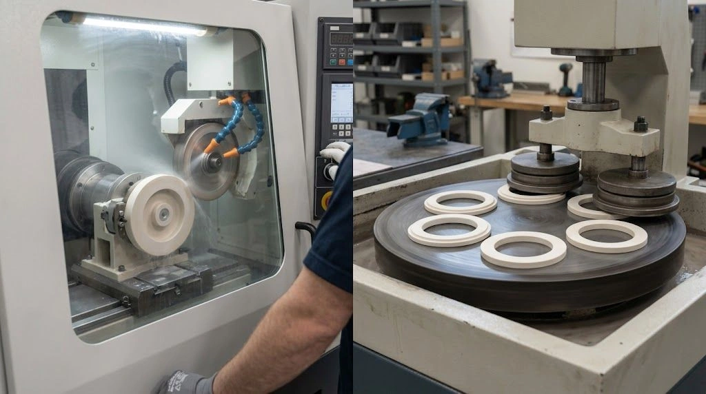
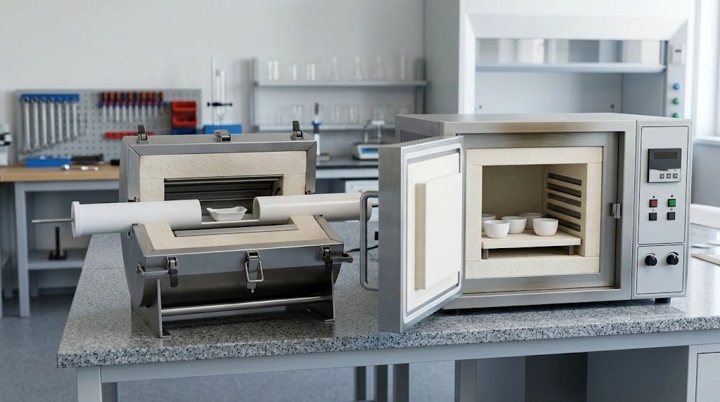
Real ceramic finishing workstations showing bonded-wheel grinding and broad-area lapping as distinct manufacturing operations.
What Actually Changes: Roughness, Flatness, Parallelism, and Stock Removal?
Texture, form, orientation, size, and subsurface integrity are separate characteristics. Lapping may influence several without creating one universal “precision” result.
Texture Is Not Flatness
Ra and other profile parameters describe height variation along a defined trace after specified filtering and evaluation. They do not establish whether the whole ceramic seal face or mounting surface is flat. A very smooth local trace can exist on a bowed or wavy face.
Flatness controls the form of one surface independently of a datum. Parallelism controls the orientation of a surface relative to a datum. Total thickness variation depends on the relationship between opposing surfaces and on how thickness is sampled or mapped. These characteristics must be stated and verified separately.
A ground face can meet all requirements without lapping. A lapped face can still fail parallelism if support, stock, datums, or the opposing face are uncontrolled.
Lay, Contact, and Functional Response
Grinding lay can influence lubrication, sliding, bonding, and leakage. Lapping often produces a more multidirectional pattern. Two surfaces with similar Ra can behave differently because of lay, peaks, valleys, waviness, pull-out, edges, or material-ratio behavior.
The measurement system must fit the function. ISO 21920-2:2021 defines terms and parameters for profile surface texture; ISO lists it as published but under revision as of this article’s preparation. ISO 25178-2:2021 covers areal surface-texture parameters and remains published. The drawing should identify the applicable standard and parameter family rather than relying on an isolated Ra value.
Subsurface Integrity Is Independent
A smooth trace is not proof that machining cracks are absent. NIST research on machining cracks reports that grinding flaws can control the strength of finished ceramics and that crack size and form depend strongly on the machining route. A separate NIST silicon-nitride case study found strong relationships among grinding direction, wheel grit, and observed flaws. These results demonstrate a mechanism and inspection risk; they are not universal strength predictions for every ceramic.
Fine lapping may remove affected material, but lower roughness does not prove deeper cracks are gone. Critical parts may require process qualification, fractography, nondestructive evaluation, or part-specific validation.
Process-Output Comparison
| Attribute | Ground ceramic surface | Lapped ceramic surface | Specification implication |
|---|---|---|---|
| Material removal | Establishes dimensions and removes larger stock | Normally makes smaller corrective removal | Define starting condition and finishing allowance |
| Surface texture | Often has directional wheel lay | Often has lap-motion-dependent, multidirectional texture | Specify parameter, direction, filtering, and evaluation condition |
| Flatness | Can be controlled with suitable machine and setup | Can refine accessible planar form | State flatness separately from roughness |
| Parallelism | Depends on datum setup and opposing-face control | Can refine paired faces in a controlled route | Define datum and parallelism requirement |
| Thickness consistency | Primarily established during dimensional grinding | May refine paired flat components | Define locations or mapping method |
| Edge condition | May produce chips or breakout | May produce edge roll-off or rounding | Specify chamfer, radius, edge break, and chip limits |
| Subsurface integrity | Grinding-induced damage may occur | May remove some prior damage but does not prove absence | Control and validate the complete route |
| Texture direction | Commonly wheel-path dominated | Depends on lap motion and abrasive distribution | Add lay requirements when functionally relevant |
These outcomes are qualitative. Achievable results depend on material grade, geometry, size, thickness, equipment, fixturing, and inspection method.
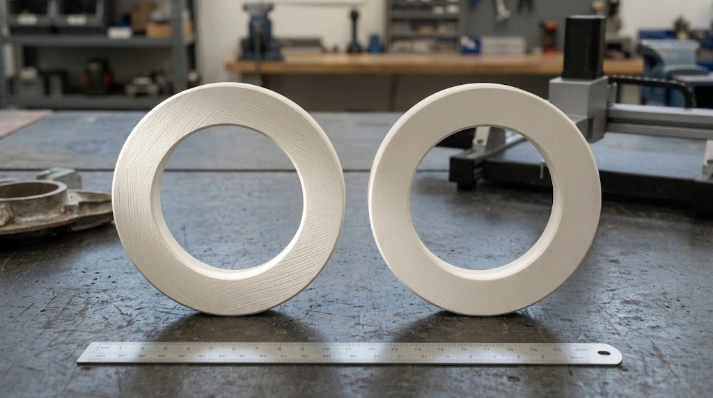
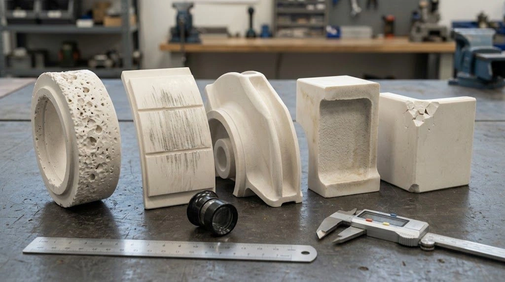
Ground and lapped ceramic seal faces photographed under controlled oblique lighting to reveal differences in lay and surface texture.
When Is a Ground Surface Good Enough—and When Is Lapping Required?
Grinding is sufficient when its verified result meets every requirement—for example, general locating faces, noncritical clearances, compliant-gasket interfaces, and components without exceptional broad-area contact.
Lapping becomes more defensible when the application depends on broad planar contact, controlled leakage, a thin bond line, paired-face sliding, pressure distribution, or a tight relationship between opposing faces. Even then, the requirement should name the functional output rather than merely saying “lap this surface.”
Seven-Step Selection Rule
- Define what the interface does: locate, seal, slide, bond, transfer heat, carry load, or establish a datum.
- Identify whether texture, flatness, parallelism, thickness consistency, lay, edge integrity, cleanliness, or damage depth controls performance.
- Retain grinding when its measured result satisfies all critical requirements.
- Add lapping when accessible planar contact or paired-face geometry cannot be controlled adequately by the chosen grinding route.
- Review another process for bores, curves, interrupted faces, and inaccessible geometry.
- Confirm finishing stock, support, edge protection, cleaning, and contamination controls before release.
- Require inspection results for controlled characteristics instead of accepting a process certificate alone.
Function-Based Process Selection
| Interface or requirement | Ground finish may be sufficient when | Lapping may add value when | Additional review |
|---|---|---|---|
| Locating or mounting face | Measured dimensions and geometry meet assembly needs | Broad contact or tighter datum relationship is required | Check clamping and support |
| Compliant-gasket seal | Gasket accommodates the verified texture and form | Leakage target depends on more uniform face contact | Confirm gasket and pressure conditions |
| Hard ceramic seal pair | Ground texture and form are validated for the pair | Leakage, contact distribution, or running behavior requires refined faces | Review counterface, fluid, speed, and heat |
| Sliding interface | Ground lay supports motion and lubrication | Controlled texture or contact distribution requires refinement | Specify lay and lubricant condition |
| Bonding or metallization face | Verified topography and cleanliness support the process | Thin bond line or uniform contact needs refined geometry | Confirm chemistry and cleaning |
| Thickness-critical plate | Grinding meets thickness and parallelism limits | Paired-face processing is needed to refine variation | Define mapping and datum method |
| Bore or curved surface | Fine grinding meets function | Flat lapping is usually unsuitable | Consider honing or another qualified route |
Do not add lapping simply to obtain a reflective appearance. It adds another controlled removal and cleaning step, changes the stock balance, and can affect edges or expose microstructural features. Purchase it only when a measurable interface requirement justifies it.
How Can Surface Finish Be Mis-Specified or Mis-Inspected?
The most common mistake is using “lapped,” “ground,” “polished,” or “mirror finish” as if it were a measurable acceptance criterion. None of these words alone defines roughness, waviness, flatness, parallelism, lay, edge condition, local defects, subsurface integrity, or the inspection system.
Common Specification Failures
An Ra limit without its applicable standard, filtering, evaluation length, measurement direction, and instrument capability can be interpreted differently by two suppliers. A central trace may also miss edge roll-off, scratches, pull-out, or directional texture elsewhere on the face.
Flatness should not be inferred from an assembly-style total indicator reading that also contains setup or orientation effects. Parallelism requires a datum relationship, while thickness variation requires defined locations or a mapping strategy. A coordinate measuring machine, form instrument, interferometer, profilometer, or qualified optical method may each be appropriate for different characteristics; the instrument name alone still does not define the complete measurement procedure.
Low Ra also cannot serve as evidence of crack-free ceramic or higher strength. Historical NASA material-removal guidance emphasizes controlled machining and reporting and warns against relying on surface roughness alone to infer advanced-ceramic strength. It should be treated as historical engineering guidance, not a current product specification.
Surface-Specification and Inspection Matrix
| Functional concern | Incomplete callout | Required specification | Verification route |
|---|---|---|---|
| Sliding or sealing texture | “Smooth” or “mirror” | Profile or areal parameter, limit, direction, and filtering | Calibrated profilometer or qualified optical method |
| Face form | Ra only | Flatness tolerance over the defined functional area | CMM, form instrument, interferometry, or agreed mapping |
| Opposing-face relationship | “Lap both sides” | Datum, parallelism, and thickness requirements | Datum-based dimensional or form inspection |
| Directional contact | Ra without lay | Texture direction or lay restriction | Oriented traces or areal topography |
| Edge leakage or chipping | No edge definition | Chamfer, radius, edge break, and chip acceptance | Optical or dimensional inspection under defined conditions |
| Structural integrity | Low Ra treated as proof | Controlled route plus qualification or agreed validation evidence | Application-specific validation |
| Supplier comparison | Process name only | Common parameter definitions, standards, and report format | Comparable inspection records |
Confirm the drawing-standard system, current revision, instrument capability, sampling plan, and reporting format before release. This prevents a visually attractive surface from passing while the functional geometry fails—or a functional ground surface from being rejected merely because it is not reflective.
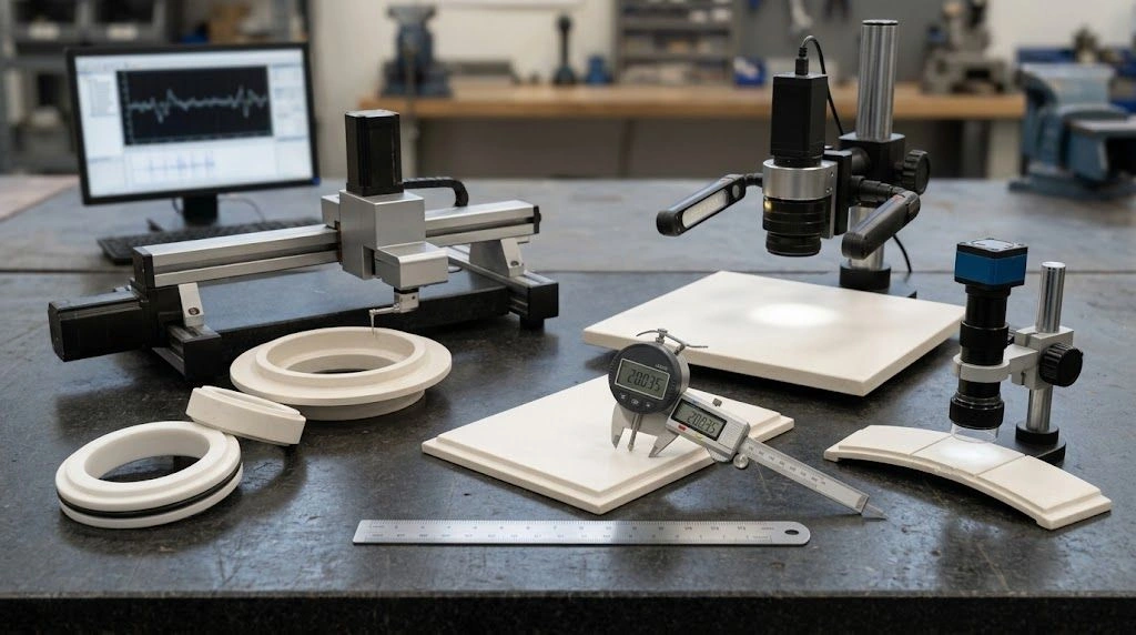
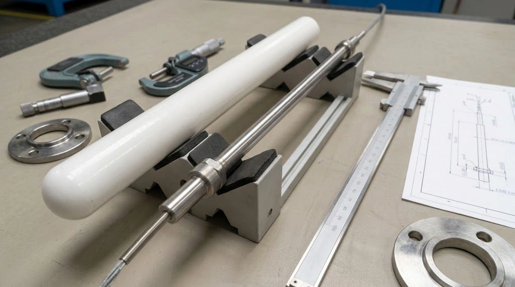
A real metrology setup for evaluating ceramic surface texture, flatness, thickness, and edge condition as separate acceptance characteristics.
What Should a Ceramic Surface-Finish RFQ Specify?
A useful RFQ identifies the material, finished geometry, starting condition, functional faces, mating components, datums, and assembly purpose. Mark each controlled face instead of applying a blanket finish note to the whole part.
For every critical surface, state the selected profile or areal texture parameter, limit, applicable standard, measurement direction, filtering or evaluation condition, and sampling location. Specify flatness, parallelism, thickness, lay, and edge condition separately. Define permitted scratches, pits, pull-out, porosity exposure, chips, and cosmetic marks where they matter.
Explain whether the face seals, slides, bonds, supports a thin interface, transfers heat, carries load, or establishes alignment. Include mating material, pressure, motion, lubricant, medium, temperature, and cleaning restrictions when they affect selection. Ask the supplier to propose the manufacturing sequence and verification method before freezing “ground” or “lapped” as a mandatory route.
When requesting custom ceramic parts, provide the drawing, CAD model, identified functional surfaces, mating-component information, quantities, and required inspection records so the finishing route can be reviewed against the actual function.
Copyable RFQ Checklist
- Drawing revision, CAD model, units, and part orientation.
- Ceramic material, grade preference, or acceptable alternatives.
- Functional and cosmetic surfaces identified separately.
- Finished dimensions and agreed starting-stock assumptions.
- Datum scheme, mating interfaces, and assembly method.
- Profile or areal texture parameter and applicable standard.
- Parameter limit, measurement direction, filtering, evaluation, and sampling conditions.
- Flatness, parallelism, and thickness requirements stated separately.
- Surface lay, contact-pattern, or lubricant-retention requirement.
- Chamfer, radius, edge break, and chip-acceptance limits.
- Permitted pull-out, pores, scratches, stains, or cosmetic marks.
- Cleaning, abrasive-residue, and contamination restrictions.
- Load, pressure, motion, speed, temperature, medium, and lubrication.
- Proposed process route, finishing allowance, and critical-edge protection.
- Inspection method, instrument capability, sampling, and report format.
- Prototype quantity, production quantity, destination, and documentation.
Frequently Asked Questions
Is a lapped ceramic surface always smoother than a ground surface?
No. Results depend on the wheel, lap, abrasive, sequence, ceramic microstructure, and measurement conditions. Compare measured parameters rather than process names.
Does lapping guarantee better flatness?
No. Flatness still depends on lap condition, pressure distribution, part stiffness, support, stock distribution, and control. State and inspect the required tolerance.
Can two ceramic surfaces have the same Ra but perform differently?
Yes. Lay, peaks, valleys, waviness, pull-out, edges, flatness, and subsurface damage may differ even when Ra is similar.
Does lapping remove all grinding-induced damage?
Not necessarily. It may remove some affected material, but deeper cracks can remain. Review the grinding route, damage depth, lapping allowance, material, and validation method together.