A slow thermocouple reading can come from heat transfer to the junction, the installed probe position, or the instrument’s measurement and display settings. A sheath or outer protection tube adds a thermal path, while poor placement may put the junction outside the temperature change of interest. First confirm that the process changed at the sensing location. Then compare the installed assembly and the instrument settings before replacing a probe or reducing its protection-tube wall.
“Response time” is meaningful only when the measured object, temperature event, test environment, and response criterion are defined. A bare probe’s published result is not automatically the response of that probe inside a ceramic tube in a furnace. A diagnosis should identify where the delay appears along the process-to-display path.
What Kind of Slow Thermocouple Reading Are You Seeing?
Record what the display actually does before assigning a cause. The reading may begin changing well after a known process event; it may change promptly but approach its final value slowly; it may remain different from a second sensor throughout the event; or the displayed number may update less often than the underlying data. These are distinct observations.
Log the process-event time, controller output or other independent event marker, probe position, raw temperature samples if available, processed trend, and screen refresh. Note whether the comparison sensor is at the same physical location and sees the same medium. A heater command is not proof that the sample or gas at the thermocouple tip changed at that instant.
Slow-reading symptom matrix
| Observed pattern | Possible cause to investigate | Distinguishing check | Next action |
|---|---|---|---|
| Change begins late | Tip outside the changing zone; logging or display delay | Compare event timing, tip position, raw log, and displayed value | Correct placement or measurement settings |
| Change begins promptly but settles slowly | Heat transfer through sheath, outer tube, or internal gap | Compare assembly geometry and a controlled response test | Review fit, tip, and required protection |
| Protected assembly appears slower than a bare probe | Added protective path and possibly different exposure | Compare at matched location, medium, temperature step, and mounting | Specify the complete assembly result |
| Readings differ throughout the event | Different locations, calibration, or reference-junction issue | Verify location, thermocouple type, compensation, and reference | Resolve measurement validity first |
| Behavior changes after maintenance | Altered depth, support, gap, end position, or settings | Compare before and after installation records | Restore or requalify the installation |
Each row is a route for investigation, not a diagnosis based on appearance alone. For example, a second thermocouple several centimeters away may faithfully report a different temperature history. Calling the first one “slow” would conceal the actual spatial difference.
Define the event and result
For a response test, define the temperature change and output criterion. Record starting and final temperatures, medium, flow, mounting, data rate, and filtering. Without these fields, a reported time cannot fairly rank installed assemblies.
Where Does Thermal Lag Enter the Installed Assembly?
Heat must reach the measuring junction. In a protected furnace installation, the path can run from gas, load, or wall to the outside of an outer tube; across the ceramic wall and internal space; through the metal probe sheath; and finally to the junction. Radiation, convection, conduction through contacts, and heat carried along the probe may all contribute depending on the installation. No single layer always dominates.
An outer set of ceramic thermocouple protection tubes can be specified where the probe needs separation from furnace exposure, provided the material and geometry fit the process. Tube OD and wall influence the physical path; tube ID, end shape, probe clearance, and insertion depth influence how the probe sits inside it. A large gap or a junction positioned far from the closed tip can change the thermal coupling. The tube’s protection duty must be retained in any redesign.
Geometry, medium, and published probe data
Probe diameter, sheath construction, junction position, and exposed length affect the assembly. So do the surrounding medium and its movement. A sensor in moving liquid can respond differently from a similar sensor in still gas; furnace radiation and loading create still another condition. DwyerOmega’s response-time resource ties its comparison data to stated test conditions, including the medium and flow. Treat its values as results for those tests, not guaranteed times for a different protected furnace assembly.
A time constant describes progress toward a new equilibrium after an idealized step. A furnace sample may instead warm gradually. Establish its local temperature history before inferring a probe time constant from a controller trace.
Junction construction within the thermal path
A grounded measuring junction may have a more direct thermal route to its metal sheath than an otherwise comparable insulated junction. The difference can matter, yet it is only one part of a probe’s response and brings separate input-circuit questions. A ceramic outer tube does not change the internal junction connection. Compare complete probes with matched diameter, sheath, installation, and electronics before attributing a timing difference to junction type.
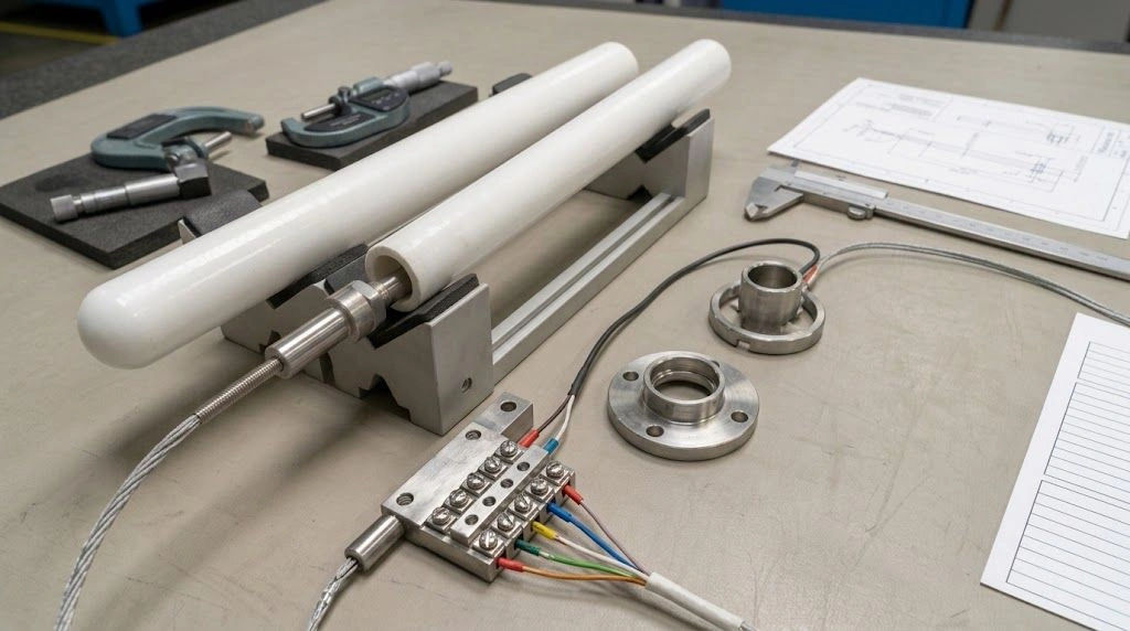
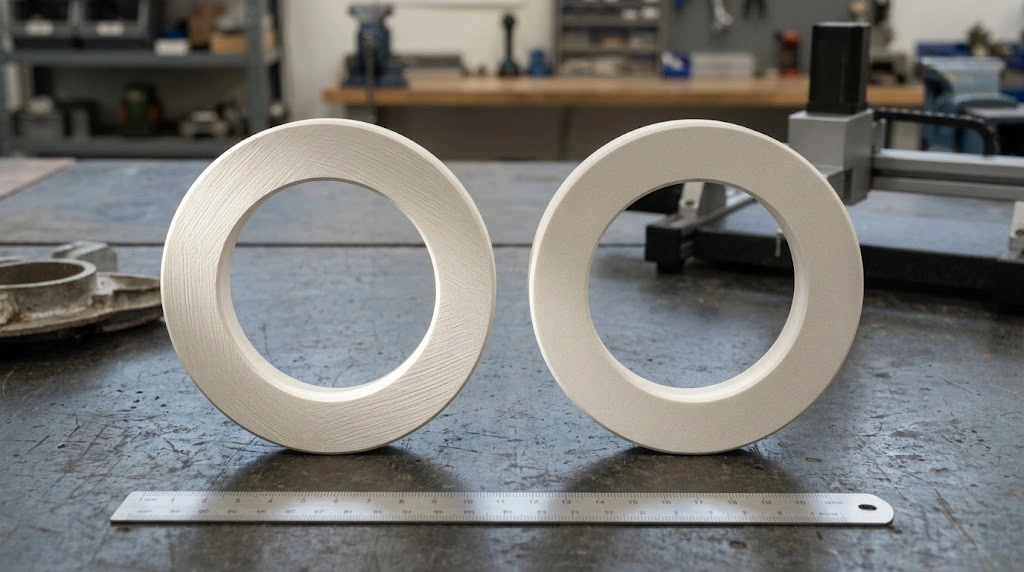
A physical assembly makes the ceramic wall, probe fit, tip position, and mounting path visible.
Is It Thermal Lag, Poor Placement, or Display Filtering?
Start by verifying the supposed temperature event. A furnace heater can switch on before the gas or sample near a sensor changes appreciably. A thermocouple partly outside the useful hot region may report a real, slower local event. Compare the sensor’s position with the location whose transient matters. If a reference sensor is used, place and document it so both instruments observe a comparable exposure.
Next separate raw measurement from displayed trend. An input module can sample at one interval, apply digital filtering or averaging, and update a screen at another interval. The underlying voltage may begin changing before the displayed temperature catches up. Check the controller and data-logger configuration: sample interval, filter time or averaging window, recording rate, and display refresh. Analog Devices’ thermocouple measurement guidance describes why small thermocouple signals often require filtering and reference-junction compensation. Their presence is normal; their particular settings must be considered when timing a transient.
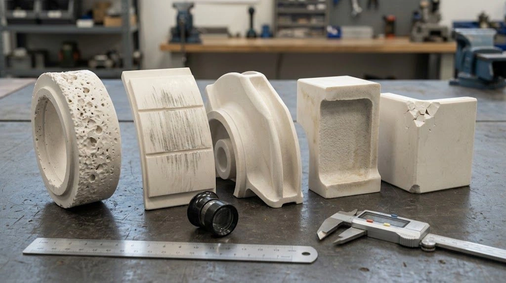
Then inspect the as-installed geometry. Has the probe been withdrawn from the closed end? Was the ceramic tube replaced with a different ID, wall, or tip? Did a maintenance clamp change the supported length or insertion depth? Has the load moved? Compare drawings and installation photos taken before and after service. Check for damage or deposits where these affect heat transfer or measurement integrity.
A practical comparison sequence
- Timestamp the independent process event and the raw acquisition samples.
- Confirm the sensing junction’s physical location and exposure during that event.
- Compare raw data with the controller’s filtered or displayed trend.
- Inspect probe, outer-tube, tip, and mounting dimensions as installed.
- If thermal lag remains plausible, test the existing and proposed assemblies under the same defined conditions.
Do not use two sensors at different positions to declare one product faster without accounting for local temperature histories. A useful comparison holds the test medium, flow or exposure, temperature change, placement, instrumentation, and response criterion constant wherever feasible.
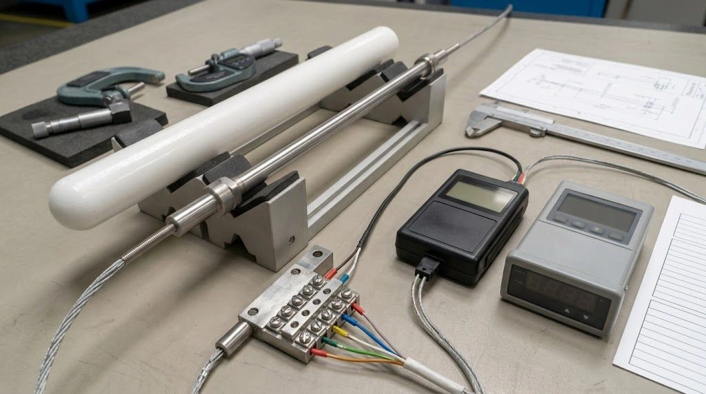
The probe, logger, and controller must be checked as separate stages of the displayed reading.
Which Change Can Improve Response Without Losing Protection?
Make the change that addresses the observed cause. If raw samples track the temperature event while the screen lags, review sampling, filter, and display settings with the instrumentation engineer. If the probe is outside the intended measurement zone, correct placement and support, then repeat the comparison. If a protected assembly shows thermal lag under a controlled test, review its geometry and contact path with the probe and ceramic-part suppliers.
For a needed outer tube, candidates for review can include probe position relative to the closed tip, bore clearance, end geometry, diameter, and wall thickness. A different design may alter response, but it can also alter mechanical strength, thermal-cycle resistance, chemical compatibility, and installation fit. A thin wall or different ceramic should therefore be an engineering proposal with an acceptance test, not a generic speed guarantee.
Preserve the protective function
Corrosive vapors, deposits, abrasion, accidental contact, and handling can justify a separate barrier. Removing it to make a bare probe respond faster may expose the sensor to a different failure mode. Specify what the original tube must prevent and check whether a proposed replacement still fulfills that duty. In cyclic furnace service, review thermal gradients and supports as well as the steady operating temperature.
The same caution applies to a smaller probe. A smaller sheath may reduce thermal mass in some configurations, but it can change durability, measurement location, and compatibility with the existing port or ceramic tube. Verify the complete installed assembly’s response and service requirements together.
What Should a Replacement Assembly RFQ and Response Test Include?
Separate the inputs for the probe supplier, the protection-tube supplier, and the instrumentation owner. All three need the same description of the measurement point and timing problem. Ask for dimensions and test evidence that refer to the proposed assembled installation, rather than combining an isolated probe speed claim with an unrelated ceramic drawing.
Probe and protection-tube RFQ checklist
| Owner | Information to provide or confirm |
|---|---|
| Probe supplier | Thermocouple type, junction structure and position, metal sheath material and OD, tip form, probe length, leads, and connector |
| Ceramic-tube supplier | Required protection, material candidate, open or closed end, OD, ID, wall, closed-tip geometry, total length, straightness, and critical tolerances |
| Installation engineer | Furnace port, support and seal, insertion length, probe-to-tube clearance, tip-to-junction position, hot-zone location, and expansion allowance |
| Instrumentation owner | Input module, sampling interval, filters, averaging, display update, logging, and reference-junction compensation |
| Process owner | Temperature cycle, atmosphere, vapors or deposits, flow or loading, and the transient to be measured |
For a damaged old tube, document an undamaged reference region and the mating interface. Confirm whether the probe tip should contact a designed seat or remain at a specified clearance; do not assume contact is safe or required. Mark the datum from which insertion length and junction location are measured.
Define a response test that can be repeated
Agree on the medium, flow or exposure, starting and final temperatures, how the change is produced, the assembly’s position and support, and the output criterion. Record raw and processed data, acquisition and display settings, and the reference sensor’s location. Compare the existing and proposed arrangements under matched conditions as far as the application permits. If an in-furnace process cannot produce a clean step, report the actual test profile and the measured lag against a documented reference instead of inventing a universal time constant.
Only after diagnosis implicates the outer barrier should a revised protection-tube drawing be sent for review. The RFQ should explain both the required protective duty and the response verification target, without promising a specific improvement before a controlled assembly test.
Frequently asked questions
What does thermocouple response time measure?
It describes how a specified sensor responds to a temperature change under stated conditions. The response criterion, medium, mounting, and geometry must accompany the reported time.
Can a ceramic protection tube make a reading slow?
It can add a heat-transfer path. The installed result also depends on tube and probe geometry, gap, tip position, exposure, and measurement settings.
How can I tell whether the controller is causing the apparent delay?
Compare time-stamped raw samples with the displayed trend and review sampling, filtering, averaging, and screen-update settings during the same event.
What should a replacement specification prioritize?
Define the correct measurement point and protective duty, then specify probe and outer tube separately and test the complete assembly under agreed conditions.
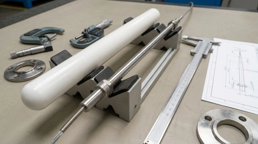
The actual probe, closed-end tube, and mounting hardware establish the dimensions for a response-focused RFQ.