A furnace reaches its setpoint, but the indicated temperature changes from one run to the next. Is the thermocouple aging, is the reference junction warmer, or has the probe moved closer to a cooler wall? These possibilities lead to different repairs. Replacing a protection tube will not correct a bad terminal connection; recalibrating an indicator will not seal a cracked tube.
Use thermocouple drift for a persistent change in the relationship between the sensor's temperature distribution and its thermoelectric output. In maintenance conversations, the phrase often covers any changing display. First classify the change, then test the measurement chain before deciding what to replace. Record conditions and the as-found configuration before removal. A baseline includes the indicated temperature, independent check reading, controller settings, insertion depth, process load, time at temperature, and the point in the heat cycle when the difference appears.
What Kind of Temperature Change Are You Seeing?
Start with repeatable observations. A sensor that changes gradually after many hot cycles suggests a different investigation from one that jumps after someone opens a terminal enclosure. An apparent error during a rapid ramp may disappear at a steady soak. Avoid judging the probe from a single comparison made at different positions or times.
| Observed pattern | Candidate cause to examine | Distinguishing check | Escalation trigger |
|---|---|---|---|
| Slow, repeatable offset after prolonged exposure | Changed thermoelectric properties of the legs; hot-end contamination | Compare against a suitable reference at the same location and stable process condition; review exposure history | Difference persists after the measurement chain and location are checked |
| Step change after service or rewiring | Reversed polarity, wrong extension wire, loose termination, changed channel setup | Trace the pair from junction to input; verify thermocouple type and instrument configuration | Error follows the connection or instrument channel |
| Reading shifts as the control cabinet warms | Cold-junction compensation or terminal thermal gradient | Monitor reference-terminal temperature and compare with an independent input | Offset correlates with enclosure temperature |
| Difference mainly during heat-up or cooldown | Probe thermal lag, changed insertion depth, local process gradient | Compare at a stable soak and repeat with matched probe placement | Difference remains at equilibrium |
| Intermittent spikes or dropout | Open or damaged wire, moisture, connection fault, electrical interference | Inspect continuity and terminations under a safe maintenance procedure; compare channel behavior | Signal is discontinuous or unstable |
| Difference appears after probe relocation | Changed thermal field along the legs or changed measurement point | Restore documented insertion depth and compare at the same location | Error depends on position even when the process is stable |
The matrix is a triage tool, not a diagnosis. Temperature differences across a large furnace can be real. Compare two probes only when their junction positions, protective assemblies, measurement timing, and instrument settings are controlled. Record whether the suspect reading is high or low, but do not assume a fixed drift direction: the sign depends on the thermocouple type, exposure, altered leg regions, and temperature gradient.
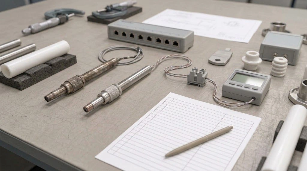
Compare readings under matched conditions and document the as-found installation before changing parts.
How Do Heat and Contamination Change a Thermocouple’s Output?
A thermocouple produces a voltage associated with the temperature gradient along two dissimilar conductors. Standard reference tables relate voltage and temperature for specified thermocouple types; they do not guarantee that a used wire retains its original properties. NIST's ITS-90 thermocouple database is useful for checking the appropriate reference function, while a comparison of the installed assembly must also account for the actual sensor and circuit.
At high temperature, oxidation, changes in alloy structure, and diffusion from nearby materials can alter portions of a thermoelement. Exposure may be strongest near the hot end or wherever the atmosphere enters the assembly. If a changed section of wire lies across a temperature gradient, it can contribute a different voltage from the original wire. The error can therefore change when the probe is inserted to a different depth, even if its hot junction reaches the same nominal temperature. Research on acquired thermoelectric inhomogeneity examines this dependence on changes in the temperature field along the legs. Treat it as a mechanism to investigate, not as a universal drift rate for every furnace.
Contamination is a plausible route when deposits, process vapors, or damaged barriers give reactive species access to the wires. A ceramic barrier can reduce direct exposure when its material, porosity, geometry, and operating conditions suit the process. It cannot repair an already changed thermoelement. If the inspection points to barrier failure, review the sensor and the ceramic thermocouple protection tubes as an assembly: tube material and fit, hot-end closure, mounting, atmosphere, thermal cycling, and the clearance needed for installation all matter.
Thermal cycling may also damage insulation or the junction assembly mechanically. A cracked or open junction can cause an unstable or failed signal; that behavior should not automatically be described as gradual metallurgical drift. Similarly, an intact looking hot tip cannot establish that the wire remains homogeneous. Inspect visible components, then use a controlled electrical and temperature comparison appropriate to the process. A bench check at one temperature may miss an error that appears only when a previously exposed length of wire crosses a different gradient in service.
There is no sound single number for “degrees of drift per year” without specifying wire type and diameter, time and temperature profile, atmosphere, mechanical design, and measurement method. Build a replacement interval from your own comparison records and the consequences of an incorrect reading. Keep removed assemblies and their exposure history labeled when a failure investigation matters.
When Is an Apparent Drift Actually a Measurement-System Error?
The displayed temperature includes more than the hot junction. The instrument measures a small thermocouple voltage and uses a reference-junction temperature to infer the hot-end temperature. At the transition from thermocouple alloy to instrument wiring, the reference terminals should be at nearly the same temperature, and that temperature must be measured accurately. Texas Instruments explains these conditions in its cold-junction compensation application report. A local heater, cabinet airflow, or a poorly located compensation sensor can make the display move while the furnace and thermocouple remain steady.
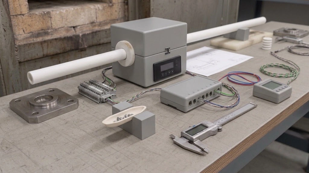
Trace the whole circuit before blaming the exposed probe. Confirm that the instrument is set to the installed thermocouple type, that the positive and negative legs are identified consistently, and that any extension or compensating cable is the specified type with correct polarity. Look for loose screws, corroded contacts, splices, moisture intrusion, and wiring changes since the last accepted comparison. Check channel scaling, offsets, and filtering in the controller or data logger. If a validated reference probe and the suspect probe share a readout, distinguish a sensor difference from an input channel difference by using the plant's approved swap or comparison procedure; preserve safety interlocks and configuration records.
Position matters just as much as electronics. A probe that is pulled back from the process or tilted toward a wall may sample a different region. A deposit on the outside of a tube or a change in tube wall or insertion depth can change heat transfer and transient response. During a ramp, two otherwise sound assemblies may disagree because their junctions heat at different rates. Compare after an appropriate steady soak, then examine the ramp separately if response time is operationally important. Record the reference probe location; “same furnace” does not mean “same temperature.”
An orderly isolation sequence is: verify process conditions and placement; inspect channel setup and wiring; check cold-junction conditions; compare against a suitable reference under controlled conditions; then examine the removed assembly. If the signal follows the instrument channel, investigate the channel. If it follows the probe through an approved swap and persists under matched conditions, inspect the probe and protection system more closely. Do not introduce an offset merely to make one display agree with another until the cause and the effect on control limits are understood.
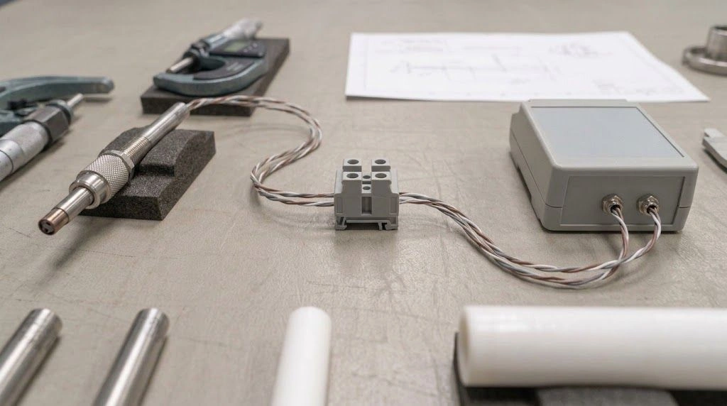
The reference terminals, cable, connections, and instrument setup all influence the indicated value.
Which Inspection Findings Point to the Protection Tube?
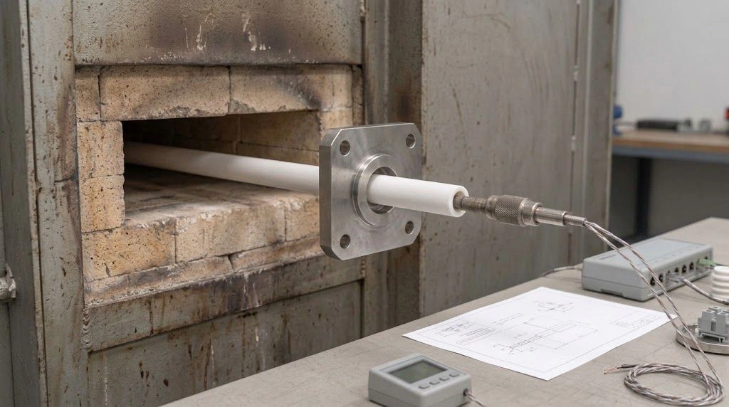
Allow the assembly to cool and follow the site's isolation and handling procedure before removal. Document the installation first: immersion depth, orientation, mounting hardware, distance from walls or burners, and whether the tube was supported or loaded by surrounding equipment. Photograph the hot end, flange or fitting, and any residue before cleaning. A changed orientation or contact point may explain an apparent reading change even if the tube material remains sound.
Inspect the tube for through cracks, chipped ends, erosion, severe glaze or deposit build-up, bending, and damage at the mounting point. Check whether the closed end remains closed and whether the sensor contacts the wall unexpectedly. Where the design allows, inspect the bore and the removed sensor for deposits, discoloration, or damaged insulation. A deposit alone does not identify its chemistry; sample or analyze it if material compatibility is in doubt. A visible crack is a strong reason to assess possible ingress, but a clean external surface is not proof of a sealed or chemically suitable barrier.
Match the finding to its likely effect. A compromised wall can expose internal components to the process atmosphere; a heavy external build-up can alter heat transfer; mechanical interference can change insertion depth or damage the sensor during cycling. Any one of these can coexist with a wiring error. Inspect the old tube and sensor together and retain the pair's identification so that the evidence does not get mixed with other maintenance returns.
Replacement material selection depends on the actual atmosphere and temperature range, including excursions, as well as chemical deposits, cycling rate, impact risk, and mounting design. Do not select a ceramic solely from a nominal maximum temperature. Ask whether the proposed grade and geometry suit the chemical and mechanical environment, and confirm the dimensions against the furnace opening and thermocouple assembly. The purpose of the tube is to create a compatible physical barrier; proof of corrected measurement still requires a controlled comparison after installation.
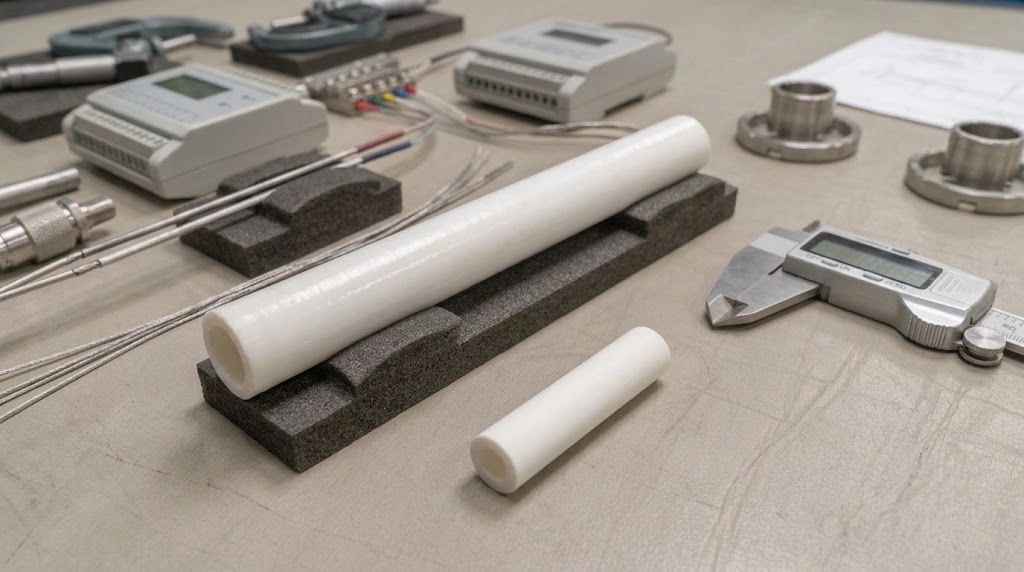
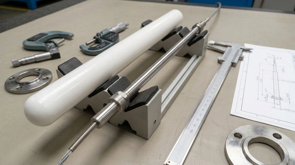
Inspect the closed end, outer surface, mounting area, and fit before specifying a replacement.
What Should a Replacement Review or RFQ Specify?
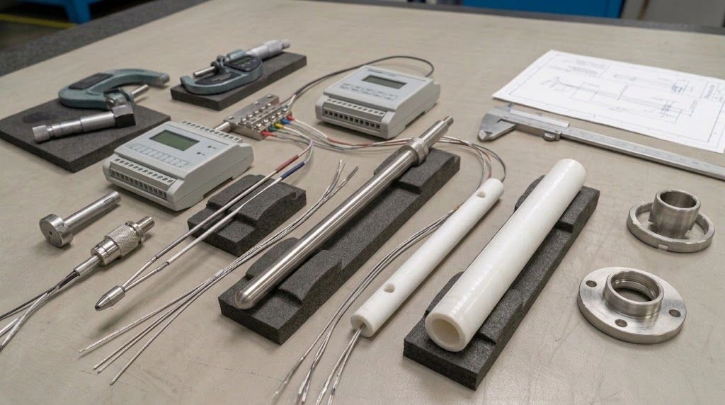
Send a supplier enough detail to distinguish a replacement tube from an apparently similar part. Include the thermocouple type and assembly drawing if available, tube material or current grade, outside and inside diameters, overall and insertion lengths, closed or open end, wall thickness if specified, straightness and dimensional tolerances, and the mounting interface. Identify any concentricity, finish, or fit requirement needed to avoid binding or contact with the sensor. Include photos with a scale and state which dimensions were measured on a used, possibly damaged part.
Describe service rather than providing only a setpoint: normal and peak temperatures, time at temperature, heating and cooling pattern, atmosphere, vapors and deposits, pressure or flow where relevant, horizontal or vertical mounting, vibration, and known contact or abrasion. Include the number of units, required documentation and inspection points, target delivery, and whether a prototype fit check is needed. Ask the supplier to confirm the proposed grade and dimensions in writing and to flag missing compatibility information. If failure analysis is underway, share observations as observations, not as a proven chemical diagnosis.
After installation, record the new insertion depth and instrument configuration. Compare with a suitable reference at a defined operating condition and preserve the as-left reading, date, process condition, and instrument identity. Establish future checks at intervals that reflect process criticality and observed history. If the new assembly still disagrees, resume the measurement-chain investigation; replacing the tube alone cannot establish the cause of every changing temperature display.