Separate leakage performance, breakdown characterization, and withstand acceptance when reviewing ceramic insulators and supplier test reports.
Dielectric strength vs insulation resistance is a comparison between breakdown behavior and leakage performance. Use dielectric-strength evidence to characterize breakdown under defined conditions, insulation resistance to evaluate current at a specified DC voltage and reading time, and a withstand result to verify a specified voltage exposure. A high resistance reading cannot establish all three outcomes. For a ceramic insulating part, the useful requirement identifies the test object, electrical path, environment, and acceptance criterion before any material-property number is treated as evidence of suitability.
What Is the Difference Between Dielectric Strength and Insulation Resistance?
Dielectric strength describes the nominal electric field at breakdown in a defined test; insulation resistance describes how strongly the measured path limits current under specified DC conditions. A dielectric withstand result answers a separate question: whether the test object met acceptance criteria during a prescribed voltage exposure. These results belong in separate report fields. A ceramic material specimen, a finished bushing, and an assembled insulation system may each require different evidence, even when the ceramic grade is identical.
Breakdown Field, Breakdown Voltage, and Resistance
Dielectric strength commonly uses kV/mm. Breakdown voltage uses V or kV and identifies the voltage at which the tested arrangement broke down. ASTM D149-25 addresses breakdown voltage and dielectric strength at commercial power frequencies; its public guidance cautions against direct transfer of material-test results to actual applications.
Insulation resistance uses Ω, MΩ, or GΩ. The basic relationship is R = V / I at the stated DC test voltage and reading time. The current reading needs interpretation because charging and absorption contributions may be present before a sufficiently settled measurement is obtained.
| Metric | Main question | Reporting form | Essential context |
|---|---|---|---|
| Dielectric strength | At what nominal field did breakdown occur? | kV/mm | Specimen thickness, electrodes, waveform, environment |
| Breakdown voltage | At what voltage did the test object break down? | V or kV | Test object, method, observed failure path |
| Dielectric withstand | Did the object meet the specified exposure criteria? | Pass/fail, voltage, duration | Connections, waveform, timing, failure criteria |
| Insulation resistance | How strongly does the measured path limit DC current? | Ω, MΩ, GΩ | Voltage, reading time, environment, measured path |
| Volume resistivity | What bulk conduction property is inferred? | Ω·m or Ω·cm | Specimen dimensions and electrode geometry |
| Surface resistivity | What surface conduction measure is inferred? | Ω, often written Ω/square | Electrode arrangement and surface conditioning |
Units identify different quantities; these entries are not ceramic-grade values or acceptance limits. Surface resistance and surface resistivity remain distinct quantities.
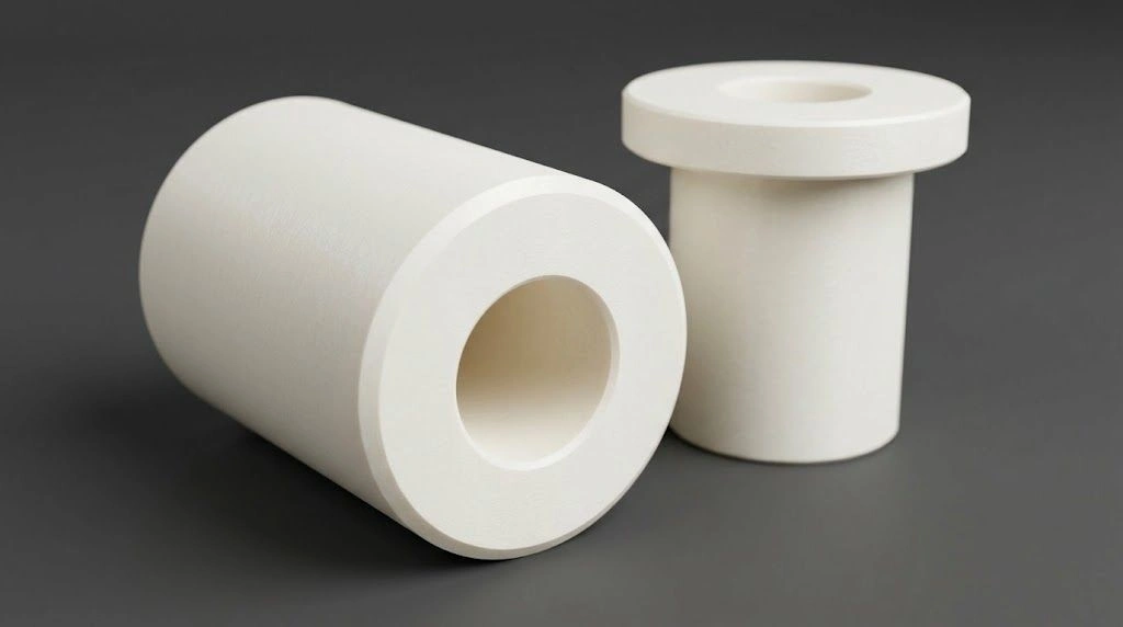
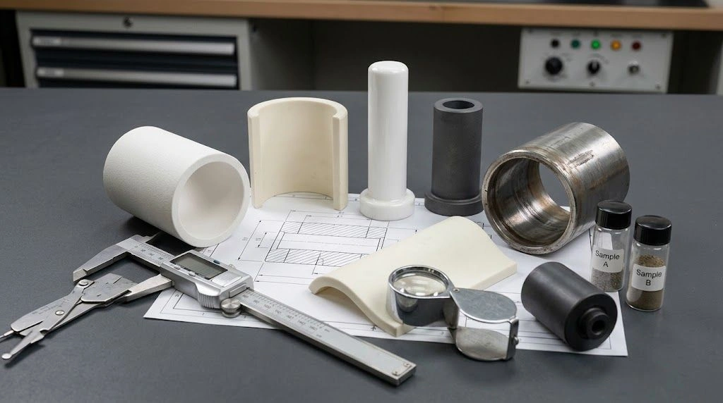
Bores, contact faces, and exposed surfaces define the insulation arrangement; a material property alone does not qualify the finished geometry.
Why Withstand Is a Separate Result
A withstand test, often called a hipot test, checks a defined exposure and acceptance condition. Passing does not reveal the actual breakdown limit or establish service life. Instrument-manufacturer application guidance also distinguishes resistance measurement from withstand testing; application-specific limits cannot be transferred automatically to ceramic parts.
Dielectric constant is another separate quantity. It describes relative permittivity, associated with polarization and capacitance, rather than providing a substitute for resistance or breakdown evidence.
Which Test Conditions Make Insulation Data Comparable?
Comparable insulation data identify the same kind of result and a compatible test basis: voltage form, magnitude, timing, environment, geometry, and electrical path. A resistance value from a guarded material specimen cannot automatically represent an assembled ceramic standoff with exposed surfaces and nearby conductors. Where both low leakage and voltage withstand matter, both requirements need evidence. The document review should establish which requirement each report supports before the reader compares numerical values or negotiates acceptance limits.
Match the Electrical and Environmental Conditions
AC, DC, and pulse conditions should be named explicitly. ASTM D3755-20 addresses breakdown under direct-voltage stress, while ASTM D149 addresses power-frequency testing. Their different purposes do not support a universal AC-to-DC conversion factor for finished ceramic components.
ASTM D257-14(2021)e1 addresses DC resistance and conductance. Its public guidance explains why electrode arrangement and surface conditions affect interpretation. Temperature, humidity, cleaning, and conditioning should accompany the result rather than remain assumptions about the laboratory.
Reading time and exposure duration also serve different purposes. A resistance report identifies when the current was read; a withstand report identifies how long the specified electrical exposure was maintained. Neither can be supplied by the phrase “tested at room temperature.”
Keep Resistance and Resistivity Separate
For an ideal homogeneous slab with uniform bulk conduction and suitable electrodes, R = ρv × t / A relates resistance to volume resistivity, thickness, and electrode area. The model does not describe every bushing, hole, exposed surface, or parallel leakage path. A resistivity value therefore cannot simply be copied into a finished-part resistance requirement.
Similarly, Ebd = Vbd / t can express a nominal breakdown field for an applicable specimen test. Multiplying a datasheet kV/mm value by an arbitrary wall thickness does not establish working voltage or maximum local field in a complex part.
Review the Report in This Order
- Identify the test object: material specimen, finished part, or assembly.
- Separate resistance, resistivity, breakdown, and withstand results.
- Confirm voltage form, magnitude, timing, and environment.
- Identify electrodes, dimensions, and the measured path.
- Map each result to the requirement it supports.
- Request the missing conditions before accepting a comparison.
For custom alumina ceramic parts, connect the electrical requirement to the drawing, conductive interfaces, and intended inspection scope.
Why Can High Insulation Resistance Coexist with a Withstand Failure?
High insulation resistance can coexist with a withstand failure because the tests may apply different electrical stresses or evaluate different paths. A ceramic body may limit DC current under one condition while a surface or surrounding gap becomes limiting during another exposure. A failed test therefore needs a location and event description before it becomes a material rejection. The useful investigation separates through-body, along-surface, and air-gap possibilities, then checks which connections and conditions were actually represented.
Locate the Electrical Path
In a hypothetical scientific-instrument assembly, an alumina insulating spacer separates two conductive mounting features. The review must consider the ceramic between the conductors, its exposed surface, and the surrounding air space. This is an engineering investigation framework, not evidence of a particular customer failure.
- Bulk breakdown passes through the ceramic body.
- Surface flashover follows an insulating surface through the adjoining medium.
- Air-gap discharge crosses a surrounding gap between conductive features.
- Surface leakage can produce excessive current without a through-body breakdown event.
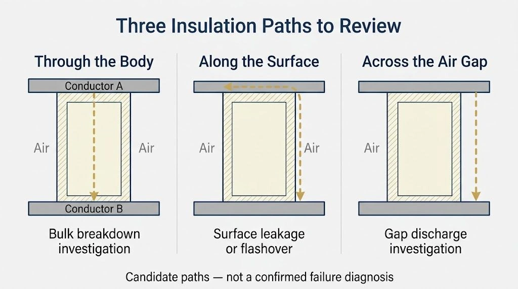
The ceramic body, exposed surface, and surrounding air gap are separate investigation paths, each requiring evidence from the relevant arrangement.
If moisture and contamination provide a more conductive surface route, measured leakage may rise without a puncture through the ceramic. If conductor placement concentrates electrical stress near an edge, a discharge may involve the adjoining surface or gap. These possibilities call for different evidence than a request for higher bulk dielectric strength.
A failed withstand test identifies an unmet test requirement; it does not, by itself, identify bulk ceramic breakdown.
Surface flashover should also remain distinct from tracking. Tracking involves the development of a persistent conductive path associated with surface degradation or deposits; a single observed flashover does not establish that history.
Interpret the Measurement Arrangement
A guard arrangement can exclude selected surface or fixture currents from a measurement. That improves isolation of a chosen contribution, but does not make the excluded path disappear from the real assembly. The report should state what was measured and what was excluded.
AC withstand current can include a capacitive component. Dividing AC test voltage by total AC current does not produce the DC insulation-resistance value required by a separate specification. Likewise, a changing DC reading should not immediately be described as steady leakage.
Improvement after cleaning or drying supports further investigation of surface condition. It does not alone prove that the original material, part, or assembly met every acceptance requirement. Record both the original condition and any conditioning applied before retesting.
Which Insulation Property Should Lead a Ceramic Component Review?
The leading requirement should follow the component’s function: resistance or leakage evidence for a low-current path, breakdown characterization for a material comparison, and withstand evidence for a prescribed voltage exposure. When several functions matter, the qualification plan should retain separate entries. Temperature, surface condition, and geometry remain part of each route. A high material-property number cannot resolve missing information about the conductive interfaces or demonstrate that another test object represents the finished assembly.
| Engineering concern | Lead evidence | Required context | Additional review |
|---|---|---|---|
| Excessive steady DC leakage | Resistance or leakage measurement | Defined voltage, time, temperature, path | Surface, fixture, and bulk contributions |
| Comparing material breakdown | Dielectric-strength test | Controlled specimen and compatible method | Thickness and electrode effects |
| Qualification at a required voltage | Withstand result | Test object, waveform, duration, criteria | Assembly geometry |
| High resistance but failed withstand | Failure-path evidence | Location and event record | Surface, gap, interfaces, or bulk |
| Poor results after humidity exposure | Conditioned measurements | Surface state and exposure history | Contamination and recovery behavior |
| Elevated-temperature insulation | Relevant-temperature electrical evidence | Actual thermal condition and geometry | Grade suitability and surface condition |
This matrix routes engineering evidence; it does not prescribe universal test voltages, resistance limits, or a material ranking.
Choose Evidence That Represents the Function
For an instrument support where leakage affects measurement accuracy, the review starts with the relevant current path and permissible leakage. A material coupon report may assist screening, but it does not define the entire instrument’s error contribution.
For a ceramic feedthrough body, the relevant object may include nearby conductors and interfaces. A material specimen can provide characterization data while leaving the assembled geometry unqualified. The report should make that distinction visible to both engineering and procurement.
Retain Temperature and Surface Boundaries
Dry ambient data do not establish behavior at operating temperature or after humidity exposure. A room-temperature result should remain a room-temperature result until relevant-condition evidence is available. The drawing review also needs the surface state intended for delivery and use, including any metallization or cleaning requirements.
A resistance result and a withstand result answer different acceptance questions and should retain separate conditions in the component specification. Complete documentation supports a review; it is not itself proof that the part has passed qualification.
What Should an Electrical-Insulation RFQ for Ceramic Parts Include?
An electrical-insulation RFQ should identify the part, conductive interfaces, working conditions, and test object before stating separate resistance and withstand requirements. Material characterization, finished-part inspection, and assembly qualification should have distinct scopes. This lets the supplier explain which evidence already exists and which requirements need additional agreement. Numerical limits should come from the equipment requirements and engineering review, with the voltage conditions, timing, environment, and acceptance criteria recorded for each requested result.
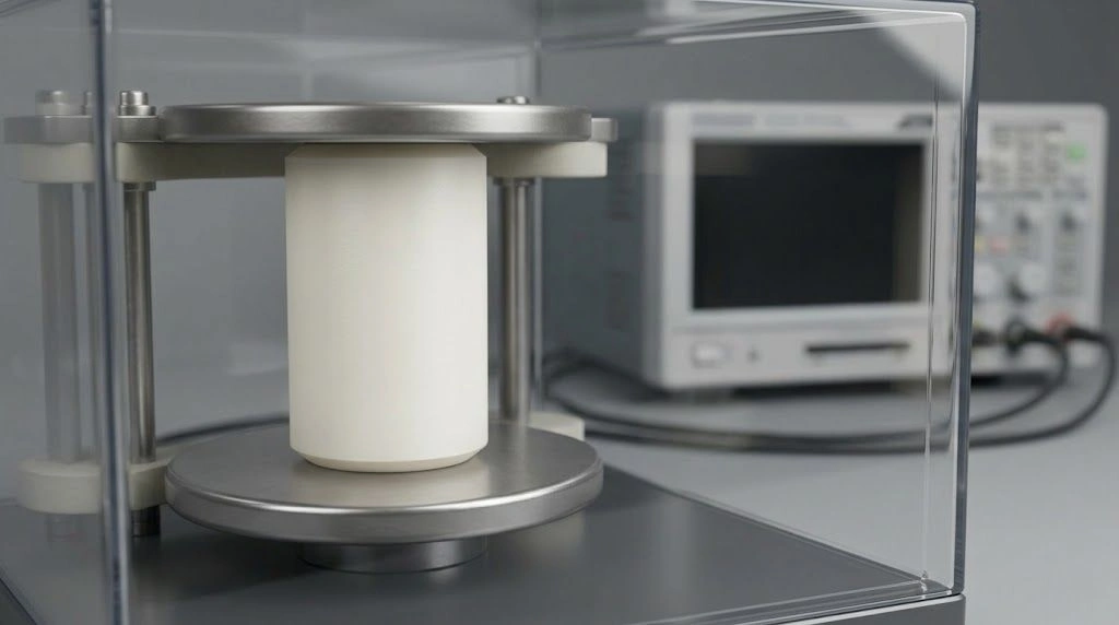
An identified test object and fixture scope help separate material characterization, finished-part inspection, and assembly-level electrical acceptance.
Drawing and Service Information
- Part number, drawing revision, proposed ceramic grade, and quantity.
- Conductive interfaces and intended test connection points.
- Wall thickness, exposed surface path, and surrounding gap geometry.
- Working voltage form: AC, DC, pulse, or mixed service.
- Relevant frequency, transients, and duty cycle.
- Operating temperature, humidity, contamination, and conditioning requirements.
Independent Electrical Requirements
- Insulation-resistance test voltage and reading time.
- Minimum resistance or maximum leakage criterion, with its design basis.
- Withstand waveform, voltage, ramp, duration, and failure criteria.
- Applicable test method and agreed options for each result.
- Material specimen, finished part, or assembly scope for each test.
Inspection, Reporting, and Acceptance
- Sample quantity and qualification-versus-routine inspection scope.
- Critical dimensions, edge and surface condition, and metallization requirements.
- Required reports, conditioning records, and traceability.
- Clear separation of typical material values from contractual acceptance criteria.
The supplier response should identify document coverage, drawing exceptions, and any additional testing that needs agreement. Precision machining and inspection enter this review through the finished geometry and interfaces; neither should imply unconfirmed electrical test capability.
The following statement can accompany the drawing review:
Electrical insulation resistance and dielectric withstand shall be specified and reported separately. Each requirement shall identify the test object, connection points, voltage conditions, timing, environment, and acceptance criteria. Material dielectric-strength data shall not substitute for finished-part or assembly qualification without an agreed engineering basis.
Share the drawing, conductive interfaces, operating conditions, and required electrical checks with ADCERAX at info@adcerax.com for a custom alumina ceramic part review. Include available reports so the review can distinguish existing material evidence from requirements needing further definition.
FAQ
Is dielectric strength the same as insulation resistance?
No. Dielectric strength concerns breakdown under defined electrical stress, while insulation resistance concerns current through an insulation path at a specified DC condition. Their units and test purposes differ. A ceramic review should identify which result supports each requirement instead of treating either property as a complete insulation rating.
Can high insulation resistance guarantee that a ceramic part will pass a withstand test?
No. A high resistance reading describes the measured path under its stated conditions. A withstand test applies a separate exposure and acceptance requirement. Surface paths, surrounding gaps, interfaces, or defects may influence the outcome, so a resistance result alone cannot establish the required withstand performance.
How is insulation resistance different from volume resistivity?
Insulation resistance is a measured resistance for the specified arrangement. Volume resistivity is calculated using resistance and the relevant specimen and electrode dimensions to describe bulk conduction. A volume-resistivity value therefore cannot be copied directly into a finished-part resistance requirement without considering geometry and other current paths.
What should procurement request for a ceramic electrical-insulation review?
Procurement should request the represented grade, test object, connections, voltage conditions, timing, environment, and acceptance basis. The supplier response should separate material characterization from finished-part or assembly results. It should also identify which tests are included in routine inspection and which require additional qualification work.