Thermocouple shunting is an electrical measurement error caused by unintended conductive paths through insulation. At high temperature, insulation resistivity can fall enough for leakage between thermoelements, or through the sheath, to affect the signal. The effective sensing region becomes distributed rather than remaining associated with the intended measuring junction.
In a conventional furnace profile, this often produces a low indication. The direction is not universal: it depends on the leakage network, temperature distribution and measuring circuit. Diagnosis therefore requires more than a low reading or a cold insulation test.
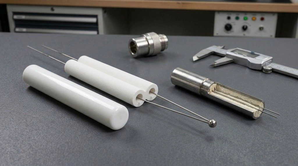
Separate conductors and mineral-insulated probes use different constructions to maintain the intended electrical circuit.
How Does a Thermocouple Normally Produce a Temperature Signal?
A thermocouple uses two dissimilar conductors connected at the measuring junction. Their thermoelectric properties, together with the temperature distribution along the conductors, determine the voltage presented to the instrument. The instrument applies the selected thermocouple relationship and reference-junction compensation to calculate temperature.
The voltage is not produced exclusively at the welded tip. Conductor homogeneity matters wherever temperature gradients exist. Changes in alloy composition can therefore affect the result even when the junction remains intact.
Predictable operation requires electrical separation along the conductors except at the designed connection. A grounded junction deliberately connects the measuring end to the sheath; an ungrounded junction separates it from the sheath. Neither arrangement is inherently a shunting fault.
In mineral-insulated, metal-sheathed construction, compacted mineral insulation surrounds the wires inside a metal sheath. Magnesium oxide is a common insulation material. Separate-wire assemblies may instead use multi-bore ceramic insulators within an outer protection tube.
| Feature | Normal assembly | Assembly affected by shunting |
|---|---|---|
| Conductor connection | Intended measuring junction | Intended junction plus unintended leakage |
| Electrical separation | Leakage negligible for required accuracy | Leakage changes the measured voltage |
| Effective sensing region | Intended junction, subject to other errors | Distributed influence along the heated section |
| Gradient dependence | Normal thermoelectric behavior | Additional interaction with leakage location |
| Cold insulation check | Useful construction check | May still pass despite hot-condition error |
A “virtual junction” is a simplified description of the resulting behavior. It does not necessarily identify one physical point where the original junction has been replaced.
Why Does Thermocouple Shunting Occur at High Temperature?
Insulation has finite electrical resistance. Its resistivity changes with temperature, while the assembly’s resistance also depends on geometry, material condition and the available leakage paths. High room-temperature resistance cannot be assumed to persist throughout a hot probe.
Temperature, moisture and contamination
An NPL/CEM investigation of MgO-insulated Type K and Type N thermocouples found a relationship between falling insulation resistance and increasingly negative indicated-temperature error above approximately 600°C in the tested conditions. The authors also reported construction-dependent behavior and measurement limitations. This is evidence for those sensors and profiles—not a universal onset temperature or rejection threshold. Pearce et al., International Journal of Thermophysics, 2022
Moisture entering hygroscopic insulation can reduce resistance, especially when seals or cable ends are compromised. Heating may remove some moisture, so startup behavior can differ from sustained hot operation. Recovery after heating does not establish that a damaged seal or chemical contamination has been corrected.
Process vapors, carbon, metal deposits, salts and reaction products may also create conductive paths. Cracks or mechanical damage can allow contamination to reach previously protected regions.
How the distributed junction develops
Consider a junction placed in a hot furnace zone:
- The probe stem passes through a temperature gradient behind the tip.
- Insulation in part of the heated assembly becomes more conductive.
- Leakage paths connect regions that should remain electrically separated.
- Those paths alter how the temperature-dependent voltages reach the instrument.
- The output no longer follows the intended junction temperature alone.
Leakage does not need to become a complete metallic short before it matters. Its influence depends on resistance relative to the rest of the circuit, not simply whether a continuity tester sounds.
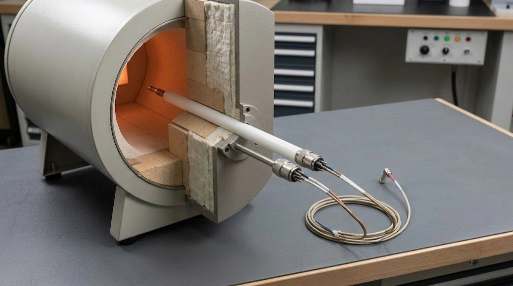
The location of leakage relative to the installed temperature gradient influences shunting error.
Why a low reading is common, but not inevitable
When the tip is hottest and leakage couples it to cooler sections, the effective sensing region can shift toward lower temperatures. A low indication is then plausible.
If the leakage occurs in a hotter section than the intended tip, or involves different sheath and grounding paths, the result can differ. A stable leakage network can also produce a stable bias. Display stability is not proof of accuracy.
| Condition | Possible consequence | What must be checked |
|---|---|---|
| Lower hot insulation resistivity | Increased distributed leakage | Operating temperature profile and construction |
| Moisture ingress | Low resistance or variable startup behavior | End seals, storage and service history |
| Conductive deposits | Local leakage or bridging | Process chemistry and protection integrity |
| Long affected section | More extensive distributed coupling | Heated length and resistance distribution |
| Cooler leakage region | Common tendency toward low indication | Actual tip and stem temperatures |
| Direct conductor contact | An unintended low-resistance junction | Mechanical damage and fault location |
Diameter, conductor spacing, insulation thickness and compaction can all matter. A larger probe is not automatically immune, and changing diameter also changes thermal response and installation requirements.
How Is Shunting Different from Other Thermocouple Errors?
Several faults produce temperature-dependent or position-dependent errors. Shunting should remain a hypothesis until electrical and installation evidence support it.
| Error mechanism | Physical origin | Useful differentiating check |
|---|---|---|
| Electrical shunting | Unintended insulation leakage | Qualified hot-condition evidence plus reference comparison |
| Thermoelectric drift | Changed conductor composition or structure | Exposure history and repeat calibration/comparison |
| Insufficient immersion | Junction influenced by surrounding cooler regions | Controlled insertion comparison |
| Stem conduction | Heat conducted along sheath or tube | Geometry, immersion and heat-transfer assessment |
| Thermal lag | Delayed response to changing temperature | Transient versus settled comparison |
| Direct short | Unintended physical conductor contact | Construction-appropriate continuity and fault analysis |
| Ground loop | Multiple grounds and unwanted electrical paths | Grounding and isolation review |
| Wrong type or polarity | Incorrect wiring or conversion settings | Verify the complete measurement chain |
| Reference-junction error | Incorrect terminal-temperature compensation | Terminal and compensation checks |
| Electrical interference | Coupling from furnace power or nearby equipment | Noise timing, shielding and routing review |
Shunting versus drift
Shunting changes electrical coupling. Drift changes thermoelectric properties. An aged conductor can retain altered properties after cooling, although a nearly isothermal cold bench may not reveal the resulting temperature error.
Both mechanisms can respond to insertion changes because moving the probe relocates affected sections within the gradient. Position sensitivity alone does not distinguish them, and they can coexist.
Electrical error versus heat-transfer error
Stem conduction changes the actual junction temperature relative to the process. Electrical shunting changes the circuit response. A perfectly insulated junction can still read below the intended process temperature because its thermal installation is inadequate.
Radiation, flow and contact conditions also affect what temperature a probe actually reaches. Comparing two probes at the same nominal depth does not guarantee identical junction temperatures if their constructions or surroundings differ.
Grounded junction versus unintended leakage
A deliberate tip-to-sheath connection is part of the design. Additional conduction elsewhere is a different condition. Grounding-related noise or offsets must also be investigated independently; choosing an ungrounded junction does not by itself eliminate every high-temperature error.
How Can Thermocouple Shunting Be Diagnosed and Reduced?
Build the diagnosis from several independent observations. Temperature-dependent error, hot insulation behavior and sensitivity to the installed gradient are more informative together than any one symptom.
1. Verify the measurement chain
Confirm thermocouple type, polarity, extension or compensating cable, connector compatibility, transmitter settings and reference-junction compensation. Review input characteristics, shielding, grounding and terminal condition.
Record raw voltage where appropriate to the approved measurement procedure. This can help separate conversion/configuration problems from changes already present at the sensor output.
2. Compare with a suitable independent reference
Place the reference junction close to the suspect junction and document insertion, atmosphere, stabilization and uncertainty. Consider differences in thermal response and conduction. A controller setpoint is not an independent reference temperature.
Record comparisons over relevant operating conditions rather than relying on one point. Controlled heating and cooling may reveal repeatability, hysteresis or power-related interference, but the test sequence must suit the equipment.
3. Investigate insertion sensitivity
A controlled depth comparison can expose sensitivity to the axial profile. It can also expose inadequate immersion, conduction or conductor inhomogeneity. Preserve the thermal context and interpret the result alongside other checks.
Do not shorten insertion simply to reduce heated cable length: doing so may replace an electrical problem with a larger immersion error.
4. Use a construction-appropriate insulation test
The two thermoelements in a finished thermocouple are intentionally joined at the measuring end. An ordinary resistance reading between them therefore includes that metallic loop; it is not a direct measurement of insulation resistance.
For an ungrounded assembly, conductor-to-sheath testing may be appropriate under the specified procedure. A grounded tip intentionally provides that connection, so the same interpretation does not apply. Interconductor insulation testing of unjoined cable is a different configuration.
ASTM E780 addresses room-temperature insulation testing and distinguishes applicable cable and junction arrangements. It does not establish hot-condition performance from a cold result. ASTM E780
Do not apply an arbitrary megohmmeter or bias voltage to an installed hot sensor, transmitter or control circuit. Use an approved manufacturer or laboratory procedure, appropriate isolation and suitable equipment. Record the tested paths, voltage, temperature distribution and connection arrangement—not just a resistance number.
5. Inspect and correct the relevant cause
Check cracked tubes, open seals, contaminated terminals, sheath damage and severely bent or pinched cable. Match corrective action to the identified route.
| Risk | Possible response | Limitation or tradeoff |
|---|---|---|
| Inadequate hot insulation performance | Qualify a different sensor construction | Requires assembly-level evidence |
| Moisture entry | Improve sealing and storage | Does not remove existing chemical damage |
| Process contamination | Review compatible protection and seals | Added protection can slow response |
| Poor conductor spacing | Review multi-bore insulation geometry | Material and hot environment still matter |
| Diameter change | Evaluate electrical and mechanical benefits | Response, conduction and mounting also change |
| Electrical interference | Improve isolation, shielding and routing | Does not repair internal leakage |
| Damaged probe | Replace and investigate the cause | Repeated exposure may reproduce failure |
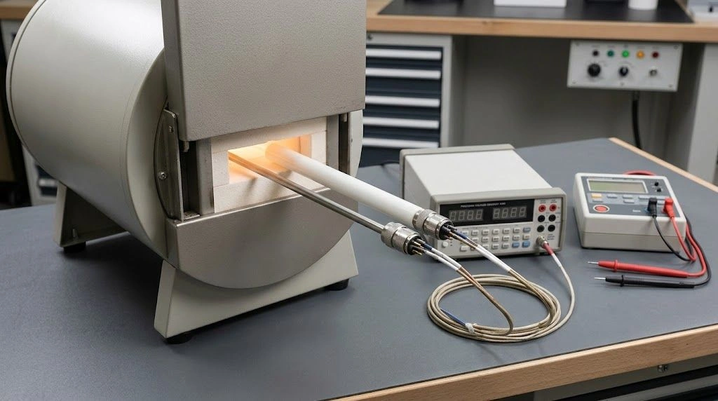
A reference comparison supports diagnosis when junction position, thermal conditions and measurement uncertainty are documented.
Copyable troubleshooting record
| Sensor ID/type | Construction/diameter | Junction style | Protection | Insertion | Setpoint | Reference | Indicated | Difference | Insulation test configuration | Resistance | Observation |
|---|---|---|---|---|---|---|---|---|---|---|---|
Attach the axial profile, stabilization time, uncertainty, test voltage and instrument details. Define the difference consistently, for example indicated temperature minus reference temperature.
Expert Insight: The Installed Gradient Belongs in the Specification
A calibration establishes behavior under its stated conditions. It does not automatically reproduce the temperature distribution encountered when a long probe crosses a furnace wall, a cooled flange and a hot chamber.
Consider two installations with the same intended tip temperature but different heated lengths. Their leakage distributions and thermal conduction paths can differ. A replacement that matches only the tip-temperature rating may therefore behave differently in service.
Keep electrical and thermal questions separate during review. Ask where conductive paths can develop, and separately ask whether the intended junction reaches the process temperature. Then examine how the proposed insulator, protection tube and mounting alter both.
Acceptance criteria should name the assembly, exposure and test arrangement. A nominal ceramic purity, a single cold resistance value or an unchanged display cannot substitute for that evidence.
What Should Be Specified for Ceramic Thermocouple Insulators and Protection Tubes?
A multi-bore insulator separates and supports conductors. An outer protection tube limits environmental exposure and provides containment. These functions are related but distinct.
| Component | Main role | Performance boundary |
|---|---|---|
| Multi-bore ceramic insulator | Maintain conductor spacing and electrical separation | Cannot independently guarantee sensor accuracy |
| Outer protection tube | Limit process exposure | Cannot restore defective internal MI insulation |
| Metal sheath | Contain mineral insulation and conductors | Can participate in unintended leakage paths |
| Terminal insulator | Separate connections at the cold end | Does not establish hot-zone performance |
| End seal | Limit moisture or gas ingress | Requires compatible materials and service conditions |
For alumina, review grade, relevant hot resistivity data, porosity, additives, contamination and atmosphere compatibility. Resistivity is a material characteristic under specified conditions; insulation resistance also depends on the finished geometry and surface condition. Purity percentage alone is insufficient.
Specify bore count, diameter, center spacing, minimum web, OD, length and conductor clearance. For protection tubes, include ID, wall, closed-tip geometry, insertion, supports, orientation and sealing zone.
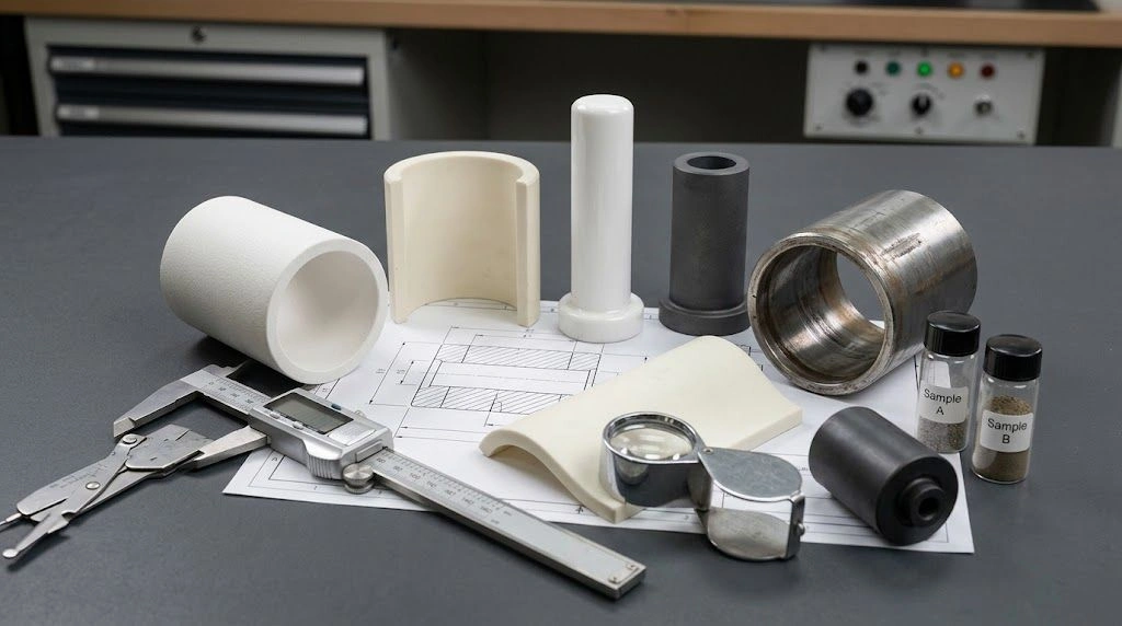
The complete thermocouple manufacturer or integrator must validate insulation behavior, calibration and installed accuracy. When component review is needed, specify custom ceramic tubes and insulators by conductor layout, temperature profile, atmosphere, insertion depth and drawing.
Copyable RFQ
Subject: RFQ — Ceramic Thermocouple Insulator / Protection Tube
Component required:
Thermocouple type and conductor materials:
Conductor diameter:
Grounded / ungrounded / exposed junction:
MI cable or separate insulated conductors:
Sheath material and instrument input:
Ceramic insulator:
- Preferred material/grade:
- Bore count and diameter:
- Bore center spacing and minimum web:
- OD and length:
- Continuous or segmented:
- Conductor clearance:
- Straightness and end-face requirements:
Protection tube:
- OD / ID / wall:
- Total length and insertion depth:
- Open end or closed-tip geometry:
- Orientation, supports and unsupported length:
- Mounting and sealing details:
Service:
- Working and maximum/upset temperature:
- Heated length and axial temperature profile:
- Hold time and heating/cooling rates:
- Atmosphere, chemicals, vapors and deposits:
- Pressure, flow and thermal cycles:
Electrical and system requirements:
- Insulation-resistance criterion:
- Tested electrical paths:
- Test temperature, voltage and method:
- Required response time:
- Required measurement uncertainty:
- Assembly validation responsibility:
Order:
- Drawing and installation sketch:
- Material/inspection documentation:
- Prototype and production quantities:
Frequently Asked Questions
Is shunting a complete short circuit?
Not necessarily. Distributed finite-resistance leakage can affect the signal before direct low-resistance contact develops.
Does shunting always make readings low?
No. Low readings are common in conventional hot-tip furnace profiles, but the leakage location and circuit determine the sign.
Can a sensor pass a cold test and still shunt?
Yes. The operating temperature can substantially change insulation behavior. Cold testing remains useful but has a different scope.
Will an alumina protection tube solve internal MI leakage?
No. It may reduce further environmental attack, but it does not repair the cable’s internal insulation.
Is there a universal temperature or resistance limit?
No. Acceptance depends on construction, temperature profile, test arrangement and required measurement performance.
Conclusion
Thermocouple shunting is a distributed electrical-leakage problem influenced by the installed temperature gradient. It must be separated from drift, grounding, insufficient immersion and thermal conduction before selecting a remedy.
Provide ADCERAX with conductor layout, ceramic dimensions, atmosphere, axial profile and electrical-test requirements for component review. Validate the completed sensor and installation separately; a ceramic component is one part of the measurement system.