A ceramic part is feasible only when its critical features can be manufactured with process margin, measured by an agreed method, and repeated under a defined acceptance plan. A one-off sample may be machinable yet not production-feasible if its datum cannot be established, a probe cannot reach the feature, measurement uncertainty consumes too much of the tolerance window, or a destructive test lacks a sampling rule. Before freezing the drawing, connect every critical-to-quality characteristic to its manufacturing stage, datum, inspection method, conformity rule, and production evidence.
What Are the Three Gates of Ceramic-Part Feasibility?
“We can make it” is incomplete. A ceramic drawing must pass three related but separate gates:
- Manufacturing: Can the selected ceramic, forming route, firing cycle, machining sequence, fixture, and tool path produce the feature with useful margin?
- Measurement: Can the stated characteristic be accessed and evaluated from stable functional datums with suitable task-specific uncertainty?
- Production: Can the result be repeated across parts, setups, tools, and firing lots under one agreed acceptance rule?
A grinder may produce one deep bore within size while its axis remains impractical to verify. A technician may adjust a prototype until it passes although the route lacks production margin. An accessible dimension may still be unstable through sintering. Each case requires a different response.
| Gate | Primary question | Typical warning | Required response |
|---|---|---|---|
| Manufacturing | Can the feature be produced with margin? | Distortion, chipping, inaccessible grinding path, inadequate finishing stock | Change geometry, process stage, fixture, or tolerance |
| Measurement | Can the requirement be verified unambiguously? | Unstable datum, blocked probe path, method disagreement, excessive uncertainty | Define the measurand, setup, access, method, and decision rule |
| Production | Can conforming output be repeated? | One acceptable sample, drifting lots, repeated adjustment, heavy sorting | Qualify a pilot lot and establish production controls |
Review these gates together. A finishable surface needs support and clamping that do not damage or distort the workpiece. The CeramTec technical ceramics manual recommends including them in the design concept when a surface requires finishing. The same principle applies to inspection fixtures.
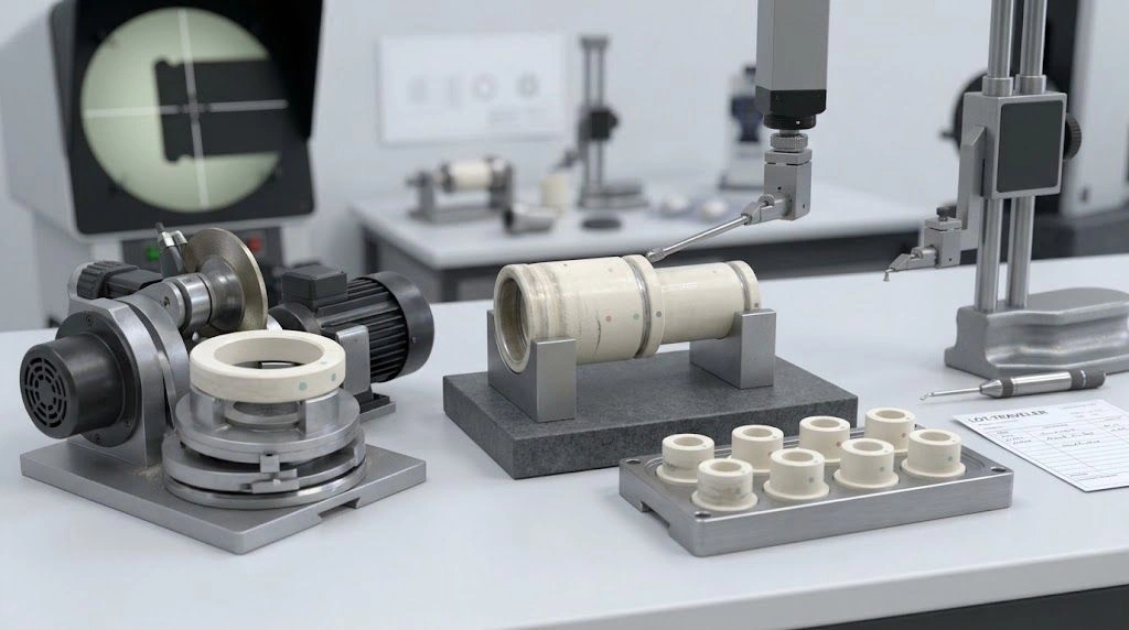
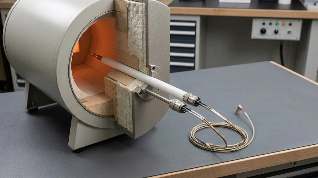
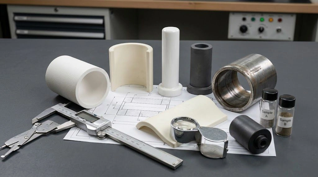
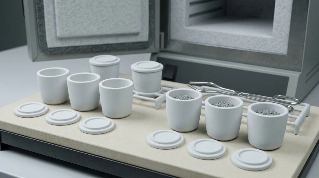
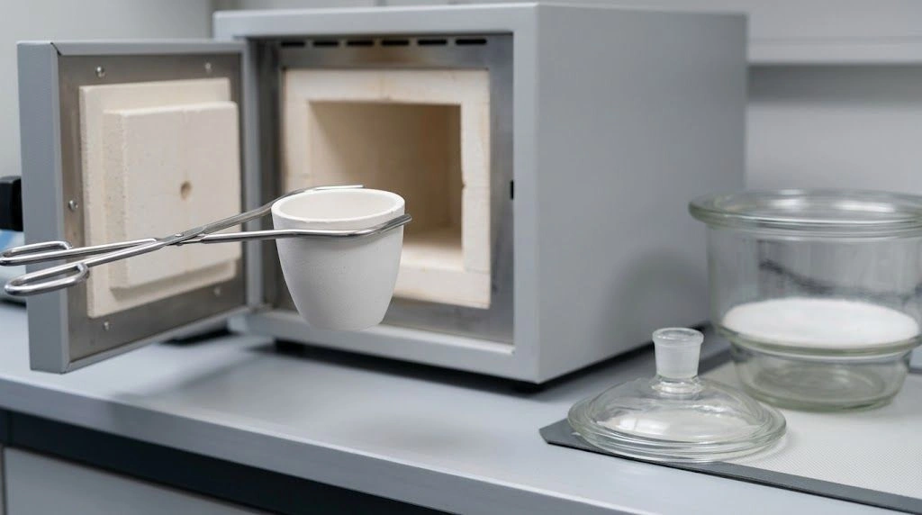
Three physical setups separate making one feature, verifying it from a stable datum, and demonstrating repeatable production.
How Do Different Tolerances Change the Manufacturing Route?
Tight callouts are not interchangeable. Size, form, orientation, location, runout, surface texture, and visual criteria control different aspects of the part. Tightening an outside diameter may require cylindrical grinding. Controlling its runout to an internal bore may require both features to be finished or inspected from a common axis. Flatness controls one surface; parallelism controls a relationship. Roughness does not establish flatness, waviness, or sealing geometry.
ISO 1101:2017 defines geometrical-specification language and interpretation, while ISO 5459:2024 covers datums and datum systems. The supplier must know what is controlled and how its reference is established—not merely see a small number.
| Requirement | Likely route implication | Inspection implication | Feasibility can fail when |
|---|---|---|---|
| OD or thickness | As-fired control or finish grinding | Micrometer, comparator, or CMM according to definition | Limited stock or a fragile wall prevents correction |
| Deep bore | Internal grinding, honing, lapping, or redesign | Bore gauge, air gauge, CMM, replica, or CT | Tool or sensor cannot reach the required depth |
| Flatness | Controlled support and selective face finishing | Form instrument, CMM, interferometry, or defined plate method | Support changes the measured shape |
| Parallelism | Coordinated finishing from a stable datum | Datum-based measurement | The datum is rough, curved, small, or unstable |
| Runout | Common-axis machining and controlled setups | Rotary gauge or validated CMM strategy | Related features cannot share a reliable reference |
| Surface texture | Grinding, lapping, or polishing | Contact or optical system with defined evaluation settings | Access, direction, filter, or evaluation length is missing |
| Edge condition | Chamfer, radius, deburring, and protected handling | Optical or controlled visual inspection | “Break edge” or “no chips” has no measurable limit |
| Internal profile | Specialized tooling or geometric redesign | CMM, optical, replica, or CT | Neither production nor inspection access is validated |
Finishing is not merely a dimensional step. ASTM C1495-16(2023) specifically addresses the effect of surface grinding on advanced-ceramic flexural strength. The drawing should therefore identify strength-sensitive surfaces and the required condition, rather than assuming that more grinding is automatically safer.
Start with function. Mark the sealing, locating, bearing, electrical-clearance, and flow-control features, and apply close control where variation affects them. Assign each characteristic to forming, green machining, firing control, or post-fire finishing. Flag inadequate correction stock, unsupported thin walls, inaccessible wheel paths, and relationships that cannot share a setup.
Why Is the Inspection Method Part of Feasibility?
Owning a CMM does not make every drawing inspectable. Define the measurand, datum simulation, support, sensor access, evaluation method, environment, and uncertainty treatment. A deep bore may exclude a stylus; a thin ring may deflect; an as-fired surface may make an unstable datum. Optical access still requires validation for the actual characteristic.
The ISO 10360 family distinguishes CMM configurations: ISO 10360-2 addresses CMMs used for linear dimensions, while ISO 10360-7 addresses imaging systems. Probe geometry, point density, filtering, alignment, fixturing, and software can still change the result.
Measurement uncertainty changes conformity decisions near a limit. ISO 14253-1:2017 establishes decision rules that account for uncertainty when verifying conformity or nonconformity. NIST guidance on metrological traceability likewise explains that traceability alone does not guarantee fitness for purpose; the associated uncertainty must suit the measurement need. Instrument resolution, calibration, and task-specific uncertainty are not synonyms.
For each CTQ, the drawing or quality plan should answer:
- What physical or derived quantity is being evaluated?
- Which surfaces establish the datum system, and how are they simulated?
- Is the part measured free, supported, clamped, or assembled?
- Can the tool and sensor reach the full evaluation zone?
- Which contact force, scan strategy, filter, cutoff, direction, or algorithm applies?
- What uncertainty and conformity rule govern results near the limits?
- What report is required: value only, setup description, raw data, image, or traceability evidence?
Surface texture needs particular care. ISO 21920-2:2021 defines profile terms and parameters; “polished” does not identify a parameter, evaluation length, direction, or zone. Visual requirements need defect type, size, location, lighting, magnification, and reference examples. Without these, customer and supplier can reach different decisions on the same part.
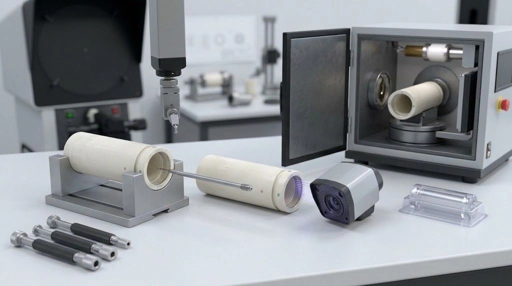
A deep internal feature may be manufacturable yet remain unresolved until sensor access, datum simulation, and method uncertainty are validated.
Does a Conforming Prototype Prove Production Feasibility?
No. A prototype shows that at least one result was achieved under its particular conditions. It does not establish the process distribution, firing-lot variation, tool-wear trend, setup reproducibility, measurement reproducibility, yield, or risk of drifting toward a specification limit.
Qualification should therefore progress in stages:
- Engineering sample: Demonstrate that the material, route, geometry, and measurement concept are plausible.
- First article: Verify that the released drawing, manufacturing revision, datum setup, and inspection report agree.
- Pilot lot: Observe variation across representative parts, setups, tooling condition, and firing or material lots.
- Production control: Define CTQ monitoring, sampling, calibration, nonconformance handling, traceability, and change approval.
| Status | Available evidence | Commercial decision |
|---|---|---|
| Green | Process margin, accessible measurement, agreed uncertainty and decision rule, representative repeat-lot evidence | Release for production quotation |
| Amber | One or more samples appear feasible, but fixture, measurement, or variation evidence remains open | Quote a prototype or pilot phase with stated risks |
| Red | A requirement cannot be produced, accessed, measured, or interpreted consistently | Revise the specification before quotation |
Amber status should preserve the unresolved assumptions in the quotation, including the affected feature, proposed verification step, sample quantity, responsible party, and evidence needed before production approval or release.
One hundred percent inspection may sort nonconforming parts, but it cannot make an unstable process capable. Destructive strength, density, thermal-shock, or material tests need a lot definition, specimens, sample quantity, method, and acceptance rule. ISO 2859-1:2026 provides AQL-indexed schemes for inspection by attributes, but each project must select its plan and risk basis.
Production approval should not rest on a first-article report alone. Ask what was reworked, selected, repeated, or excluded. Record open characteristics as qualification risks. Base capability claims on representative data from the intended route, not another material, geometry, instrument, or supplier.
What Belongs in an Inspection-Aware Ceramic RFQ?
Freeze the drawing only after manufacturing and inspection interpretations agree. Mark each CTQ and its functional reason. Identify datums, finished and as-fired surfaces, measurement condition, and method-sensitive characteristics. Define surface-texture evaluation, edge-defect criteria, reporting, lot boundaries, and destructive-test sampling.
Use this handoff sequence:
- Provide material grade, drawing revision, 3D model if available, annual and lot quantities, and service conditions.
- Separate CTQs from reference and noncritical dimensions.
- Define the functional datum structure and each characteristic’s finished condition.
- Review machining and inspection access for bores, slots, pockets, thin walls, and internal profiles.
- Agree the instrument, setup, evaluation settings, uncertainty, and conformity rule for disputed or high-risk CTQs.
- Separate engineering sample, first article, pilot lot, and production acceptance requirements.
- Define reports, raw-data needs, traceability, sampling, nonconformance response, and change control.
- Require the supplier to list exceptions and proposed alternatives before quotation release.
Map each CTQ to its manufacturing stage, capability status, inspection method, datum setup, access limitation, and evidence. Replace “can be made” with: production-feasible, prototype-feasible pending qualification, or specification revision required.
Use the ceramic tolerance and shrinkage design guide to assign features to forming, firing, green machining, or post-fire finishing. Review the ceramic inspection and testing process when defining dimensional, surface, and material evidence. Then submit the controlled drawing through the custom ceramic parts RFQ page for a joint manufacturing-and-inspection feasibility review.
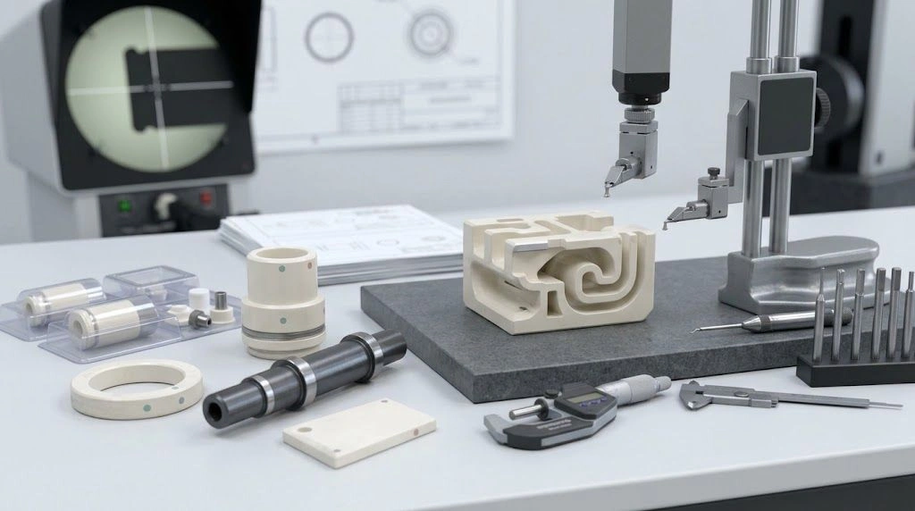
The RFQ bench connects each CTQ to a process stage, datum setup, inspection method, and qualification level before production release.
Frequently Asked Questions
What makes a ceramic-part tolerance feasible?
A tolerance is feasible when the feature can be produced with process margin, measured from a stable functional reference with suitable uncertainty, and repeated across representative production. Material, geometry, size, quantity, machining access, datum structure, and inspection method all affect the answer; no universal tolerance table can approve a specific part.
Can every tight ceramic tolerance be achieved by grinding?
No. Grinding requires wheel access, adequate finishing stock, stable fixturing, and geometry that can tolerate machining forces and edge risk. A deep bore, thin wall, interrupted surface, or linked datum relationship may require a different setup, route, tolerance, or redesign even if the nominal dimension appears grindable.
How should datums be selected for ceramic parts?
Select datums from surfaces that locate or orient the part in its functional assembly and can be simulated repeatably during inspection. Avoid relying on tiny, rough, curved, chipped, or unstable as-fired areas unless the drawing and inspection plan define a workable method for establishing the intended reference.
Can a CMM inspect a deep ceramic bore?
Sometimes, but machine ownership alone proves nothing. Confirm stylus reach, clearance, probing direction, datum access, expected surface interaction, scanning strategy, and task-specific uncertainty. If contact access is inadequate, evaluate a qualified air-gauge, replica, optical, or CT method and define how its results correlate with the requirement.
Does 100% inspection prove process capability?
No. Full inspection may detect or sort certain nonconforming parts, but it does not demonstrate a stable process distribution or adequate margin. It also cannot economically replace destructive tests. Production approval needs representative pilot evidence, an agreed measurement system, defined sampling, and controls for tools, lots, nonconformance, and change.
What inspection requirements should a ceramic RFQ include?
Identify CTQs, functional datums, finished condition, measurement state, candidate method, evaluation settings, uncertainty expectations, and the conformity rule. Add edge and visual criteria, first-article reporting, lot definition, production sampling, destructive-test quantities, traceability, raw-data requirements, and supplier exceptions so quotations share the same acceptance boundary.