PBN tubes are used in MBE effusion cells when tubular source-facing hardware must combine high purity, low outgassing, thermal stability, chemical inertness, and corrosion resistance under ultra-high vacuum. Unlike PBN crucibles — which primarily contain the source charge and control evaporation geometry — PBN tubes may act as delivery tubes, injector tubes, cracker tubes, liners, insulating supports, or vapor-path components in the source assembly. The correct specification depends on source material, operating temperature, condensation risk, tube geometry, wall thickness, RGA limits, cleaning method, and whether the tube directly contacts evaporant or only supports the heater and source assembly structure.
That role-first framing — PBN tube function before dimensions — is the engineering basis for this guide.
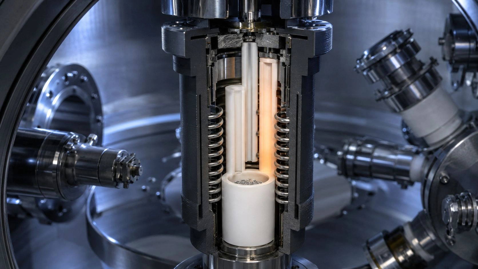
PBN tubes in MBE effusion cells control vapor delivery, injection, and cracking in source-facing positions where high purity, low outgassing, and corrosion resistance are required — tube geometry and thermal design determine whether the source remains clean, stable, and clog-free.
The PBN crucibles and source components at ADCERAX — covering CVD-grown PBN with custom volumes, bores, tubes, wall profiles, and source-specific geometries for MBE and PVD evaporation — are the starting point for the selection decisions described in this guide.
Where PBN tubes fit inside MBE effusion cells
MBE engineers commonly associate PBN with crucibles — and for good reason, since the crucible holds the source material and defines the primary evaporation geometry. But MBE effusion cell assemblies contain multiple hardware elements beyond the crucible, and several of these are tubular in form and source-facing in exposure.
The PBN Tube Roles in MBE Effusion Cells table and the PBN Tube vs PBN Crucible comparison table map the functional distinction:
Table 1 — PBN Tube Roles in MBE Effusion Cells:
| PBN tube role | Function | Main advantage | Main risk | What to verify |
|---|---|---|---|---|
| Injector tube | Guides vapor/radicals toward source outlet | Corrosion resistance and clean vapor path | Condensation, clogging, misalignment | Bore, mouth temperature, source chemistry |
| Delivery tube | Transfers evaporated/sublimated material | Defined vapor path and clean surface | Deposit buildup or source memory | Temperature gradient and conductance |
| Cracker tube | Supports dissociation/cracking zone | PBN stability in reactive source-facing regions | Overheating, deposits, corrosion | Cracker temperature and exposed species |
| Liner tube | Separates source vapor from holder/hardware | Low contamination barrier | Fit stress and trapped residue | Clearance, expansion, cleaning |
| Insulating tube | Supports heater or filament electrically | Electrical insulation and thermal stability | Mechanical fragility | Contact stress and heater geometry |
| PBN ring/tube support | Stabilizes source assembly | Low outgassing support | Cracking under clamp stress | Mounting pressure and thermal cycle |
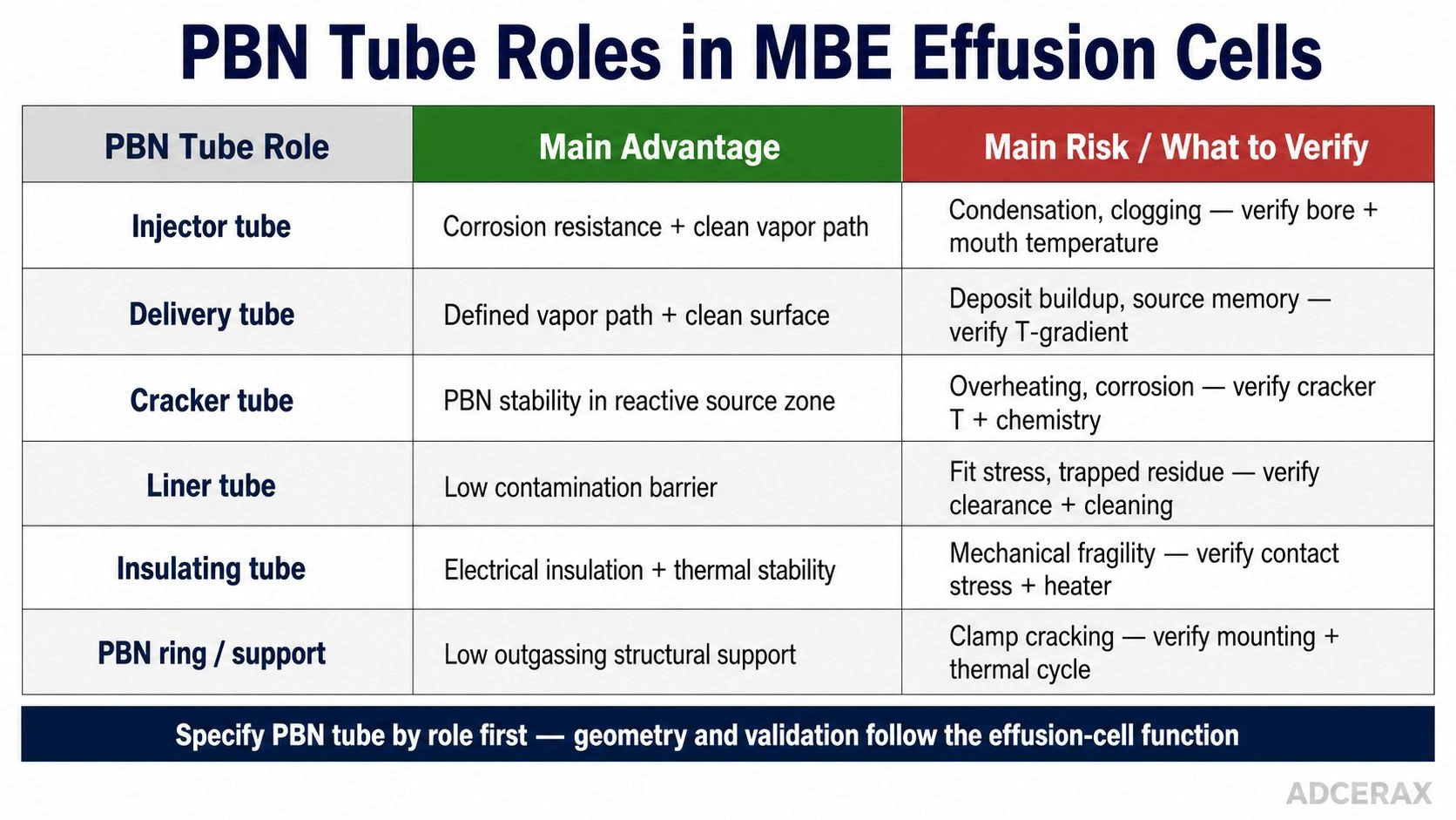
PBN tube selection in MBE effusion cells should start from role, because injector, delivery, cracker, liner, insulating, and support tubes each require different geometry, thermal, contamination, and validation checks.
Table 2 — PBN Tube vs PBN Crucible in Effusion Cells:
| Variable | PBN crucible | PBN tube | Engineering implication |
|---|---|---|---|
| Main role | Holds source charge | Guides, injects, cracks, lines, or supports | Specify role before material |
| Key geometry | Volume, lip, cone, wall profile | OD, ID, length, bore, mouth, seat | Tube geometry affects conductance |
| Main risk | Source wetting, spitting, residue | Condensation, clogging, alignment, deposits | Failure modes differ |
| Exposure | Source melt/solid contact | Vapor path or heater/source contact | Chemistry may be more reactive in tube |
| Validation | Outgassing, flux, source stability | RGA, flow/flux, residue, thermal profile | Test as installed |
| Replacement trigger | Source memory, cracks, residue | Clogging, deposits, cracking, RGA background | Track separately |
Injector tubes in valved or corrosive source cells. In valved effusion cells and corrosive cracker sources, the vapor path from the crucible to the growth chamber passes through a series of hardware elements. Published specifications for a valved corrosive cracker source explicitly list the crucible, valve mechanism, injector tube, and cracker as PBN components — specifically because these source-facing parts are exposed to corrosive evaporants and must minimize contamination and material attack.
Cracker tubes for reactive or molecular species. Cracker sources for As₂/As₄, P₂, Sb₂, Sb₄, and selected dopant species use a separate heated cracking zone where the high-temperature BEP is converted from higher-molecular to lower-molecular species. The cracker tube defines this zone, and it operates at temperatures above the main source temperature — sometimes considerably above 900°C — while exposed to reactive vapor. PBN's combination of thermal stability and chemical inertness is specifically needed here.
Delivery tubes and condensate-return paths. Patent literature describing effusion cell designs shows configurations where a crucible, delivery tube, and supply tube are arranged to both carry vapor from the source and allow condensate to return to the reservoir. This shows that tube geometry is not just about mechanical fit — it actively participates in managing the condensation and vapor balance inside the source.
Insulating tubes and PBN rings around heater assemblies. Many effusion cell heater assemblies use PBN tubes or rings to provide electrical insulation between the heater wire and the metallic source body. These insulating tubes do not directly contact the source vapor, but they operate at high temperature and must maintain dimensional stability and electrical insulation through thousands of thermal cycles.
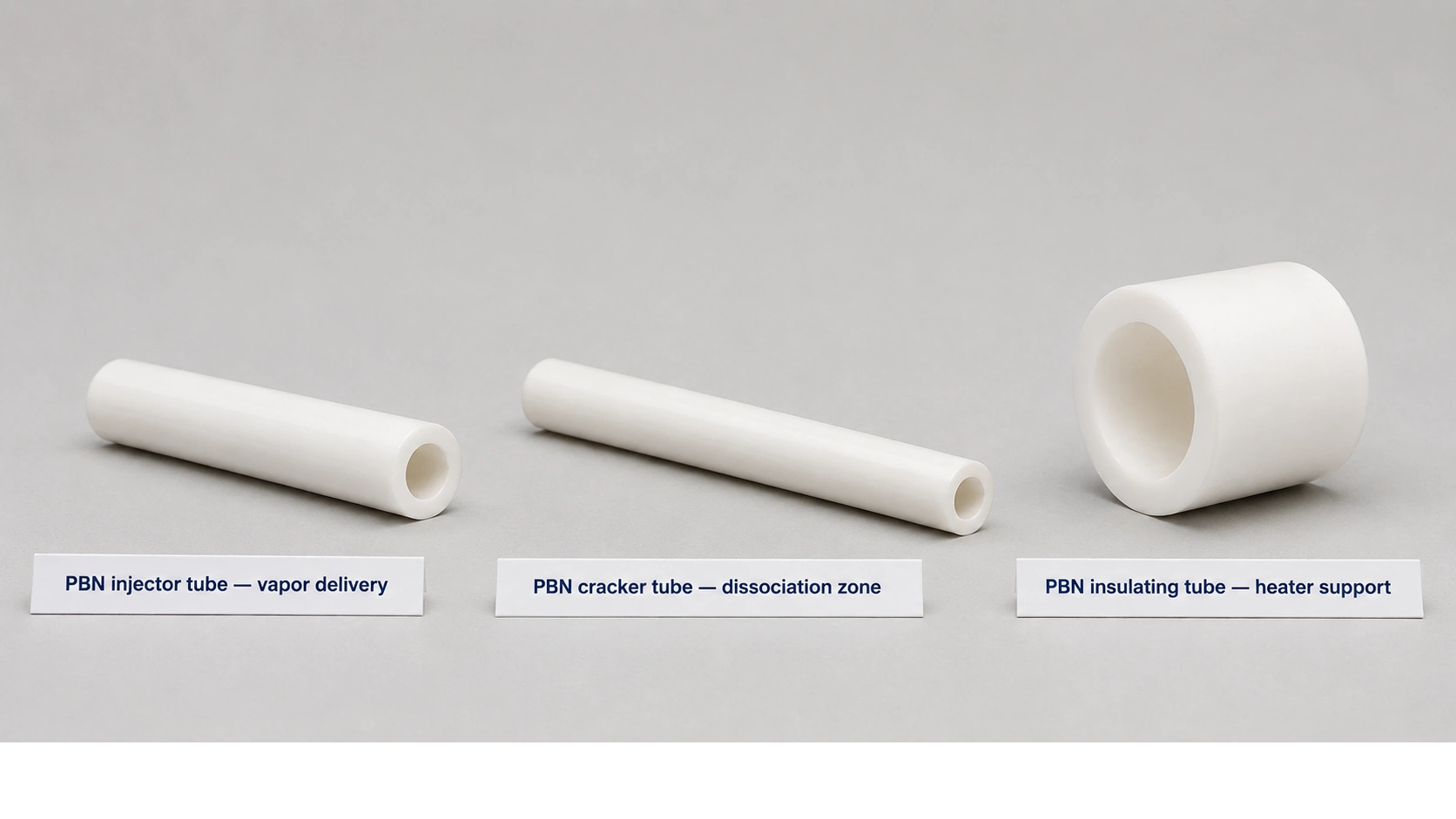
Injector tubes, cracker tubes, and insulating tubes represent different PBN tube functions inside effusion cells — vapor delivery, dissociation-zone stability, and heater support should not be specified as one generic tube.
Why PBN is chosen for MBE source tubes
After mapping the hardware positions where PBN tubes appear, the material-selection argument for PBN over alternatives becomes specific.
[CITE: Published MBE effusion-cell component guidance from a specialized MBE hardware supplier describes PBN as an accepted crucible and source-component material for MBE because of high purity, chemical inertness, thermal stability, low outgassing, non-wetting behavior, and long lifetime, with practical use temperatures up to 1500°C depending on chamber pressure — while Shin-Etsu's PBN materials description confirms that PBN is produced by chemical vapor deposition at high temperature and has superior chemical stability and heat resistance compared with conventional sintered BN — confirming that PBN's advantage over hot-pressed BN for MBE source tubes is specifically the combination of CVD-derived density, purity, and low outgassing that hot-pressed BN cannot provide at the same level due to its granular, potentially binder-containing microstructure.]
Low outgassing under UHV source conditions. The MBE growth chamber operates at base pressures better than 10⁻¹⁰ torr. Any material in the source assembly that outgasses — releasing water, hydrocarbons, or other species — contributes to the chamber background and can incorporate into the growing epitaxial film. PBN's CVD-grown dense structure has far lower open porosity than hot-pressed BN, which means fewer sites to trap and later release atmospheric species during bake-out and operation.
High purity and low metal-contamination risk. For III–V and II–VI MBE, even trace metal contamination at the parts-per-billion level in the source component can affect carrier concentration, mobility, and optical properties in the grown material. PBN produced by CVD can achieve trace metal levels that make it suitable for source-facing positions in III-arsenide and III-nitride MBE. The hot-pressed BN vs PBN comparison at ADCERAX distinguishes the two routes by manufacturing method, purity, density, and gas permeability.
Corrosion control for Sb, Te, Mg, As, P, and other reactive sources. Some MBE source materials are aggressively reactive toward non-PBN ceramics, metals, and even some grades of hot-pressed BN. Antimony, telluride, phosphorus, and magnesium sources, when operated at high temperature, can react with many surfaces they contact. PBN's combination of chemical inertness and high-temperature stability makes it the standard choice for source-facing tubes and injectors in these corrosive source configurations.
Thermal anisotropy and source-zone heat distribution. Published PBN tube product descriptions note that the CVD layered structure gives PBN anisotropic thermal conductivity — higher in the plane perpendicular to the CVD deposition axis. For a source tube positioned in the effusion cell, this anisotropy can affect how heat moves from the heater through the tube wall to the source vapor. Understanding and specifying the tube orientation relative to the heater geometry can improve source thermal stability.
Tube geometry controls flux, condensation, and source stability
After confirming PBN as the correct material, the geometry specification determines whether the tube actually solves the source stability, condensation, and cleanliness problem.
Bore diameter and vapor conductance. The bore of an injector or delivery tube defines the conductance available for vapor flow from the crucible to the growth chamber. A tube that is too narrow for the source temperature and flux rate will impede the beam, reducing effective deposition rate and creating pressure gradients that can cause local condensation. A tube that is too wide may allow excessive backstreaming or cross-contamination between adjacent source cells.
Tube length and vapor residence time. For cracker tubes, the length of the heated zone determines how much time the vapor spends at cracking temperature — and therefore the efficiency of dissociation from the higher-molecular to the lower-molecular species. For delivery tubes, length determines the temperature gradient from the hot crucible region to the cooler valve or aperture region, which controls where condensation is most likely to occur.
Heated lip and mouth temperature control condensation. The most common cause of delivery or injector tube clogging in production MBE is insufficient heating at the tube mouth or lip. If the outermost section of the tube — the region closest to the valve aperture or growth-chamber interface — is significantly cooler than the source temperature, condensate accumulates and can partially or fully block the vapor path. Some valved source designs address this with a separately heated lip zone; the tube geometry must support this heater configuration.
Cracker tube geometry and dissociation zone stability. In As₂ or P₂ crackers, the cracker tube forms the high-temperature zone where As₄ or P₄ molecules are dissociated. The tube must withstand not only the cracker temperature but also the reactive vapor at that temperature. If the cracker tube's bore is too small or its wall too thin, thermal stress from the combination of high temperature and reactive vapor exposure can initiate cracking.
The boron nitride crucible and custom PBN geometry range at ADCERAX covers both standard PBN source crucibles and custom tubular geometries for injector, delivery, liner, and cracker applications, with custom bore, wall, mouth, and seat dimensions matched to specific effusion cell assemblies.
Do not misdiagnose effusion-cell problems as PBN tube failure
When an MBE effusion cell shows flux instability, increasing RGA background, tube mouth deposits, particle events, or source memory, the PBN tube material is one of several possible causes — and diagnosing it as the primary cause before checking the thermal design, source chemistry, and chamber condition leads to unnecessary component replacement without resolving the actual problem.
Condensation vs PBN tube wetting failure. If the delivery or injector tube shows deposits accumulating at its mouth or in a cooler mid-section, the cause is almost certainly insufficient heating of that section rather than a failure of the PBN surface. PBN's non-wetting behavior reduces the adhesion of most metallic and compound-semiconductor evaporants, but if a surface is cool enough to be below the local vapor pressure of the evaporant, condensation occurs on any material regardless of its surface energy.
Source material outgassing vs PBN outgassing. When RGA background peaks increase after loading a new source charge, the first diagnostic question is whether the source material itself — rather than the PBN tube — is the outgassing source. Many source materials, even nominally high-purity grades, carry oxide layers, adsorbed water, or surface contamination that desorbs during initial heating. Running the source through a gradual bake-out sequence and monitoring RGA before reaching the evaporation temperature separates source-material outgassing from tube outgassing.
Overheating and PBN decomposition risk. Published MBE maintenance experience notes that pushing source cells above certain temperature thresholds — particularly for silicon or high-temperature dopant sources — can cause the PBN component to decompose, releasing nitrogen species that appear in the RGA and can be misinterpreted as a new source signal. The practical temperature limit for PBN decreases as chamber pressure rises, which means cells operated at elevated background pressures face more stringent temperature constraints than those operated at deep UHV.
The Failure Diagnosis Matrix below maps observed effusion-cell problems to better diagnostic questions:
| Observed problem | Common assumption | Better diagnostic question |
|---|---|---|
| Flux drops over time | PBN tube is degrading | Is source condensing in a cooler tube section? |
| RGA background increases | PBN tube outgassing | Was chamber, heater, source material, or packaging checked? |
| Tube mouth deposits | PBN reaction | Is lip temperature too low or source vapor supersaturated? |
| Cracker tube cracks | Bad PBN quality | Was thermal expansion constrained or heating too rapid? |
| New particles appear | PBN shedding | Is deposit flaking, shutter wear, or source residue responsible? |
| Source memory appears | Tube material contaminated | Was the tube reused for incompatible sources? |
| N signal appears at high temperature | Source flux only | Is PBN overheating or decomposing at the source condition? |
Diagnosis should be based on RGA comparison, source temperature history, condensation pattern inspection, and chamber audit before any tube component change is specified.
RFQ checklist for PBN tubes in MBE effusion cells
A complete RFQ for PBN tubes in MBE effusion-cell applications must provide the source-assembly context and the tube role — without both, the supplier cannot confirm bore size, wall thickness, mouth geometry, or validation requirements for the specific source configuration.
[CITE: Engineering and MBE source hardware guidance on PBN tube specification for effusion-cell applications confirms the complete RFQ sequence: effusion-cell brand and model or source assembly drawing, tube role (injector/delivery/cracker/liner/insulating support), source material, operating temperature and bake-out temperature, base pressure and operating pressure, tube OD/ID/length/wall and bore tolerance with mouth geometry, direct evaporant or radical exposure status, RGA species of concern including H₂O/CO/CO₂/hydrocarbons/N-related and source-specific fragments, cleaning method and packaging cleanliness, and validation plan including empty-tube bake-out, RGA comparison, source-loaded stability test, and post-run residue inspection — because source material, tube geometry, and thermal design together determine whether the PBN tube maintains clean, stable, clog-free vapor delivery, and a supplier who receives only ""PBN tube, 15mm OD, 100mm long"" cannot confirm bore, mouth geometry, or validation requirements without the remaining source-assembly context.]
| RFQ field | Why it matters | Recommended wording |
|---|---|---|
| Effusion-cell model | Defines fit and thermal layout | ""Brand/model or drawing of source assembly"" |
| Tube role | Determines geometry and exposure | ""Injector/delivery/cracker/liner/support tube"" |
| Source material | Primary compatibility driver | ""Ga, In, Al, As, Sb, Te, Mg, Si, Be, P, etc."" |
| Temperature | Controls outgassing, condensation, and PBN limit | ""Operating, bake-out, peak, ramp profile"" |
| Vacuum level | Defines cleanliness requirement | ""Base pressure and operating pressure"" |
| Tube geometry | Controls vapor conductance and fit | ""OD, ID, length, wall, bore tolerance, mouth geometry"" |
| Direct exposure | Defines surface cleanliness risk | ""Direct evaporant/radical exposure yes/no"" |
| RGA limits | Makes outgassing measurable | ""H₂O, CO, CO₂, hydrocarbons, N-related, source fragments"" |
| Cleaning/packaging | Controls particles and moisture | ""Clean pack, dry pack, solvent compatibility, no particle shedding"" |
| Validation | Confirms real suitability | ""Empty bake, RGA, source trial, residue inspection"" |
RFQ fields are the minimum for a PBN MBE source tube inquiry; add cracker zone temperature, dissociation species, valve interface geometry, and heater contact specification for cracker or valved source designs.
For new source configurations — new source material, new effusion-cell model, or first-time use of a PBN tube in a previously all-metal source position — running the empty tube through the full bake-out and measuring RGA before loading the source is the minimum qualification standard before production growth.
Evaluating PBN tubes for MBE effusion cells? Share your effusion-cell model, source material, tube role, source temperature, bake-out profile, vacuum level, tube drawing, bore tolerance, mouth geometry, RGA limits, and condensation history. ADCERAX can review whether a PBN injector tube, delivery tube, cracker tube, liner, or custom source-facing PBN component fits the process; turnaround depends on inquiry complexity — no commitment required at this stage.
Frequently Asked Questions
What are PBN tubes used for in MBE effusion cells?
PBN tubes in MBE effusion cells may serve as injector tubes that guide vapor toward the source outlet, delivery tubes that transfer evaporated material, cracker tubes that provide the heated dissociation zone for reactive species, liner tubes that separate source vapor from the source holder, and insulating tubes or rings that provide electrical isolation for heater assemblies. Their function is distinct from the PBN crucible, which primarily holds the source charge.
Why use PBN instead of hot-pressed BN for MBE source tubes?
PBN is CVD-grown, dense, high-purity, and low outgassing — properties that hot-pressed BN cannot provide at the same level due to its granular, potentially porous, and binder-containing microstructure. Published MBE source component descriptions confirm PBN as the standard choice for UHV source-facing tubes because of high purity, chemical inertness, thermal stability, low outgassing, non-wetting behavior, and long lifetime.
Which MBE sources benefit most from PBN injector or cracker tubes?
Reactive, corrosive, or vapor-path-sensitive sources — including Sb, Te, Mg, As, P, and selected dopant sources — benefit most from PBN source-facing tubes. Published specifications for a valved corrosive cracker source explicitly list the crucible, valve mechanism, injector tube, and cracker as PBN components to minimize corrosion from the reactive source evaporants.
What causes PBN source tubes to clog in MBE systems?
The most common cause of injector or delivery tube clogging is insufficient heating at the tube mouth or lip, which allows source vapor to condense in the cooler section. This is a thermal design problem rather than a PBN material failure — PBN's non-wetting behavior reduces adhesion, but below the local condensation temperature, any surface will accumulate deposits regardless of material.
Can PBN tubes be overheated in MBE effusion cells?
Yes. PBN has practical temperature limits that decrease as chamber pressure rises. Published MBE hardware guidance notes that PBN can be used up to 1500°C under appropriate conditions, but practical limits for specific source configurations are lower. Published MBE maintenance commentary also notes that overheating PBN in certain source cells can release nitrogen species detectable by RGA, which can be misinterpreted as source-related signals.
What information should I send to a supplier for a PBN MBE source tube?
Send the effusion-cell model or source assembly drawing, the tube role, source material, operating temperature and bake-out temperature, base and operating pressure, tube OD/ID/length/wall and bore tolerance, mouth geometry, whether direct evaporant exposure occurs, RGA species of concern, cleaning method, packaging requirements, and the validation plan — including empty-tube bake-out, RGA comparison, source-loaded stability, and post-run residue inspection.
"