A worn sample can start a replacement project, but it should not be copied as an undamaged master. Wear may reduce a shaft diameter, enlarge a bore, remove a coating, round an edge, or distort a seating face. First separate trustworthy surfaces from damaged ones. Reconstruct critical dimensions using symmetry, mating components, functional clearances, and service conditions. Confirm material through appropriate evidence rather than appearance alone. Create a controlled drawing, manufacture a first article, inspect its critical interfaces, and complete a controlled application trial before approving repeat production.
Use this reconstruction workflow:
- Define whether the goal is duplication, restoration, or redesign.
- Photograph and preserve the sample before cleaning or sectioning.
- Classify each surface as trustworthy, damaged, or uncertain.
- Select measurement methods by feature and required uncertainty.
- Separate measured, reconstructed, and redesigned dimensions.
- Rebuild functional fits from mating components and assembly duty.
- Identify the material with multiple appropriate evidence sources.
- Approve a controlled drawing and material route.
- Manufacture, inspect, assemble, and test a first article.
- Validate a pilot batch before freezing repeat-production controls.
1. Should the Part Be Duplicated, Reconstructed, or Redesigned?
“Make another one like this” can describe three different projects. Select the route before scanning or quoting custom ceramic replacement parts, because the route determines which sample measurements are authoritative.
Duplicate the verified original when reliable surfaces, an unused spare, or a controlled drawing corroborate the geometry; the existing material and life are acceptable; and interchangeability must be preserved.
Restore original design intent when sliding, sealing, locating, or load-bearing surfaces are worn; geometry is missing; no controlled drawing survives; or original dimensions must be inferred from mating components, symmetry, and clearance.
Redesign the replacement when the same failure recurs, the material is attacked by wear or corrosion, the mounting damages a ceramic part, or metal-to-ceramic conversion is under review.
| Project evidence or condition | Correct route | Primary risk |
|---|---|---|
| Unworn sample plus controlled OEM drawing | Duplicate verified original | Revision or material mismatch |
| Worn sample plus sound mating components | Restore design intent | Incorrect wear compensation |
| Broken part with repeated or symmetric geometry | Reconstruct missing features | Hidden asymmetry |
| Repeated failure under unchanged duty | Redesign after root-cause review | Reproducing the failure |
| Metal part with persistent corrosion or wear | Evaluate ceramic conversion | Expansion, impact, and mounting differences |
| Unknown safety-critical component | Stop for responsible engineering approval | Unverified replacement risk |
Do not proceed directly to manufacture when the application is unknown, no engineer can approve inferred dimensions, pressure or lifting certification is involved, or reproduction rights are unresolved. ADCERAX reviews replacement ceramic components and justified metal-to-ceramic conversions. A metal sample requiring another metal part normally belongs with a qualified machine shop or foundry.
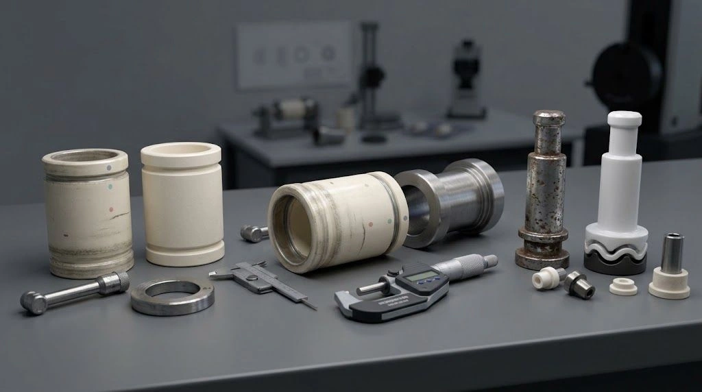
The three physical routes prevent a worn sample from being treated automatically as the original design authority.
2. How Should the Sample Be Preserved and Classified?
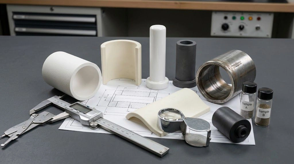
Do not aggressively clean, polish, grind, or section the part before documentation. Deposits, discoloration, fracture markings, wear bands, and transferred material may indicate load direction, temperature zone, motion, or chemical attack. Photograph the complete part from multiple directions with a scale and identifier. Record its orientation in the equipment and collect every ceramic fragment.
For a brittle fracture, protect fracture faces from rubbing or contamination. ASTM C1322-25 provides a systematic approach to locating and characterizing fracture origins in advanced ceramics and notes that machining, handling, impact, wear, oxidation, and corrosion can introduce origins. The method requires expert interpretation; one fragment does not guarantee a complete conclusion.
| Sample region | Evidence classification | Correct use |
|---|---|---|
| Protected mounting land | Potentially trustworthy | Datum or original-size evidence after confirmation |
| Active sliding surface | Worn | Map material loss; do not copy directly |
| Enlarged bore | Worn | Reconstruct using shaft and required clearance |
| Corroded face | Damaged | Define attack zone and previous envelope |
| Deposited surface | Contaminated | Document or analyze before cleaning |
| Fracture face | Failure evidence | Preserve for origin assessment |
| Symmetric opposite feature | Reconstruction evidence | Infer missing geometry with stated confidence |
| Coated or plated zone | Modified surface | Identify coating and underlying geometry |
The minimum evidence package should contain full-part views, end views, close-ups of damage, installed-position photographs, mating components, scale references, identification markings, and the flow, rotation, load, or hot-side direction. Record previous service life, maintenance, lubrication, cleaning, and failure sequence. Separate observations from assumptions so later inspection does not convert a guess into a drawing requirement.
3. Can a 3D Scan Recover the Original Dimensions?
A scan captures the current surface, including wear, deposits, deformation, and broken edges. It does not automatically identify ideal cylinders, planes, cones, radii, datums, tolerances, fits, or surface texture. A point cloud or mesh is measurement input, not a production-ready drawing.
Use micrometers, bore gauges, and height gauges for accessible sizes. A coordinate measuring machine can establish datum-related geometry. Vision systems suit profiles and small edges. A 3D scanner efficiently records freeform external surfaces. Industrial CT may reveal hidden channels, subject to material density, size, resolution, artifacts, and measurement qualification.
ISO 10360-2:2009, confirmed current in 2026, defines acceptance and reverification tests for Cartesian CMMs using contacting probes to measure linear dimensions. It does not explicitly cover optical probing, and it does not transform worn geometry into original design intent.
| Feature or evidence | Suitable starting method | Key limitation |
|---|---|---|
| Accessible OD, ID, length | Micrometer, bore gauge, height gauge | Limited complex-form information |
| Datum-related holes and shoulders | Qualified CMM method | Needs stable fixturing and datum logic |
| Small profile or edge | Vision system or optical comparator | Line-of-sight and edge-detection limits |
| Freeform exterior | 3D scanning | Captures current geometry |
| Hidden cavity | Industrial CT | Density, size, resolution, artifact limits |
| Flatness or roundness | Dedicated form equipment or qualified CMM | Needs a defined strategy |
| Surface texture | Profilometer | Does not establish flatness or material |
Tag every proposed drawing value in the engineering record: M—Measured for reliable sample surfaces; R—Reconstructed for values inferred from mating parts, symmetry, or functional clearance; and D—Redesigned for intentional changes. The tags may be removed from the released drawing, but retaining them during review exposes uncertainty and assigns approval responsibility. This distinction keeps dimensional uncertainty visible during supplier review, approval, and later validation.
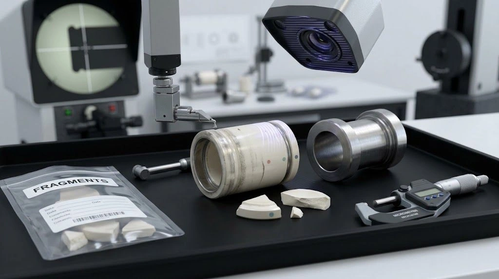
Multiple measurement methods describe the surviving evidence; engineering reconstruction still determines the replacement definition.
4. How Are Fits and Unknown Materials Reconstructed?
A worn shaft, pin, or plunger usually measures smaller than its original size; a worn bushing, sleeve, or cylinder usually measures larger. Copying both reproduces excessive clearance. Rebuild the relationship from the less-worn member, an unused mating component, equipment documents, functional movement, sealing need, lubricant or coating thickness, and operating-temperature effects.
Ask which surface locates the part, which carries load, which slides or seals, whether the mating component is also worn, and which clearance can be verified during assembly. ISO 1101 defines geometrical-specification language, while ISO 5459 defines datum-system rules. Use them to express the reconstructed relationship rather than applying blanket tolerances.
Material identification also needs layered evidence. Appearance, magnet response, or density may narrow candidates but rarely confirms a grade. For metals, ASTM E1476-04(2022) describes quantitative spectrometric methods such as X-ray fluorescence and optical emission, plus qualitative screening methods. Results still require suitable calibration, sample preparation, and interpretation.
| Evidence | Metal sample | Ceramic sample | Boundary |
|---|---|---|---|
| Appearance or density | Preliminary alloy clue | Family or porosity clue | Grades can overlap |
| Hardness | Heat-treatment or alloy evidence | Grade or process evidence | Surface condition influences result |
| XRF | Alloy-element screening | Major-element screening | Limited for light elements and phase |
| Optical emission | Quantitative metal chemistry | Not the usual ceramic route | Requires suitable surface preparation |
| XRD | Selected phase information | Ceramic phase identification | Does not reveal full process history |
| SEM/EDS | Local chemistry and microstructure | Local chemistry and microstructure | Local region may not represent bulk |
| Fractography or sectioning | Failure and heat-treatment clues | Grain, porosity, fracture clues | Potentially destructive |
| Certificate or supplier code | Strong documentary evidence | Strong documentary evidence | Verify revision and authenticity |
When metal repeatedly corrodes, contaminates, or loses clearance through wear, alumina, zirconia, silicon carbide, or silicon nitride may merit review. Conversion is not a material substitution on the old metal drawing. Reassess thermal-expansion mismatch, interference fits, tensile stress, impact, sharp corners, threads, thin walls, compliant mounting, edge radii, counterface, and electrical or thermal function. Metal that must flex, conduct, or absorb impact may remain the better choice.
5. How Should the First Article Be Validated?
Create a controlled drawing containing part number, revision, approved material, nominal geometry, functional datums, CTQ dimensions, surface zones, edge conditions, inspection methods, special treatments, and assembly requirements. A custom ceramic manufacturing review should resolve accessible grinding surfaces, as-fired regions, mounting risk, and material route before production.
Use these stage gates:
- Evidence review: approve the M, R, and D classifications.
- Drawing approval: authorize reconstructed geometry and material direction.
- First article: manufacture a limited quantity by the intended route.
- Dimensional inspection: verify CTQ size, form, orientation, position, and texture.
- Bench assembly: check insertion, seating, clearance, movement, and sealing without force.
- Application trial: run under defined load, temperature, medium, pressure, motion, and cycles.
- Post-test inspection: check wear, leakage, fracture, dimensional change, and counterface damage.
- Pilot batch: confirm repeatability beyond one specially handled sample.
- Specification freeze: approve revision, route, inspection baseline, and change control.
ISO 14253-1 addresses conformity decisions when measured values approach specification limits and measurement uncertainty matters. Agree on the acceptance rule and required ceramic dimensional inspection before evaluating the first article.
| RFQ group | Information to send |
|---|---|
| Project goal | Duplicate, restore, correct failure, or convert material |
| Sample condition | Worn, corroded, deposited, deformed, chipped, broken |
| Evidence | Samples, fragments, photographs, drawings, manuals, codes |
| Installation | Orientation, supports, fasteners, mating components |
| Function and CTQs | Locate, seal, slide, rotate, insulate, guide, contain |
| Material and service | Known grade or analysis request; duty and environment |
| Quantity | First article, pilot batch, spares, annual demand |
| Approval | Drawing, inspection, assembly, and application-trial requirements |
| Packaging | Edge protection, cleanliness, sample-return instruction |
| Authorization | Confirmation that reproduction and use are permitted |
Send photographs before cleaning, the physical sample and fragments, mating dimensions, operating conditions, failure history, and quantities. ADCERAX can review a ceramic replacement or metal-to-ceramic conversion. General metal remanufacture, regulated safety approval, pressure-code reconstruction, and legal reproduction authorization remain outside this supply review.
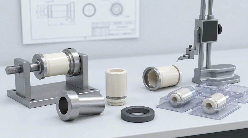
First-article and pilot validation convert reconstructed evidence into a controlled repeat-production specification.
Frequently Asked Questions
Can a worn sample be copied exactly?
It can be measured exactly in its present condition, but that condition may include wear, corrosion, deposits, distortion, or missing material. Reconstruct functional dimensions from trustworthy surfaces, mating components, symmetry, and service requirements before approving a production drawing.
Is a 3D scan sufficient to manufacture a replacement?
Usually not by itself. A scan captures current surface coordinates but does not define original design intent, datums, tolerances, fit, surface texture, or material. Engineering review must convert the point cloud or mesh into controlled geometry and acceptance requirements.
How can the original size of a worn bore or shaft be recovered?
Use unworn lands, symmetric features, unused mating parts, equipment documentation, and the required operating clearance. Map the worn region rather than selecting one measurement. Mark the resulting value as reconstructed and verify it through first-article inspection and bench assembly.
Can an unknown material be identified from one test?
Rarely with complete confidence. Density, hardness, XRF, optical emission, XRD, microscopy, and documentary evidence answer different questions. Select methods for the suspected metal or ceramic and required confidence, then record limitations instead of claiming an exact grade from appearance alone.
Can a worn metal part be converted directly to ceramic?
Not by copying the metal drawing. Ceramic conversion requires review of expansion mismatch, interference, tensile stress, impact, edge geometry, mounting compliance, counterface, and thermal or electrical function. The conversion is justified only when it addresses a documented failure without creating a new one.
When can repeat production be released?
Release it after the reconstructed drawing and material route are approved, a first article meets CTQs and assembly checks, and a controlled application trial shows acceptable behavior. A pilot batch should then confirm dimensional and process repeatability before the specification is frozen.