Alumina tubes crack in high-temperature furnaces when thermal gradients, restrained expansion, mechanical loading, or chemical attack create tensile stress above the ceramic's fracture tolerance. The tube may be far below alumina's melting point and still fail because ceramics are weak under tensile stress and sudden temperature differences. Prevention depends on controlled ramp and cooling rates, one-end-free expansion, correct support, suitable wall thickness, clean handling, and replacement specifications matched to furnace temperature, atmosphere, and load.
That last point is the most commercially important: cracking is usually a system problem. A higher-purity replacement tube will not fix a fast cool-down, a two-end rigid clamp, or a tray pressing against the lower wall of a horizontal furnace. The failure cause must be identified before a replacement is specified — or the same failure will repeat.
Alumina tube cracking in high-temperature furnaces is a system failure — crack location, furnace orientation, end restraint, and thermal profile all contribute, and each must be checked before specifying a replacement.
The alumina ceramic tubes for furnace, thermocouple protection, and instrumentation applications described in this guide — 96%, 99%, and 99.7% Al₂O₃ grades up to 1700°C — are the products most commonly involved in the failure scenarios and prevention measures below.
What crack pattern are you seeing?
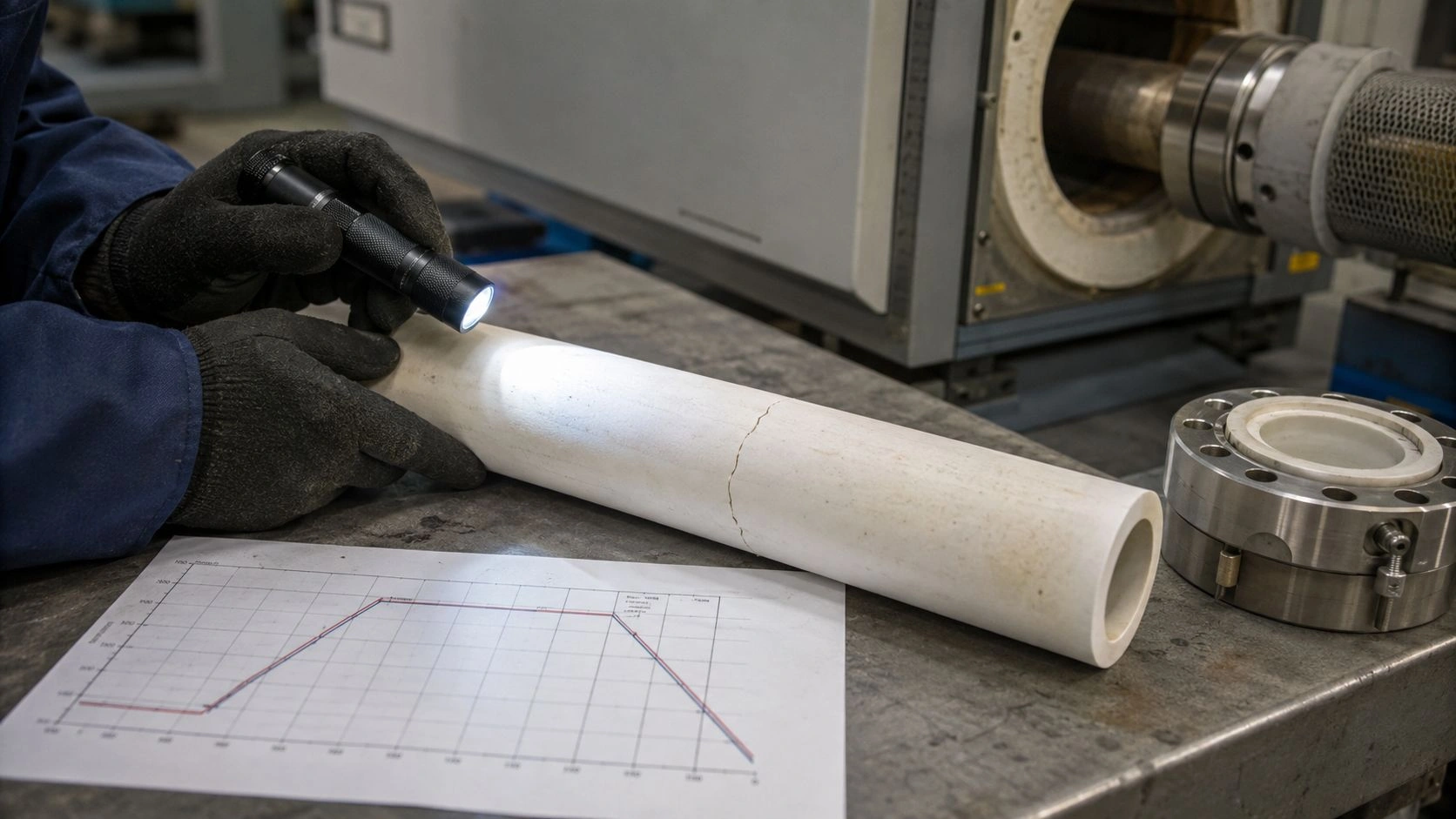
Before attributing a cracked alumina furnace tube to material quality or purity grade, classify the crack by location. Crack location is the most reliable first indicator of failure cause — and it points directly to the prevention action needed before specifying a replacement.
The Crack Pattern Diagnostic Matrix below maps the five most common crack patterns to their likely causes:
| Crack pattern | Likely cause | What to check first | Prevention action |
|---|---|---|---|
| Crack near furnace wall transition | Thermal gradient between hot zone and cold end | Hot-zone length, insulation transition, ramp profile | Add controlled ramp / soak; reduce abrupt cooling |
| Crack near end seal | Axial restraint or uneven clamping | End cap pressure, seal alignment, expansion allowance | Fix one end only; allow expansion at the other end |
| Crack on bottom side of horizontal tube | Point loading or sag-related stress | Support contact, internal load, tray placement | Use distributed refractory supports |
| Edge chips near open end | Handling or installation impact | Storage, unpacking, insertion method | Add handling SOP and protective packing |
| Surface pitting followed by later cracking | Chemical attack or deposits | Atmosphere, sample reaction, residue | Verify chemical compatibility and cleaning procedure |
Crack location provides a starting hypothesis; verify with furnace history, ramp profile, and installation review.
Published AZoM guidance on ceramic furnace tube failure notes that temperature gradients during processing can reduce tube strength, and specifically recommends one-end restraint control, careful internal support, and attention to tube diameter and wall thickness to reduce gradient-related failure risk. That published guidance supports the same crack-location diagnostic logic: the pattern shows where the stress concentration was highest.
Hot-zone cracks vs cold-end cracks
A crack that appears at the boundary between the hot zone and the cooler furnace end section — or at the tube wall transition — reflects a steep axial temperature gradient. The hot section expands; the cooler section resists; the stress is highest at the transition. The prevention action is to slow the ramp rate, add a soak period at intermediate temperatures, and ensure that the insulation transition is not abrupt.
Support-point cracks vs handling chips
A crack running longitudinally along the bottom of a horizontal tube, or located at a specific contact point with an internal support or sample holder, indicates point loading rather than global thermal shock. A chip near the tube opening that was present before the first run — or that appeared during insertion — is handling damage, not in-service thermal failure. Both require different corrective actions: point-loading failures are prevented by distributing internal support across longer contact lengths, while handling failures require better protection during storage and installation.
Why thermal gradients crack alumina below its melting point
The confusion that causes most repeat failures after tube replacement is this: alumina has a very high melting point, and engineers assume this makes it tolerant of any high-temperature use. It does not. Alumina fails under tensile stress, not under melting conditions.
Published NIST property data for sintered alpha-alumina reports a melting point near 2050°C — confirming that the material is not melting when it cracks in furnace service below 1700°C. The same NIST data source documents creep behavior for sintered alpha-alumina at temperatures in the 1200–1800°C range, confirming that sustained high-temperature stress, load, and time still matter far below the melting point. [CITE: NIST Ceramics Data Portal property data for sintered alpha-alumina documents both the melting point (~2050°C) and creep behavior at 1200–1800°C, confirming that mechanical stress and thermal gradient failure mechanisms are active at normal furnace operating temperatures, not only near the melting point.]
The failure mechanism is straightforward: when one part of the tube heats or cools faster than another, the difference in thermal expansion creates strain. In a brittle ceramic material, that strain becomes tensile stress. When the tensile stress exceeds the ceramic's fracture tolerance — even briefly, during a fast ramp or uncontrolled cool-down — the tube cracks.
Published ASTM C1525 addresses thermal shock resistance of advanced ceramics by measuring strength reduction after controlled water quenching. The standard confirms that thermal shock durability depends not just on temperature but on the combination of mechanical properties, thermal conductivity and diffusivity, heat transfer, and geometry — which is why two alumina tubes with the same purity grade can have different thermal shock tolerance depending on diameter, wall thickness, and the specific furnace heating profile they experience.
Melting point is not the operating limit
The operating limit for an alumina tube in furnace service is determined by the combination of maximum temperature, ramp rate, temperature gradient across the tube wall and length, load, and end restraint — not by the melting point alone. A tube that would survive indefinitely at stable temperature may crack within a few cycles under rapid heating or cooling at a fraction of its melting point.
Why cooling often breaks tubes more than steady heating
During steady-state heating, the tube wall reaches thermal equilibrium and gradients diminish. During cooling — especially if the furnace door is opened hot, cooling gas is introduced, or the ramp-down is uncontrolled — the outer surface cools faster than the wall interior and the cold ends cool faster than the hot zone. Those re-established gradients under cooling create tensile stress on the outer surface and at the gradient transitions, which is why many alumina tube failures occur on cool-down rather than during the heating phase.
Thermal shock or misdiagnosis? Four failure modes that look similar
Not every cracked alumina tube failed because of thermal shock. Replacing a tube with a higher-purity grade and repeating the same ramp profile, end-seal design, and support arrangement will reproduce the same failure. The four most common failure modes that produce similar crack appearances require different corrective actions:
Thermal shock produces cracks at gradient boundaries — the furnace wall transition, the hot zone ends, or the outer surface at the start of cooling. The pattern typically crosses the tube wall and may propagate circumferentially or axially. Prevention requires slowing the thermal ramp and cooling profile and ensuring soak periods equalize the temperature before rapid transitions.
Axial restraint at end seals produces cracks near the tube ends, often circumferential, particularly when both ends are rigidly clamped and the tube cannot elongate during heating. Even a small amount of thermal expansion constrained by tight end hardware creates stress that accumulates over cycles. Prevention requires securing the tube at one end only and allowing free axial movement at the other.
Point loading from internal trays, boats, and sample holders produces longitudinal cracks on the contact side of horizontal tubes, or local cracks at specific load positions. The contact stress is highest where the internal load rests on the tube wall, and it increases during heating as materials expand. Prevention requires distributing the load with longer support boats, ceramic spacers, or tube-specific internal support systems. Published guidance for alumina ceramic tube selection addresses support design as a functional specification variable, not only a geometry question.
Chemical attack or deposit buildup produces surface roughening or pitting that may be invisible initially but generates local stress when residues bond to the tube, expand at different rates, or react with the ceramic. Prevention requires confirming atmosphere compatibility with the alumina grade and establishing a cleaning protocol between runs.
The most commercially important correction in alumina tube failure analysis is separating the material failure — where alumina's properties were the limiting factor — from the system failure — where the ramp profile, end seal, support design, or atmosphere would have cracked any tube of the same geometry. Upgrading purity grade resolves the first; only process and installation correction resolves the second.
Chemical residue and atmosphere mismatch
A tube used with samples that decompose into reactive gases, or used in an atmosphere that attacks Al₂O₃ at operating temperature, can show degradation that is misclassified as thermal shock damage. Before specifying a replacement, confirm that the atmosphere and sample chemistry are compatible with the specific alumina grade across the full temperature and cycling range.
Prevention rules for high-temperature alumina furnace tubes
The Prevention Threshold Matrix below maps each failure variable to lower-risk practice, higher-risk condition, and the data needed to confirm the operating boundary:
| Variable | Lower-risk practice | Higher-risk condition | Data to confirm |
|---|---|---|---|
| Ramp rate | Supplier-approved controlled ramp for the specific tube grade and wall | Fast heat-up from room temperature without soak | Tube grade, wall thickness, furnace thermal mass |
| Cooling | Programmed cooling or soak zones; no forced air or door opening while hot | Opening furnace door hot or forced cooling | Furnace SOP and controlled thermal profile |
| End restraint | One fixed end, one expansion-permitted end | Both ends clamped rigidly in hardware | End seal design review |
| Tube size | Diameter and wall thickness matched to gradient exposure | Large OD + thick wall + rapid thermal cycling | Drawing and furnace zone length |
| Internal loading | Distributed contact support over longer boat or support length | Point-loaded tray or heavy sample on tube wall | Load mass and support geometry |
| Material grade | Grade matched to temperature, atmosphere, and gradient conditions | Grade selected only from catalog without operating condition review | COA, density, purity, open porosity test |
Values indicative; verify per ASTM C1525 for thermal shock resistance data on advanced ceramics and ASTM C20 for apparent porosity and bulk density confirmation on supplier-provided alumina grades.
Published operational guidance from AZoM for ceramic furnace tube failure prevention recommends limiting furnace ramp speed — with 60°C per hour cited in a furnace-tube failure-prevention context as a starting reference — along with securing tubes at only one end to allow thermal expansion, avoiding unnecessarily large-diameter thick-wall tube geometries when smaller formats are sufficient, and using appropriate internal supports for loads placed inside horizontal tubes. These operational principles should be treated as starting points, because the actual safe ramp rate for any specific application depends on tube diameter, wall thickness, furnace design, internal load mass, and atmosphere.
For slowing ramp and cooling gradients, some guidance recommends intermediate soak periods at temperatures where differential expansion between tube zones is reduced before continuing the temperature program. The ceramic tubes and pipes category covering alumina, SiC, zirconia, and BN options provides cross-material context where the operating window or thermal shock tolerance of an alternative material may be relevant.
One fixed end, one expansion-permitted end
The single most important installation rule for alumina furnace tubes is that only one end should be mechanically fixed. The other end must be free to move axially as the tube elongates during heating. If both ends are clamped, the tube cannot accommodate its own thermal expansion and the resulting axial compressive or tensile stress — depending on how the hardware loads the tube — accumulates over cycles until fracture.
Horizontal furnace support and internal load control
In horizontal furnace configurations, the tube's own weight creates sag stress over long spans, and any point where internal load contacts the tube wall at a localized area creates additional stress during heating. Published guidance recommends proper internal supports for parts placed inside horizontal furnace tubes. Ceramic fiber supports, cordierite or alumina boats with broad contact surfaces, and appropriately spaced support points reduce the stress concentration that causes longitudinal cracking.
Replacement tube RFQ checklist after cracking
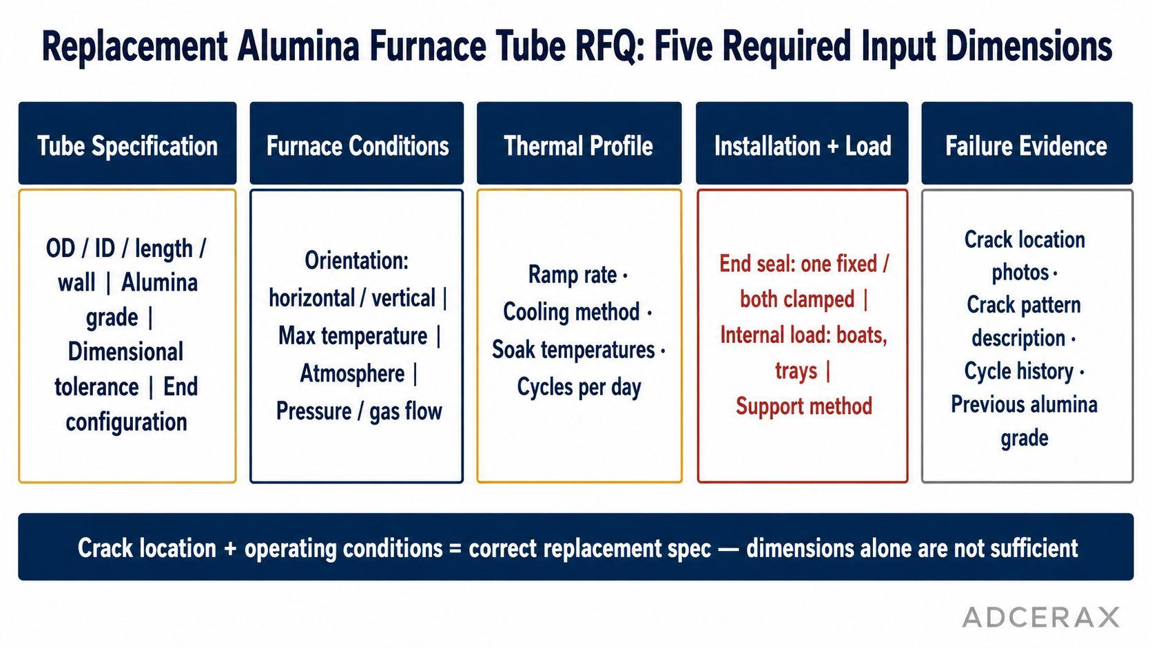
Replacement alumina tube specification requires operating condition data — crack photos, ramp profile, end seal design, and load support — not just tube dimensions.
The RFQ Fields table below captures the minimum information for a replacement alumina furnace tube inquiry that can be reviewed for failure prevention, not just geometry:
| RFQ field | Why it matters | Recommended wording |
|---|---|---|
| OD / ID / length / wall | Controls fit and thermal gradient behavior | "Confirm OD, ID, length, wall thickness, and dimensional tolerance" |
| Alumina grade | Affects temperature capability and impurity baseline | "Quote 99% / 99.7% Al₂O₃ based on furnace temperature and atmosphere" |
| Furnace orientation | Determines sag risk and support requirement | "Application is horizontal / vertical furnace tube" |
| Ramp / cooling profile | Determines thermal-shock exposure | "Review suitability for specified heating and cooling rates; confirm supplier-recommended maximum ramp" |
| End sealing | Determines axial restraint risk | "Confirm expansion allowance at tube ends; identify which end is fixed" |
| Internal load | Determines contact and point-loading stress | "Load includes boats / trays / samples; support layout attached" |
| Failure photos | Helps diagnose repeat failure | "Review crack location photos before recommending replacement grade or geometry" |
Submit this data package before finalizing replacement grade — crack location and operating profile together define the correct specification.
ASTM C20 supports density and apparent-porosity quality requests for shaped refractory ceramics, and ASTM C1525 is the relevant test standard when requesting thermal shock resistance data for advanced ceramic tube grades from suppliers.
The alumina ceramic material grades and product family at ADCERAX provides grade-by-grade purity, temperature, and geometry documentation — the starting point for matching the replacement tube to the confirmed failure analysis rather than to the previous purchase order alone.
[CITE: AZoM ceramic furnace tube failure prevention guidance and expert engineering analysis of alumina tube cracking identify operating-condition controls — ramp rate, end restraint, tube geometry, and support — as the primary determinants of furnace tube service life, which is why requesting crack photos, furnace profile, and installation data from the customer is essential for an engineering supplier to recommend a replacement specification rather than simply repeating the failed part's dimensions.]
Alumina furnace tube cracked? Send the crack location photos, tube drawing, furnace orientation, operating temperature, ramp and cooling profile, atmosphere, end seal design, internal load, and current alumina grade. ADCERAX engineers review the failure pattern and return a replacement tube grade recommendation with ramp guidance, installation notes, and dimensional confirmation for the specific furnace duty; turnaround depends on inquiry complexity — no RFQ commitment required at this stage.
Frequently Asked Questions
Why do alumina tubes crack if alumina has such a high melting point?
Because cracking is caused by tensile stress from thermal gradients, end restraint, point loading, or handling damage — not by the material approaching its melting temperature. Published NIST property data confirms sintered alpha-alumina melts near 2050°C, but ceramics are weak under tensile stress and a tube can fracture far below that temperature if a steep gradient creates differential expansion that exceeds the ceramic's fracture tolerance.
Is thermal shock the most common cause of alumina furnace tube cracking?
Thermal shock is one of the most common causes, particularly during rapid heating or uncontrolled cooling. However, axial restraint at end seals, point loading from internal boats and trays, handling damage that grows during heating, and chemical attack can each produce similar fracture appearances. The crack location is the fastest first diagnostic for distinguishing these failure modes.
What ramp rate should be used for alumina furnace tubes?
There is no universal ramp rate that applies to every alumina furnace tube. Published AZoM furnace-tube prevention guidance cites 60°C per hour as a reference in a specific prevention context. Actual safe rates depend on tube outer diameter, wall thickness, length, furnace thermal mass, internal load, atmosphere, and the supplier's grade-specific guidance. Tubes with larger diameters or thicker walls develop steeper internal gradients at equivalent ramp rates than smaller, thinner-wall tubes.
Why do alumina tubes often crack during cooling rather than during heating?
During controlled heating, the tube wall gradually reaches thermal equilibrium and gradients diminish. During cooling — especially if uncontrolled, if the furnace door is opened hot, or if gas flow is introduced — the outer surface and cold ends cool faster than the wall interior and hot zone. Those reversed gradients during cool-down create tensile stress on the outer surface and at transition zones, making cool-down a higher-risk phase for many furnace tube geometries.
Can higher-purity alumina prevent cracking?
Higher purity may improve high-temperature chemical compatibility and reduce impurity-related performance degradation, but it will not correct rapid cooling, rigid end clamping, point loading from internal hardware, poor internal support in horizontal furnaces, or handling damage. If the root cause is one of these system-level factors, specifying a higher-purity grade will reproduce the same failure in the replacement tube.
What should I send to a supplier when ordering a replacement alumina furnace tube after cracking?
Send crack location photos, the tube drawing with OD/ID/length/wall thickness, furnace orientation (horizontal or vertical), operating temperature, maximum ramp and cooling rate, atmosphere, end seal design and whether one or both ends are clamped, internal load description and support layout, and the current alumina grade. The failure pattern and operating conditions together determine whether the replacement needs a different grade, different geometry, or different installation approach — tube dimensions alone are insufficient for a prevention-based replacement recommendation.