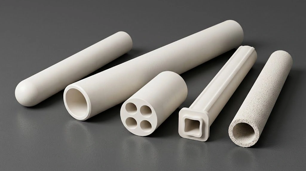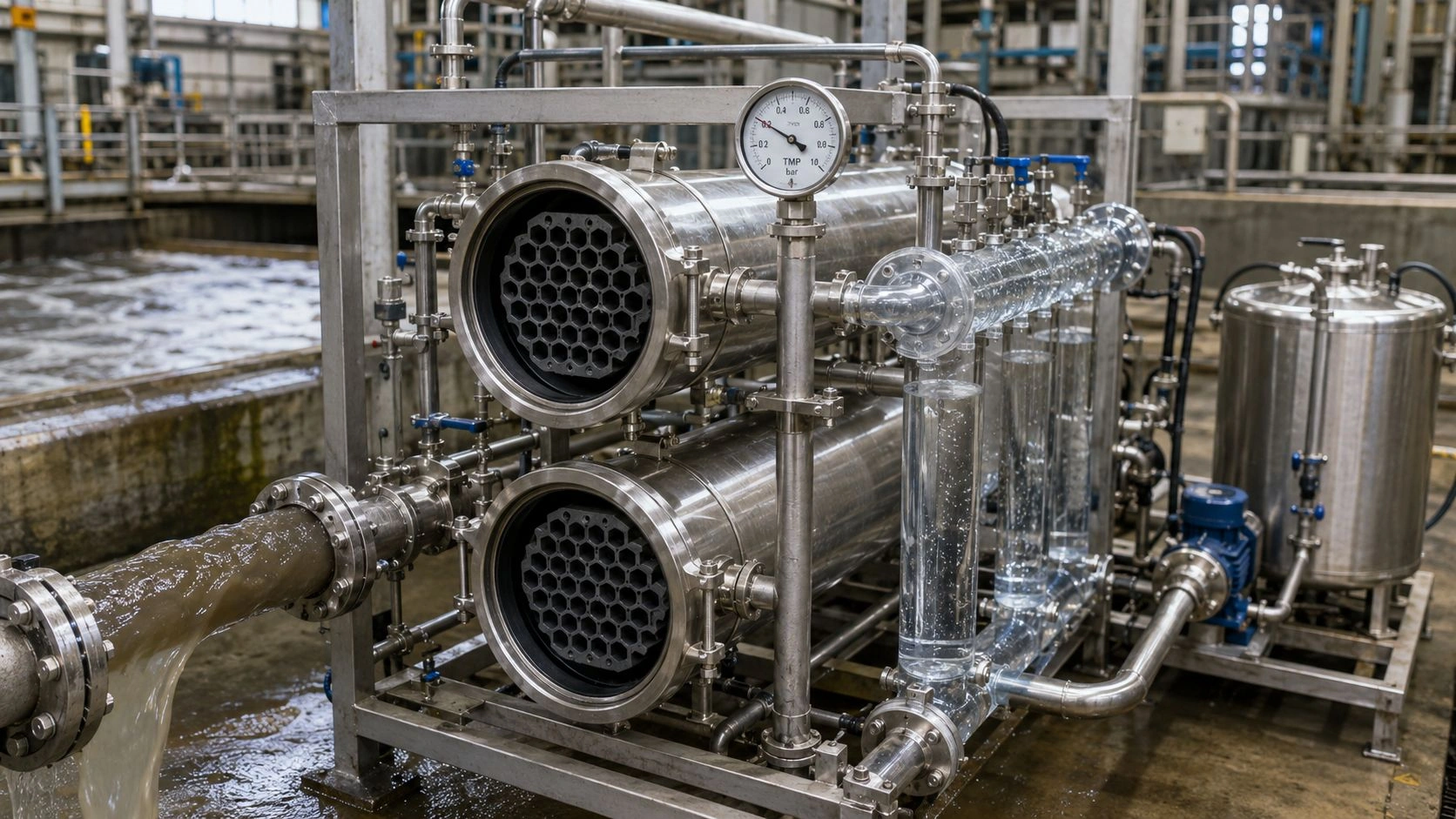
Industrial oil-water emulsions challenge modern wastewater treatment systems through their chemical stability and fine droplet size. Alumina membrane tubes are often selected when polymer membranes struggle with oily emulsions—decide on pore size, TMP/flux, cleaning chemistry, and RFQ fields before locking a design. This article walks the physical chemistry, engineering design, and application checks behind that decision.
Industrial operations that process or refine petroleum, metals, and food products generate wastewater containing oil emulsions stabilized by surfactants. These emulsions resist traditional separation methods, creating persistent compliance issues under EPA discharge standards. The following sections detail how Alumina Membrane Tubes for Wastewater Treatment solve these challenges effectively and reliably.
What Regulatory Limits and Emulsion Characteristics Challenge Conventional Wastewater Treatment?
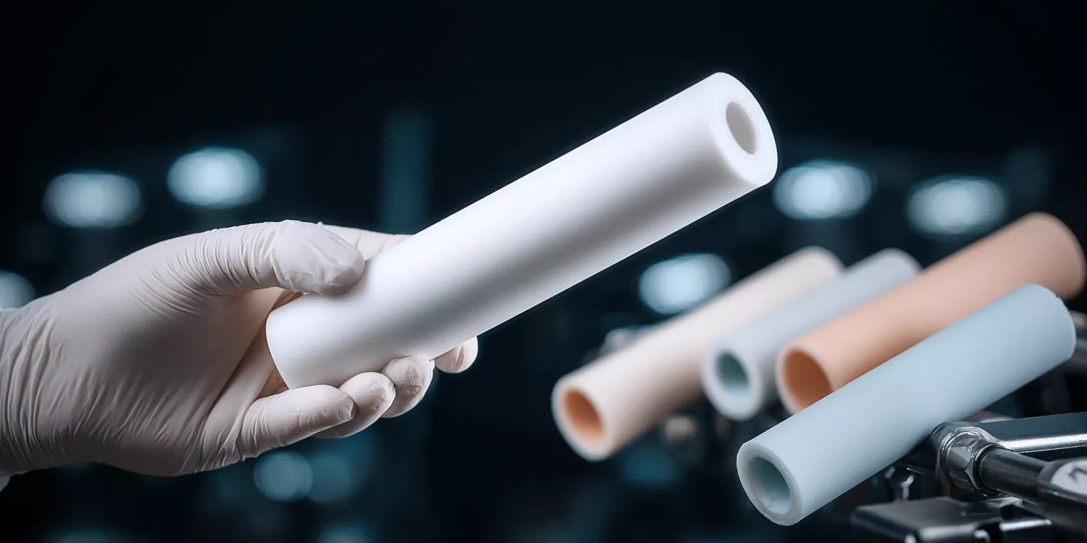
Regulatory standards restrict oil and grease discharge to 10–15 mg/L while maintaining COD below 120 mg/L and BOD₅ under 40 mg/L per 40 CFR Part 437. Emulsified oils smaller than 10 µm remain stable for weeks due to surfactant layers reducing interfacial tension to 5–15 mN/m. Such stability creates energy barriers that prevent droplet coalescence even under mechanical or gravitational separation, emphasizing the need for microporous alumina filter tubes sized for emulsified oil—confirm pore band and TMP on the RFQ. For module options and custom builds, see also ceramic membrane and custom services.
Conventional gravity or flotation systems remove only 60–85% of oil from influent concentrations between 500–8,000 mg/L, resulting in effluent typically exceeding 50 mg/L. Additional polishing through filters or carbon adsorption increases operating costs and produces hazardous sludge. As EPA enforcement tightens, non-compliance may cost $5,000–25,000 per event.
Treatment efficiency depends strongly on droplet size distribution1. Larger droplets (>50 µm) separate within 1 hour, mid-range droplets (20–50 µm) require chemical destabilization and 4 hours retention, while sub-10 µm fractions remain indefinitely suspended—necessitating membrane filtration selected for high oil rejection on emulsified feeds—rejection is feed-/pore-/TMP-dependent; state target oil in effluent on RFQ.
Surfactant stabilization mechanisms preventing droplet coalescence in industrial wastewater
Surfactant molecules such as alkyl benzene sulfonates and ethoxylated alcohols accumulate at oil–water interfaces, lowering interfacial tension2 and creating repulsive electrostatic forces. This stabilization prevents coalescence even when external shear is applied. The DLVO theory3 explains that the energy barrier of 15–25 kT between droplets overcomes Brownian collision, maintaining emulsion stability.
EPA Method 1664 testing protocols and discharge limit compliance challenges
EPA Method 1664 Revision B quantifies n-hexane extractable materials to confirm total oil and grease levels. Facilities must maintain results <15 mg/L to comply. Sampling errors, retention time variations, and post-treatment mixing can all elevate readings, requiring advanced filtration to ensure consistent compliance.
Droplet size distribution impact on conventional treatment system performance
When 15–30% of droplets measure <10 µm, gravity separation fails. These microdroplets increase effluent oil concentration exponentially due to their slow settling velocity proportional to r². Membrane microfiltration provides an effective cutoff, preventing fines from bypassing traditional separators.
How Do Alumina Membrane Tubes for Wastewater Treatment Achieve Selective Filtration Performance?
Alumina membrane tubes achieve selective oil-water separation through common ceramic MF pore bands (typically 0.1–5 µm—confirm on drawing/COA) and hydrophilic surfaces that favor water over emulsified oil. Size exclusion and electrostatic repulsion both contribute; exact rejection depends on feed chemistry, pore rating, and TMP.
Support/membrane firing is process-specific (often described in illustrative windows around mid-temperature alumina firing—not a dense-alumina TDS porosity claim). Porosity and D₅₀ are supplier-/layer-dependent; treat published flux windows as illustrative process windows—not guaranteed flux. Chemical compatibility depends on grade, binder, and foulant—confirm cleaning chemistry on RFQ. Elevated-temperature capability is module-/seal-limited—confirm on RFQ rather than treating a single °C figure as a continuous membrane rating.
Key material advantages:
- Stable hydrophilicity ensures high water flux.
- Electrostatic repulsion minimizes irreversible fouling.
- Thermal and chemical stability supports long-term service.
Sintering parameter optimization for narrow pore size distribution achievement
Particle-size distribution and firing schedule are supplier-/layer-dependent; do not treat ultra-tight pore tolerances as universal guarantees. Aim for high oil rejection on emulsified feeds—state target effluent oil and acceptable flux decline on the RFQ/water analysis rather than assuming fixed rejection percentages.
Surface hydroxyl group chemistry enabling preferential water permeation
Hydroxylated surfaces form hydrogen bonds with water molecules, creating a hydration layer that resists oil adhesion. Contact angles remain consistently below 30°, confirming sustained hydrophilicity4 in service—service intervals remain duty-dependent; confirm expected life on RFQ.
Electrostatic repulsion mechanisms preventing irreversible oil droplet adhesion
At pH 6–8, alumina surfaces carry positive charge (+0.02–0.05 C/m²) that repels anionic oil droplets (−0.08 to −0.15 C/m²). This charge difference prevents oil penetration, ensuring reversible fouling and easier regeneration.
Why Do Alumina Membrane Tubes for Wastewater Treatment Maintain Higher Flux in Cross-Flow Filtration?
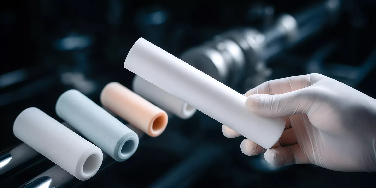
Cross-flow filtration introduces tangential velocity (2–4 m/s) that generates 20–60 Pa shear stress, continually removing foulants from the membrane wall. This dynamic reduces concentration polarization and maintains higher flux stability than dead-end operation, making Alumina Membrane Tubes for Wastewater Treatment ideal for continuous industrial processes.
Cross-flow typically sustains substantially higher usable flux than dead-end on oily feeds (cross-flow ≫ dead-end qualitatively). Treat any LMH/bar figures as illustrative process windows—not guaranteed flux; design flux depends on pore, oil loading, cross-flow velocity, and fouling—request it on RFQ. Despite higher pump energy, fewer cleaning cycles can still favor cross-flow on continuous oily streams.
Operational benefits:
- Continuous self-cleaning via shear.
- Reduced fouling layer resistance.
- Stable flux over extended runs.
Wall shear stress calculations for turbulent cross-flow membrane hydraulics
For water viscosity 1 cP and velocity gradient 8,000 s⁻¹, wall shear stress τ = μ(∂u/∂y) ≈ 80 Pa. This magnitude effectively prevents cake formation, keeping transmembrane pressure constant within 2–4 bar.
Concentration polarization theory and cake layer resistance modeling
Concentration at the membrane surface rises only 2–5× above bulk in cross-flow mode versus 50–200× in dead-end operation. Consequently, oil-cake permeability remains 50–500× greater, sustaining consistent flux.
Specific energy consumption analysis for different filtration configurations
Cross-flow systems consume 0.08–0.15 kWh/m³ permeate. Dead-end configurations require 0.12–0.25 kWh/m³ due to frequent backwashing, often with lower productivity per area when backwash frequency dominates.
Field Validation of Alumina Membrane Tubes for Wastewater Treatment in Petrochemical Applications
Published case context (for example SAGD-related membrane literature5) shows alumina MF tubes are often selected for high oil rejection on emulsified petrochemical feeds—rejection is feed-/pore-/TMP-dependent; state target oil in effluent on RFQ. Treat feed and permeate mg/L bands as example ranges—confirm on water analysis / pilot.
Membranes can resist H₂S, CO₂, and elevated TDS when the module, seals, and cleaning chemistry are rated for the duty. Flux decline and recovery are site-specific; do not treat hour-based run logs or recovery percentages as ADCERAX contractual SLA. Cost and lifespan comparisons versus polymer are application-dependent—request duty-matched economics on RFQ.
RFQ / pilot checks (not contractual guarantees):
- Target effluent oil & grease vs discharge limit (e.g., EPA Method 1664 context).
- Design flux, TMP, and expected cleaning interval for the oil type and temperature.
- High oil rejection goal stated as a water-analysis target—not a fixed % SLA.
Produced water chemistry challenges in SAGD petroleum recovery operations
Produced water contains heavy hydrocarbons, dissolved gases, and fine solids. Alumina’s chemical inertness and rigidity prevent structural degradation, enabling continuous performance under 60–80 °C operation.
Long-term flux decline monitoring and chemical cleaning effectiveness quantification
Flux typically declines between cleans and recovers after alkaline/ultrasonic CIP when the foulant and membrane rating match—request design flux and recovery expectations on RFQ rather than assuming fixed LMH or recovery percentages.
Compliance rate documentation and total cost of treatment analysis
Alumina systems are often specified to hold effluent oil and grease within the facility’s discharge limit when pore, TMP, and cleaning are matched to the feed. Cleaning cost and service-life advantages versus polymer are application-dependent—confirm on RFQ; not a contractual cost or lifespan SLA.

How Do NaOH and Ultrasonic Regeneration Protocols Restore Alumina Membrane Tubes for Wastewater Treatment?
Common alkaline + ultrasonic cleaning approaches (for example dilute NaOH in a warm CIP window with ultrasonic assist in the tens-of-kHz range) can restore permeability—validate on foulant and membrane rating. Saponification and cavitation help remove compacted organic fouling when chemistry and intensity stay within the module’s limits.
Combined chemical-ultrasonic CIP often outperforms chemistry alone on oily ceramics, but recovery is foulant- and duty-dependent. Set cleaning intervals from pilot data rather than fixed hour guarantees.
Performance improvements:
- Hydrolysis converts oils to soluble soaps.
- Cavitation pressure dislodges foulants.
- Controlled frequency minimizes material fatigue.
Saponification reaction kinetics for triglyceride oil removal from ceramic surfaces
NaOH hydrolyzes triglycerides into glycerol and sodium salts, enhancing solubility. Elevated temperature accelerates saponification; removal efficiency remains foulant-dependent—validate on the actual oil package.
Ultrasonic cavitation parameters optimized for membrane pore structure geometries
Ultrasonic assist in the tens-of-kHz range is a common deep-pore cleaning approach for ceramic MF; intensity and exposure must stay within the module rating—validate rather than assuming fixed bubble size or cavitation-pressure figures.
Cleaning frequency optimization balancing flux recovery versus membrane longevity
Clean often enough to avoid irreversible fouling, but avoid over-cleaning. Mechanical aging is duty- and chemistry-dependent—request strength/aging data if needed (ASTM C1161-style testing may be used for screening); do not treat aging percentages as a lifespan proof.
Industrial Wastewater Treatment Performance by Application
Example ranges only—confirm on water analysis / pilot. Flux and service life are illustrative process windows, not guaranteed SLA.
| Wastewater Source | Feed Oil Concentration (example) | Permeate Oil Quality (example target) | Illustrative Flux Window (L/m²·h) | Service Life (duty-dependent) |
|---|---|---|---|---|
| Metalworking emulsions | 2,000–8,000 mg/L | <5 mg/L (high rejection goal—RFQ) | illustrative; request design flux | confirm on RFQ |
| SAGD produced water | 1,500–3,500 mg/L | <10 mg/L (high rejection goal—RFQ) | illustrative; request design flux | confirm on RFQ |
| Refinery desalter effluent | 500–2,500 mg/L | <8 mg/L (high rejection goal—RFQ) | illustrative; request design flux | confirm on RFQ |
| Food processing (fryer oil) | 3,000–12,000 mg/L | <10 mg/L (high rejection goal—RFQ) | illustrative; request design flux | confirm on RFQ |
System Configuration Selection Matrix
| Design Condition | Recommended Configuration |
|---|---|
| Feed oil >5,000 mg/L or solids >500 mg/L | Two-stage: pre-filtration (50–100 µm) + ceramic membrane (0.1–0.2 µm) |
| Capacity >100 m³/day or footprint <20 m² | Multi-channel (7–19 channels) modules with high packing density |
| Feed temperature 10–40 °C (variable) | Variable frequency pumps with flux control (2.5–3.5 bar TMP) |
Conclusion
Alumina membrane tubes can deliver high oil rejection and durable service when pore size, TMP/flux, and cleaning match the oily emulsion—confirm targets on water analysis and RFQ rather than assuming fixed %/hour/month KPIs.
For an RFQ, include: pore-size band, oil type / emulsifier package, temperature, design TMP and flux, preferred cleaner chemistry, and any module drawing or channel geometry. Browse ceramic membrane options, custom services for drawing-based builds, and optionally alumina tubes for related tube forms—or start from the microporous alumina filter tube product page.
Related reading
- Microporous alumina filter tubes — material and efficiency context when the duty is industrial separation hardware rather than wastewater membrane RFQ.
- Alumina ceramic in petrochemical systems — broader alumina-part context in petrochemical process equipment.
- Alumina thermowell tubes in petrochemical crackers — same industrial domain for high-temperature sensing wells (not membrane filtration).
FAQ
1. How do alumina membrane tubes achieve stable performance under harsh chemical conditions?
Their crystalline α-alumina structure resists hydrolysis and swelling across common cleaning and process chemistries when the grade, binder, seals, and foulant are compatible—confirm cleaning chemistry and temperature limits on RFQ (module-/seal-limited).
2. What factors influence the total operating cost of membrane systems?
Key components include energy (0.08–0.15 kWh/m³), chemical cleaning ($0.05–0.12/m³), membrane amortization ($0.12–0.22/m³), and labor ($0.20–0.36/m³). Stable flux reduces both cleaning and energy demands.
3. Can alumina membranes be customized for specific wastewater compositions?
Yes. Available pore bands typically span the ceramic MF range (commonly discussed as about 0.1–5 µm—confirm on RFQ/drawing), with multi-channel geometries selected for flow rate and particle-size distribution on metalworking or petroleum streams.
4. How does alumina compare to polymeric membranes in lifecycle economics?
Alumina membrane tubes often outlast polymer on chemically aggressive oily duties and can reduce cleaning frequency when flux is stable—but lifespan months and cost savings are application-dependent. Request a duty-matched TCO comparison on RFQ; do not treat percentage cost cuts as contractual SLA.
References:
-
Learn about the critical role of droplet size distribution in treatment processes and its impact on overall efficiency. ↩
-
Understanding interfacial tension is crucial for grasping how emulsions are stabilized, making this resource invaluable. ↩
-
Exploring the DLVO theory will deepen your knowledge of emulsion stability mechanisms, essential for various applications. ↩
-
Exploring hydrophilicity will provide insights into how materials interact with water, crucial for applications in coatings and adhesives. ↩
-
Discover insights on SAGD operations and their effects on wastewater management, crucial for environmental sustainability. ↩