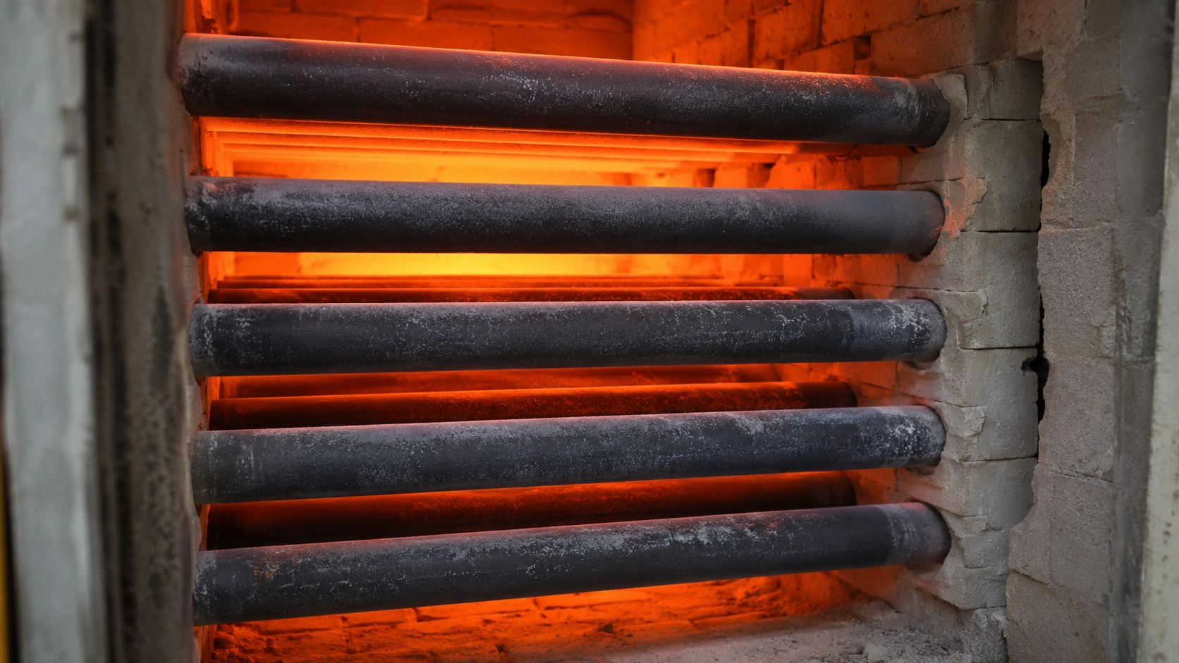
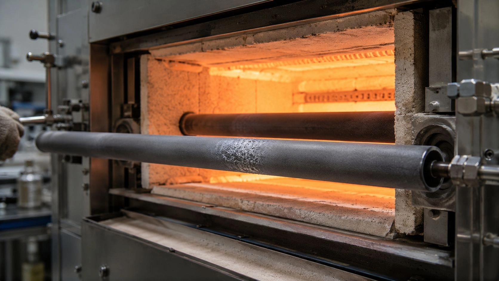
SiC radiant tubes are worth considering in galvanizing line furnaces when the heating section needs higher heat flux, stable indirect heating, and better resistance to oxidation, thermal cycling, or creep-related distortion than alloy tubes can provide. The strongest fit is a radiant-tube heating or soaking zone where atmosphere isolation, strip temperature uniformity, burner compatibility, and predictable tube geometry are more important than impact tolerance or lowest initial purchase cost.
The decision is not simply "ceramic is better than alloy." It is a question of whether the specific operating condition in the specific furnace zone justifies the properties SiC provides — and whether the failure being seen is actually a material problem rather than a burner, support, or atmosphere problem that a material switch alone will not fix.
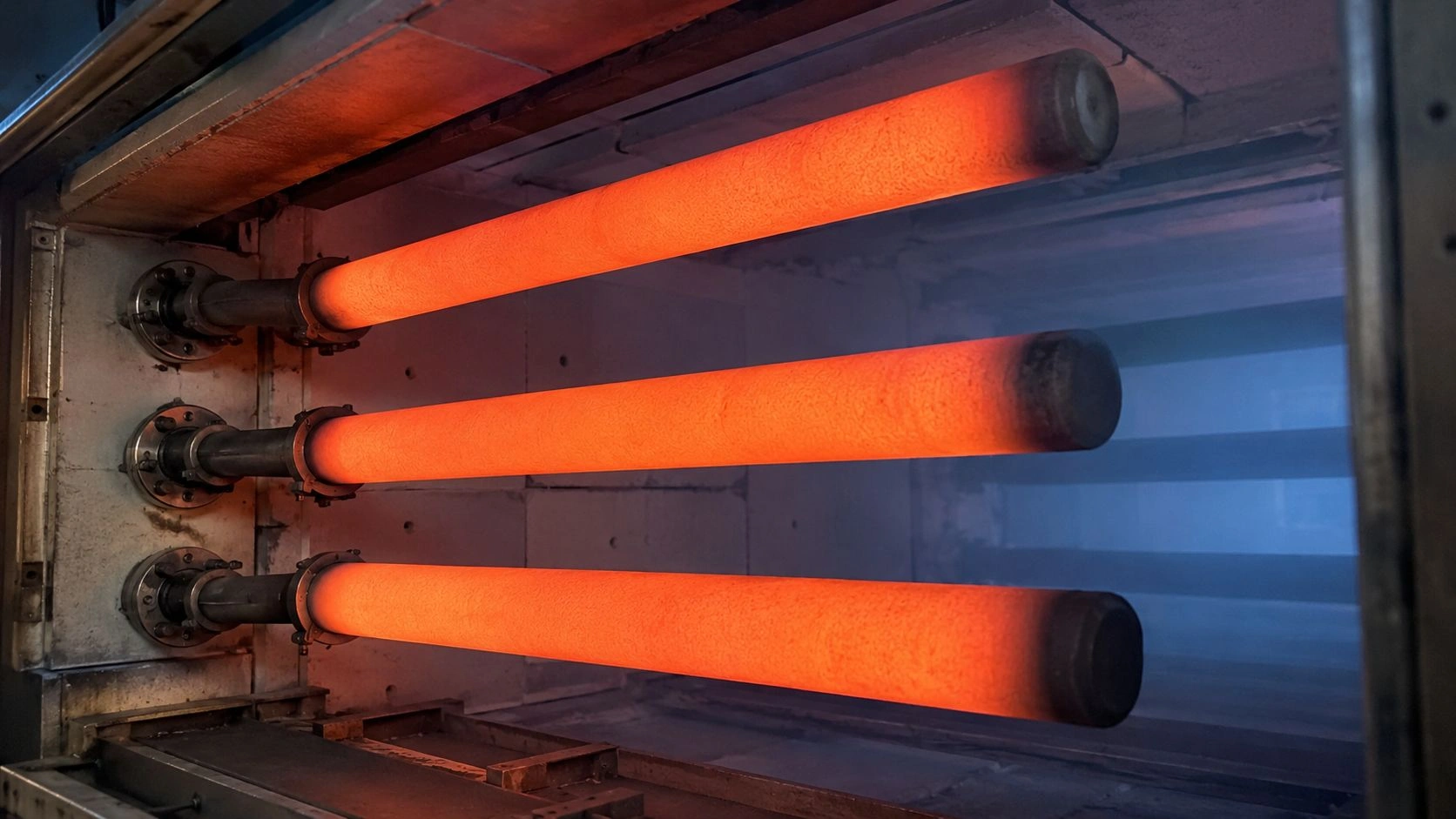
SiC radiant tubes in a CGL furnace radiant-tube heating section — providing indirect heat transfer, atmosphere separation, and geometry stability under repeated firing cycles.
Where SiC radiant tubes add value in a galvanizing line furnace
In a continuous galvanizing line, radiant tubes are used where the furnace must heat the strip indirectly while maintaining a protective atmosphere and avoiding direct flame contact with the steel surface. Published furnace instrumentation guidance explicitly states that ceramic radiant tubes are used in continuous annealing and galvanizing line heating furnaces to avoid oxygen contamination and flame-length hotspots — both of which can create surface defects on the strip or disrupt the thermal profile needed for proper metallurgical treatment.
That framing positions SiC's value as more than a high-temperature material claim. It is a system-level argument: the radiant tube simultaneously functions as a heat-transfer surface, combustion gas barrier, atmosphere protection component, and mechanically mounted ceramic structure. When one or more of those functions is stressed — by higher heat flux requirements, by frequent thermal cycling, or by the dimensional demands of a tight soaking temperature window — SiC's property combination becomes relevant to consider. Modern all-radiant-tube annealing furnaces, used in exposed automotive panel production, confirm that furnace radiant tube systems are central to achieving strip surface quality and mechanical property control, not peripheral thermal equipment.
Radiant-tube heating vs direct-fired furnace zones
SiC's strongest argument applies in radiant-tube heating and soaking sections, not in direct-fired furnace zones where flame-strip contact is part of the design intent. For DFF (direct-fired furnace) zones, which heat strip rapidly at lower furnace entry, the tube material question is not the same engineering problem as it is in the indirect-fired heating pass. Published CGL furnace descriptions commonly cite DFF strip-entry temperature bands in the open-literature range around 680–750°C; confirm against the line's measured profile and furnace OEM or supplier data — not as a contract temperature. The operational mode differs from indirect radiant-tube heating. The SiC selection question becomes most relevant after the strip enters the indirect radiant-tube heating zone.
Why atmosphere isolation matters for coated steel strip
A galvanizing line processes strip that will receive a zinc coating. The surface chemistry of that strip at the time of coating affects adhesion and uniformity. Oxygen contamination, combustion byproduct exposure, or uneven strip temperature from flame hotspots all create surface conditions that increase the risk of coating defects. The ceramic radiant tube is one of the architectural elements that prevents combustion gases from reaching the strip atmosphere — making tube integrity and geometry stability directly relevant to product quality, not only to tube service life.
What operating window makes SiC preferable to alloy radiant tubes
The following conditions, when present together, move SiC radiant tubes from a consideration to a strong candidate:
Published ceramic radiant tube documentation commonly cites heat-transfer capability near 50 kW/m² at about 1,050°C as an open-literature design band for ceramic radiant tubes — treat that as a published/common range to verify against line heat-flux measurements and the supplier data sheet, not as a supplier or plant guarantee. The same literature positions SiSiC radiant tubes for high-temperature industrial heating including galvanizing and annealing. That framing makes the operating window question more concrete:
| Decision variable | Positive acceptance condition | Why it matters | Evidence anchor |
|---|---|---|---|
| Furnace role | RTH / soaking / indirect-fired heating section | SiC value appears where atmosphere isolation and radiant transfer are both critical | Ceramic radiant tubes specifically used to avoid oxygen contamination and flame hotspots |
| Heat transfer demand | High radiant output required | SiC can support higher radiant heat-transfer design intent | Published/common range often cited near 50 kW/m² at ~1,050°C — verify with line data & supplier |
| Thermal cycling | Frequent burner on/off or strip-parameter changes | Cycling drives thermal gradients and potential creep deformation in CGL tubes | Published CGL research: cyclic loading from burner firing and process changes |
| Failure driver | Creep / oxidation / hot surface loading confirmed | Material upgrade may help only after system causes are separated | Published failure summary: overheating, hot spots, oxidation, carburization, and creep as failure mechanisms |
| Burner interface | Existing burner geometry can be adapted safely | Ceramic tube benefit depends on correct interface and mounting | Radiant tube burner configurations for galvanizing include single-ended, U, and W shapes |
Confirm against supplier data sheet and furnace design review.
If the answer to all five conditions is positive, SiC is on the shortlist. If mechanical impact, support contact, or burner chemistry is the primary driver, switching material alone is not the right first step.
Heat flux, tube temperature, and thermal cycling
The creep behavior of alloy radiant tubes under the repeated on/off firing cycles of a CGL furnace is one of the documented failure patterns in published radiant-tube research. Published CGL tube lifetime research shows that a tube experiences cyclic thermal loading from burner on/off firing and changing thermal surroundings, including neighboring tubes, furnace chamber conditions, and passing strip parameters. SiC's lower creep rate at high temperature and its higher thermal conductivity contribute to more stable tube geometry under that cycling pattern — which is why SiC enters the conversation when alloy creep or distortion is the documented limiting mechanism, not when tube failure cause is still undiagnosed.
Which failures are not solved by simply switching to SiC
Switching to SiC without diagnosing the root failure cause is one of the most common and expensive specification errors in galvanizing line furnace maintenance. The Failure Misdiagnosis Matrix below identifies the symptom patterns where a material change alone is unlikely to solve the problem:
| Symptom | Possible cause | Do not assume | Correct next check |
|---|---|---|---|
| Localized tube wall damage | Flame impingement / burner alignment | "Alloy material is weak" | Inspect burner flame pattern and tube inlet hot spot |
| Progressive sag / deformation | Creep under cyclic temperature gradients | "Only wall thickness matters" | Review burner on/off cycle, tube position, support layout |
| Inner-wall corrosion / perforation | Sulfur-bearing gas chemistry | "SiC automatically solves all atmosphere issues" | Analyze fuel gas and combustion byproducts |
| Repeated cracking near flange | Mechanical constraint / thermal expansion mismatch | "Higher-grade SiC fixes the design" | Recheck flange, seal, adapter, support stress |
| Coating defects downstream | Atmosphere / strip temperature / bath chemistry | "Radiant tube material caused all product defects" | Review dew point, oxygen, strip temperature, pot chemistry |
Failure classification based on published CGL radiant-tube lifetime research and galvanizing line failure analysis literature.
A published failure analysis of radiant tubes in a hot-dip galvanizing line attributed tube perforation to high-temperature sulphidation from sulfur-bearing gas chemistry — a failure mode where SiC does not provide a universal advantage and where root-cause analysis of fuel gas composition and combustion byproducts is the correct first response.
The most useful engineering rule for this application is: do not specify SiC until you know which failure you are solving. Published CGL radiant-tube research shows that overheating, burner hot spots, oxidation, carburization, and creep are all distinct failure mechanisms with different corrective actions — and substituting a ceramic material while the system cause is still active will not produce the expected service life improvement.
Material failure vs burner / support / atmosphere failure
SiC can address the material side of creep, oxidation, and high radiant output. It cannot correct a flame impinging on the tube wall, a flange that imposes mechanical constraint across thermal expansion, or process chemistry that has not been diagnosed. The correct sequence is diagnosis first, then material selection. An engineer who has confirmed that the tube is operating above the alloy creep limit under documented cycling conditions has a well-supported case for SiC. An engineer who sees tube failures without that diagnosis is at risk of repeating the same failure in a different material.
Why creep, sulphidation, and hot spots need separate diagnostics
These three failure modes each require different data to diagnose: creep requires knowledge of tube temperature history and firing cycle; sulphidation requires fuel gas composition and byproduct analysis; hot spots require burner flame length, alignment, and inlet temperature mapping. None of these is visible from the failed tube alone. Before requesting a SiC radiant tube proposal, collecting at least two of these data sets is a meaningful filter for whether the specification is ready.
How SiC radiant tubes should be specified for a CGL furnace
A CGL SiC radiant tube specification should begin with the furnace duty, not the material name. The silicon carbide ceramic material grades and properties — SiSiC, RBSiC, and NBSiC — differ in bonding phase, free silicon content, thermal conductivity, thermal shock behavior, shape capability, and corrosion boundary. Requesting "SiC radiant tube" without grade definition leaves the most important material variable unresolved. For radiant-duty tube forms and envelope options beyond this CGL furnace note, see the silicon carbide tube product overview.
For radiant tube service in CGL furnaces, the key specification inputs are furnace zone, burner type and output, tube geometry, mounting orientation, maximum tube surface temperature, firing duty cycle, atmosphere composition, dew point, and strip width range. Published radiant tube burner documentation describes configurations for coil annealing and galvanizing line applications across single-ended, U, and W tube shapes, with burner output commonly cited in the open-literature 30–300 kW range (confirm against the installed burner model and supplier rating — not a material guarantee). Recuperative system compatibility is part of that envelope. The SiC tube grade and wall geometry should be confirmed against that burner envelope.
The ceramic burner tubes at the radiant-tube burner interface require specific dimensional and material confirmation before replacement or new installation — the ceramic tube, flange adapter, and burner must be specified together rather than independently.
Grade, geometry, and burner compatibility
SiSiC provides high thermal conductivity and is commonly used in large radiant tube geometries; RBSiC supports complex large shapes depending on design and may offer different thermal cycling behavior; NBSiC (nitride-bonded SiC) introduces a different bonding phase with distinct behavior in some process atmospheres. Confirm with the supplier which grade is recommended for the documented tube temperature, cycling pattern, and atmosphere.
Required drawing and operating-condition inputs
Before a supplier can confirm that a specific SiC radiant tube grade is appropriate for a galvanizing line zone, they need the tube drawing (including inner and outer diameter, length, flange or adapter geometry, and closed or open end configuration), the burner model and fuel data, the maximum tube surface temperature at rated burner output, and the atmosphere specification including dew point and oxygen target.
What supplier data to request before approving SiC radiant tubes
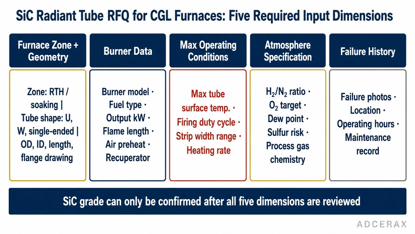
SiC radiant tube specification for CGL furnaces requires five operating-condition inputs confirmed before any material recommendation can be validated.
Before approving SiC radiant tubes for a galvanizing line furnace, request a supplier package and provide the following RFQ data:
| RFQ field | Required detail |
|---|---|
| Furnace zone | DFF transition, radiant-tube heating, soaking, or other |
| Tube geometry | Straight, single-ended, U, W, P / double-P, closed-end, open-end |
| Material grade | SiSiC, RBSiC, NBSiC, or supplier-recommended equivalent |
| Max condition | Tube surface temperature, furnace temperature, firing duty |
| Burner data | Burner model, fuel type, capacity, air preheat, flame length |
| Atmosphere | H₂/N₂ ratio, oxygen target, dew point, sulfur risk, process gas |
| Installation | Orientation, support method, flange / adapter drawing |
| Inspection | Dimensional tolerance, visual inspection, material certificate |
| Failure history | Photos, failure location, operating hours, maintenance record |
| Supplier deliverable | Drawing review, data sheet, installation guide, packaging plan |
RFQ field list for SiC radiant tube procurement in CGL furnace applications.
Ask the supplier to review the furnace drawing and operating history before recommending a grade. Failure photos, burner data, firing cycle, and atmosphere history are especially useful because they allow the supplier to confirm whether the tube geometry and material grade are matched to the actual duty rather than to a nominal operating condition that may differ from practice.
Evaluating SiC radiant tubes for a galvanizing line furnace? Send the tube drawing, burner model, furnace zone, failure notes, and atmosphere data for a grade-and-geometry checklist review against the radiant-tube duty; turnaround depends on inquiry complexity — no RFQ commitment required at this stage.
Frequently Asked Questions
Are SiC radiant tubes used in galvanizing line furnaces?
Yes. SiC and ceramic radiant tubes are used in CGL furnace zones that need indirect heating, atmosphere separation, and stable radiant heat transfer. Published furnace instrumentation guidance describes ceramic radiant tubes as the design choice for avoiding oxygen contamination and flame-length hotspots in continuous annealing and galvanizing line heating furnaces.
When should SiC be considered instead of alloy radiant tubes?
Consider SiC when high radiant output, thermal cycling frequency, oxidation resistance, and creep-related dimensional stability are the documented limiting factors in the current alloy tube service. Do not choose SiC only because a tube failed — first confirm whether the root cause is material creep, burner hot spot, support stress, sulfur chemistry, or thermal control. The material selection should follow the failure diagnosis, not replace it.
What is the main risk of using SiC radiant tubes?
The main risk is misapplication. SiC is strong at high temperature and resistant to creep and oxidation, but it is a ceramic material. Mechanical impact from installation, poor flange constraint across thermal expansion, or unsupported burner mismatch can create cracking or premature failure even when the ceramic material is otherwise appropriate for the temperature and atmosphere. The flange, adapter, and support system must be specified alongside the tube material.
Can SiC solve radiant tube creep in CGL furnaces?
It can help where alloy creep under cyclic temperature is the confirmed limiting mechanism. Published CGL radiant-tube research shows that tube deformation is strongly influenced by burner firing cycles, strip-parameter changes, neighboring tube radiation, and furnace chamber conditions — not by material alone. If the temperature history and cycling pattern are confirmed as the cause, SiC's lower creep rate is a genuine advantage. If the cause is still undiagnosed, the benefit is uncertain.
What information should be sent to a supplier before requesting SiC radiant tubes?
Send the tube drawing including flange and adapter geometry, the furnace zone identification, the burner model and fuel data, the maximum tube surface temperature at rated output, the atmosphere specification including dew point and oxygen target, failure photos and operating hours, and any restrictions on flange or mounting design. The more operating history is provided, the more accurately the supplier can confirm grade selection and geometry.
Are SiSiC, RBSiC, and NBSiC the same for radiant tube applications?
No. They differ in bonding phase, free silicon or nitride-bonded content, density, thermal conductivity, thermal shock behavior, shape capability, and corrosion boundary. SiSiC provides high thermal conductivity and is commonly used in larger radiant tube geometries. RBSiC supports complex large shapes and has different thermal cycling characteristics. NBSiC has a distinct bonding phase that affects its behavior in some process atmospheres and thermal cycling conditions. Treating "SiC" as a single grade leads to incorrect material selection — confirm the specific grade with the supplier against the confirmed operating duty.
Related reading
- SiC tube creep resistance at 1400°C under load — creep deep dive; this page stays on CGL radiant-tube duty and failure checks
- Active vs passive oxidation SiC failure modes — oxidation boundary; not the galvanizing RFQ checklist
- SSiC vs RBSiC vs SiSiC grade selection guide — cross-form grade gate; this page stays on CGL radiant duty, not total form selection