SiC tubes are suitable for coal gasification reactor internals when the component must resist high-temperature reducing gas, abrasive solids, thermal cycling, and selected coal-ash or slag exposure better than metals or oxide ceramics can in the same service position. They should not be specified by temperature rating alone. The decision must include syngas chemistry, steam content, H₂S and HCl levels, ash composition, slag basicity, dust load, flow velocity, pressure, tube wall thickness, support method, and SiC grade — because each of these variables can independently change whether SiC survives or fails in the specific gasifier zone.
That specification discipline — environment first, material choice second — is the engineering principle this guide is built around.
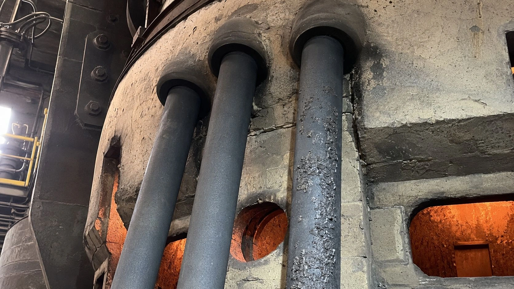
SiC tubes in coal gasification reactor internals face a combined environment of high-temperature reducing gas, steam, coal ash and slag, and abrasive solids — tube selection must start with gasifier chemistry, not with temperature rating alone.
This article is part of ADCERAX's coverage of silicon carbide tubes for high-temperature furnace, corrosive, and process applications, which includes SSiC, RBSiC, and NSiC grades for industrial protection tube, heat-exchange, and process-tube service.
When SiC tubes belong inside coal gasification reactors
SiC tubes belong in coal gasification reactor internals when the component must combine high-temperature stability, abrasion resistance, thermal shock resistance, and corrosion resistance in reducing or mixed gas environments — and when those requirements exceed what metals or oxide ceramics can sustain at the service position.
Gasification service is substantially more severe than a standard furnace tube application. NETL characterizes gasifier refractory service conditions as requiring materials to endure steam, hot coal slag, strongly reducing gas, elevated temperature, and pressure simultaneously. That combination disqualifies most conventional metal alloys at the temperature and atmosphere extremes of entrained-flow and slagging gasifiers, and it challenges the oxide ceramics that would otherwise be stable candidates in air-atmosphere furnaces.
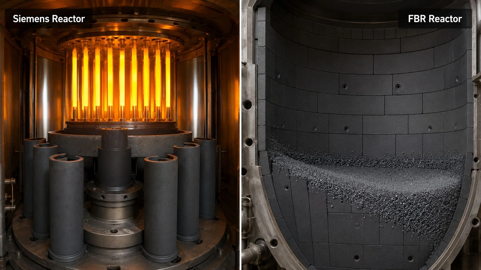
SiC as an internal tube, liner, protection tube, or flow insert. SiC tubes in gasifier service can take several forms: a thermocouple protection tube inside the gasifier vessel, a sampling tube for syngas or slag analysis, a liner sleeve protecting a metal nozzle or port, a flow-directing insert in a cyclone or char separator, or a heat-exchange tube in a high-temperature syngas cooler. Each application has a different primary failure mode and a different exposure severity.
Why gasification service is harsher than ordinary furnace service. An ordinary air-fired furnace tube operates in oxidizing air at a fixed temperature. A gasifier internal may operate in a gas that shifts from oxidizing to strongly reducing as the coal conversion proceeds, contains water vapor and HCl at elevated concentration, carries entrained char and ash particles at velocity, and contacts molten slag droplets in slagging gasifier zones. The oxygen partial pressure can be extremely low — orders of magnitude below equilibrium air — which changes the surface behavior of protective oxides that SiC normally forms.
Where metals and oxide ceramics reach their limits. High-temperature metal alloys used in syngas coolers and internal fittings are susceptible to corrosion from H₂S, HCl, and alkali deposits, and to creep at sustained high temperature. Alumina, while stable in air, can be attacked by basic slag and alkali vapors. High-chromia refractories used as gasifier vessel linings have different exposure conditions than a ceramic tube serving as a discrete internal component. SiC's combination of thermal conductivity, thermal shock resistance, chemical stability in reducing gas, and abrasion resistance makes it a meaningful candidate for positions where these metals and oxide ceramics fail earliest.
The gasifier variables that control SiC tube performance
SiC tube performance in gasifier internals is not controlled by temperature alone — it is controlled by the interaction of six environment variables that can individually change whether SiC survives in a specific zone.
[CITE: Published research on high-temperature corrosion of SiC ceramics by coal ash establishes that coal ash composition strongly affects refractory corrosion resistance, distinguishing acidic, alkaline, and nearly neutral ashes with different corrosion behavior, while NETL documentation on gasifier refractory service confirms that the relevant environment includes steam, hot coal slag, strongly reducing conditions, elevated temperature, and pressure simultaneously — establishing that SiC tube selection for coal gasification internals requires ash chemistry and syngas composition review rather than temperature rating alone.]
The SiC Tube Risk Matrix below maps key gasifier conditions to lower-risk and higher-risk interpretations:
| Variable | Lower-risk condition | Higher-risk condition | What to verify |
|---|---|---|---|
| Syngas chemistry | Stable reducing gas with known impurities | H₂S, HCl, steam, alkali vapor, variable oxygen potential | Full gas composition and dew point |
| Slag contact | No direct molten slag contact | Continuous slag film or slag droplet impingement | Ash/slag chemistry and viscosity |
| Ash chemistry | Known neutral or compatible ash | Basic, alkali-rich, iron-rich, or changing coal ash | Coal blend and slag basicity |
| Dust/solids flow | Low dust load, low velocity | High-velocity ash, char, slag particles | Flow velocity and particle load |
| Thermal cycle | Controlled startup/shutdown | Frequent cycling or quench events | Ramp/cooling profile |
| Tube function | Protective insert or replaceable liner | Load-bearing pressure boundary assumption | Mechanical role and support |
| SiC grade | Grade selected by chemistry and porosity | Generic "SiC" specification only | SSiC/RBSiC/NSiC/ReSiC route |
| Geometry | Smooth bore, supported length, accessible replacement | Long unsupported span, sharp ports, rigid seals | Drawing and support layout |
Values indicative; verify with supplier-specific SiC grade data, ash/slag testing, and application-specific exposure trials.
Reducing syngas: CO, H₂, H₂O, H₂S, HCl. In typical entrained-flow coal gasification, syngas contains CO and H₂ at high partial pressure with CO₂ and H₂O. The oxygen partial pressure is extremely low. SiC generally maintains good chemical stability under these conditions because the reducing environment suppresses the oxidative corrosion that would attack many oxide ceramics. However, H₂S and HCl at elevated concentration can attack certain SiC surface phases over extended exposure, and steam at high temperature can affect the protective SiO₂ surface layer that SiC normally maintains. Gas composition — not just "reducing atmosphere" — must be specified.
Coal ash and slag basicity. Published high-temperature corrosion literature distinguishes acidic, alkaline, and neutral ashes because slag basicity directly determines how aggressively the molten phase attacks a ceramic boundary. Basic ashes with high alkali and iron content can reduce slag viscosity, increase reactivity at the melt-ceramic interface, and produce more rapid wall loss than acidic or neutral ashes. SiC in contact with a basic slag behaves differently than SiC in a dry reducing gas stream — the slag chemistry is a separate and often more important variable than the gas atmosphere alone.
Erosion from char, ash, and dust flow. In gasifier zones with high particle velocity — cyclones, char separators, transport lines — abrasive wear from solid particles can be the dominant failure mechanism, not chemical corrosion. SiC's hardness and abrasion resistance are significant advantages over oxide ceramics and metals in these positions. The flow velocity, particle size, and angle of impingement determine whether erosion or corrosion dominates — and the tube wall thickness and support design must be matched to the erosion rate, not just the corrosion resistance.
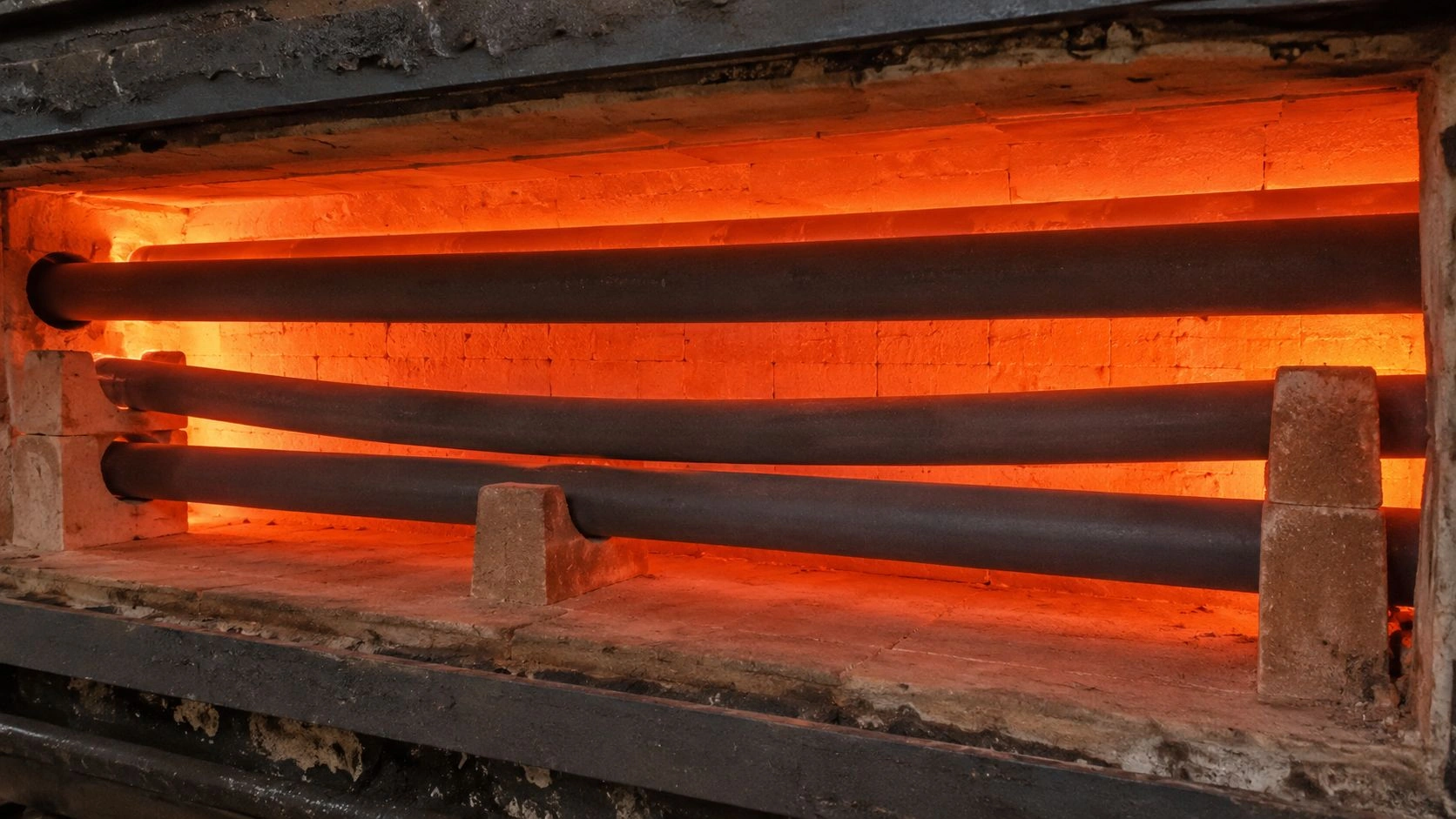
Temperature gradients, pressure, and cycling. High-temperature syngas cooler literature identifies corrosive raw-gas components and high dust loads as primary design challenges. Beyond chemistry, the mechanical demands of gasifier service include pressure differentials across tube walls, thermal gradients during startup and shutdown, and in some cases rapid thermal cycling during load changes or trips. SiC's thermal shock resistance is an advantage in these conditions, but support design and end-seal geometry must accommodate thermal expansion without introducing mechanical stress concentrations.
Do not misdiagnose slag chemistry, erosion, or support problems as SiC failure
A failed SiC tube inside a gasifier is not automatic proof that SiC was the wrong material. Before changing material grade or switching to a different ceramic family, the failure mechanism should be documented — because replacing the tube without identifying the root cause will reproduce the failure.
Chemical corrosion vs abrasive erosion. Wall thinning in a gasifier tube can look identical whether it comes from chemical dissolution into slag or from abrasive erosion by high-velocity particles. Chemical corrosion tends to be more uniform if the slag contact is uniform; erosion tends to show directionality correlated with flow path and impingement angle. A cross-section through the tube wall at the failure location — showing whether the surface is smooth or rough, whether there is a reaction layer or a clean sharp wear surface — helps distinguish the mechanisms.
Feedstock/ash change vs material batch problem. If the tube begins to fail after a change in coal supplier or blending ratio, the primary suspect is the ash chemistry change, not the tube grade. Basic or iron-rich ash from a different coal blend can significantly accelerate corrosion of a tube that has performed acceptably on the previous coal. Coal blend records and ash chemistry data should be cross-referenced against tube life data before any supplier or grade change is specified.
Support cracks vs thermal shock or point loading. Cracks near the tube support, end seal, or mechanical transition point are more likely caused by restraint of thermal expansion or point loading than by bulk material failure. A SiC tube that cannot expand freely during startup will generate axial stress at the constrained point — the crack location then identifies the mechanical design problem rather than the material limit.
Fouling and plugging vs tube material incompatibility. Research on slag behavior in gasifiers confirms that gasifier availability can be affected by slag buildup and downstream fouling. If a tube becomes blocked by slag or ash accumulation, the tube material is unlikely to be the cause — flow geometry, temperature profile at the tube surface, and upstream particle load are the relevant variables. Switching to a different SiC grade will not resolve a fouling problem that originates in process conditions.
The Failure Diagnosis Matrix below maps observed problems to better diagnostic questions:
| Observed problem | Common assumption | Better diagnostic question |
|---|---|---|
| Tube wall thinning | SiC grade too weak | Is ash erosion or high-velocity dust the dominant cause? |
| Local corrosion | Supplier quality issue | Did slag chemistry, basicity, or coal blend change? |
| Cracking near seal | SiC too brittle | Is thermal expansion restrained by the mounting design? |
| Surface deposits | SiC incompatible | Is slag viscosity or downstream fouling controlling deposits? |
| Internal blockage | Tube ID too small | Is particle load, condensation, or slag carryover increasing? |
| Uneven wear | Material inconsistency | Is flow impingement directional or support misaligned? |
| Unexpected gas leakage | Porous SiC grade issue | Was gas-tightness specified and tested? |
Diagnosis should be based on failure location, wall-loss pattern, deposit chemistry, and coal blend records before any material change is specified.
SiC grade and tube geometry for gasification internals
After confirming that the failure mode is a material-side problem that SiC can address, the grade and geometry must be specified against the specific gasifier environment — not from a catalog temperature rating.
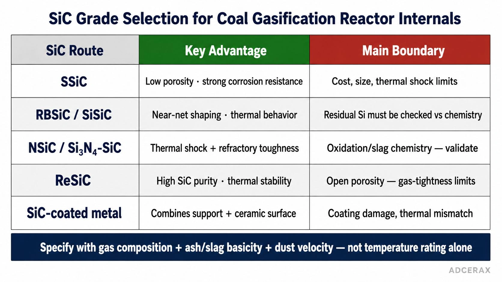
SiC tube grade selection for coal gasification internals requires matching density, porosity, and residual phase to the specific gasifier zone chemistry — not selecting by temperature rating alone.
The SiC Grade Boundary table below maps the main SiC routes to their gasifier-internal fit:
| SiC route | Potential fit | Key advantage | Main boundary |
|---|---|---|---|
| SSiC | Dense tubes, liners, protection sleeves | Low porosity and strong corrosion resistance | Cost, size, thermal shock, fabrication limits |
| RBSiC/SiSiC | Structural tubes and complex shapes | Near-net shaping and good thermal behavior | Residual silicon must be checked against chemistry |
| NSiC/Si₃N₄-SiC | Refractory-style internals and slag-facing components | Thermal shock and refractory toughness balance | Oxidation/slag chemistry must be validated |
| ReSiC | High-temperature structural hot-zone duty | High SiC purity and thermal stability | Open porosity and gas-tightness limitations |
| SiC-coated metal or composite | Transitional internals or protected hardware | Combines support with ceramic surface function | Coating damage, thermal mismatch, repairability |
SSiC for dense corrosion-resistant tubes. Sintered silicon carbide provides the lowest porosity and the strongest corrosion resistance of the common SiC grades. For a protection tube exposed to syngas and slag droplets, SSiC's dense microstructure limits the depth of chemical penetration and provides a more uniform resistance to both corrosion and erosion. The trade-off is fabrication complexity for large or complex geometries, and potentially higher susceptibility to thermal shock compared to coarser-grained grades.
NSiC/Si₃N₄-SiC for refractory-style internals. Research directly comparing SSiC and Si₃N₄-SiC refractories under coal slag at 1500°C confirms that the grade choice matters substantially for slag resistance — "SiC" cannot be specified without identifying the bonding phase. Si₃N₄-bonded SiC grades have a different thermal shock tolerance and a different slag-corrosion boundary than sintered SiC. For slag-facing components in slagging gasifiers, Si₃N₄-SiC grades developed specifically for coal gasification applications provide a better-characterized starting point than generic SSiC or RBSiC.
RBSiC/SiSiC: residual phase and chemistry boundary. Reaction-bonded SiC retains a residual silicon phase in the microstructure. In strongly reducing atmospheres with high H₂ content or in contact with certain slag chemistries, the residual silicon can be preferentially attacked, increasing porosity and accelerating corrosion. The residual Si content and its chemical boundary must be confirmed against the specific syngas composition and slag chemistry before RBSiC is specified for direct slag contact.
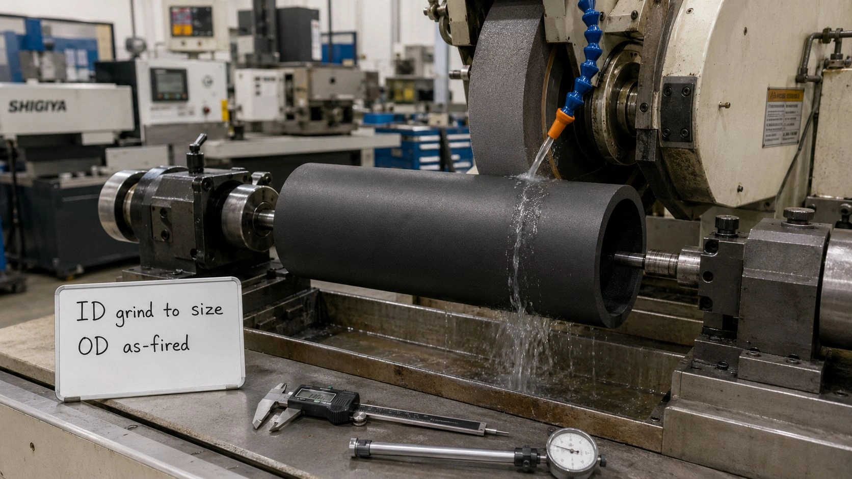
Tube geometry: wall thickness, closed end, liner clearance, ports, seals. For a protection tube in a gasifier access port, the tube geometry must accommodate the pressure differential, the flow direction, the thermal gradient through the wall, and the access mechanism for replacement. Excessive wall thickness increases thermal mass and may increase thermal shock risk during startup. Too-thin walls accelerate breakthrough if corrosion or erosion is active. Ports, holes, or notches in the tube create stress concentrations that must be accounted for in the support design.
The silicon carbide ceramic material grades — SSiC, RBSiC, and NBSiC — differ in density, porosity, and residual phase in ways that directly affect gasifier corrosion and erosion resistance. The metallurgical ceramics applications at ADCERAX include SiC components for abrasion, corrosion, and high-temperature process environments. For chemical process and corrosive-atmosphere applications, the petrochemical ceramics range provides additional context for SiC tube selection in corrosive gas environments.
The ceramic tube and pipe options across SiC, alumina, zirconia, and BN confirm that tube geometry, support method, and atmosphere compatibility must all be confirmed before final material selection.
RFQ checklist for SiC tubes in coal gasification reactor internals
A complete RFQ for SiC tubes in gasifier service must provide the environment chemistry and tube function context that allows a supplier to confirm grade suitability and recommend testing.
[CITE: Engineering guidance on SiC tube specification for coal gasification reactor internals confirms the complete RFQ sequence: gasifier type and reactor zone, syngas composition including CO/H₂/H₂O/CO₂/H₂S/HCl with oxygen potential, coal ash analysis and slag basicity, dust and char particle load with flow velocity, operating and peak temperature with pressure and dwell time, thermal cycling profile, tube drawing with OD/ID/wall/length/ports/closed-end design, seal and support method, and current failure history — because syngas chemistry and ash/slag chemistry together determine which SiC grade is appropriate, and a supplier who receives only "SiC tube for gasifier" cannot confirm corrosion resistance, gas-tightness, or grade suitability without the remaining environmental context.]
| RFQ field | Why it matters | Recommended wording |
|---|---|---|
| Gasifier type/zone | Defines temperature and exposure | "Entrained-flow/slagging/fluidized-bed/syngas cooler zone" |
| Gas chemistry | Controls corrosion route | "Provide CO, H₂, H₂O, CO₂, H₂S, HCl, alkali vapor if known" |
| Coal ash/slag chemistry | Controls slag corrosion | "Provide ash analysis, slag basicity, and slag contact condition" |
| Flow velocity and solids | Controls erosion | "State dust load, char/ash particle exposure, and velocity" |
| Temperature/pressure | Defines service boundary | "Continuous, peak, pressure, and dwell time" |
| Thermal cycling | Controls shock and cracking | "Startup/shutdown cycle and ramp/cooling profile" |
| Tube geometry | Controls stress and fouling | "OD, ID, length, wall, closed/open end, ports, bends" |
| SiC grade | Prevents generic material mismatch | "Quote SSiC/RBSiC/NSiC/ReSiC with density and porosity" |
| Validation | Confirms real environment fit | "Recommend ash/slag exposure and erosion test before batch order" |
RFQ fields are the minimum for a gasifier internal tube inquiry; add seal design, replacement access method, and liner clearance as needed.
For critical positions — direct slag contact, high-velocity particle zones, or applications where tube failure causes extended downtime — a coal-ash or slag exposure test using the actual coal or synthetic slag composition at the operating temperature is the most reliable pre-qualification method before ordering production quantities.
Evaluating SiC tubes for coal gasification reactor internals? Share your gasifier type and zone, syngas composition, coal ash analysis, slag basicity, flow velocity, operating temperature and pressure, tube geometry drawing, and current failure mode. ADCERAX engineers review whether SSiC, NSiC, RBSiC, or another ceramic tube route fits the application; turnaround depends on inquiry complexity — no RFQ commitment required at this stage.
Frequently Asked Questions
Can SiC tubes be used inside coal gasification reactors?
Yes, but only after environment-specific review. SiC tubes are strong candidates when high-temperature stability, abrasion resistance, thermal shock resistance, and selected corrosion resistance are required in the gasifier zone. Performance depends on syngas chemistry, ash and slag chemistry, dust load, pressure, and SiC grade — not on temperature rating alone.
Is silicon carbide resistant to coal slag?
SiC can be promising in reducing gasifier atmospheres, but coal ash and slag chemistry strongly affect corrosion resistance. Published research identifies ash basicity as a major controlling variable — acidic, basic, and neutral ashes produce different corrosion rates. Basic, alkali-rich, or iron-rich ashes can be particularly aggressive in some SiC grade and temperature combinations.
What gas species matter most for SiC gasifier internals?
CO, H₂, H₂O, CO₂, H₂S, HCl, alkali vapor, and oxygen partial pressure all matter. High-temperature syngas cooler literature identifies H₂S, HCl, H₂, and high dust loads as important harsh-environment design factors that affect tube material selection beyond what temperature rating captures.
Which SiC grade is best for gasifier tubes?
There is no universal grade. SSiC, RBSiC/SiSiC, NSiC, Si₃N₄-SiC, and ReSiC should be compared by density, porosity, residual phase, slag resistance, thermal shock tolerance, fabricability for the required geometry, and gas-tightness requirement. Published research comparing SSiC and Si₃N₄-SiC under coal slag at 1500°C confirms that grade matters — not just "SiC."
Why do SiC tubes fail in gasifier internals?
Common causes include slag corrosion, ash erosion at high velocity, thermal shock during startup/shutdown, support restraint cracking, atmospheric chemistry changes from coal blend variation, downstream fouling, or wrong SiC grade for the slag chemistry. Failure location and deposit chemistry should be documented before changing material or grade.
What information should I send to a supplier?
Send gasifier type and zone, syngas composition with H₂S and HCl levels if available, coal ash analysis with basicity, slag contact condition, dust load and flow velocity estimate, operating and peak temperature with pressure, thermal cycling profile, tube geometry drawing with OD/ID/wall/ports/end design, support and seal method, and failure photographs or description from current service.