Abrasive, adhesive and erosive wear all remove material, enlarge clearances and damage working surfaces, but their load paths differ. Abrasion involves hard particles or asperities pressed against a surface and moving along it. Adhesive wear starts with local bonding between sliding solids, followed by junction shear and material transfer. Erosion involves repeated particle or droplet impacts.
Particles alone do not identify the mechanism. A trapped grain can abrade a sleeve; the same grain carried by fluid can erode an elbow. Real equipment often experiences both, so material selection must begin with motion, loading and exposure.
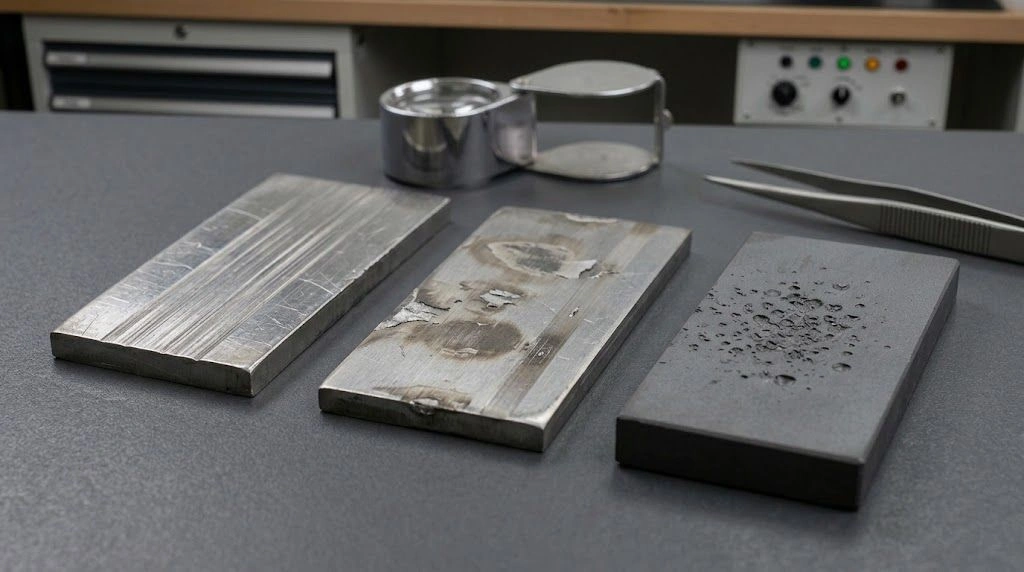
Illustrative wear textures support comparison; appearance alone cannot establish the failure mechanism.
What Are Abrasive, Adhesive and Erosive Wear?
These terms describe how contact removes or displaces material. They are not interchangeable labels for a rough surface, and they do not exhaust every possible wear mechanism.
Abrasive wear: hard features moving under contact load
Abrasion occurs when a harder particle or surface feature penetrates and moves along another surface. Depending on the materials, removal can involve microcutting, ploughing, grain pullout or brittle microfracture.
In two-body abrasion, the damaging feature is attached to the opposing surface, such as an asperity or firmly embedded particle. In three-body abrasion, loose particles occupy the interface. They can roll, slide, become embedded or fracture, so the contact may change during operation.
Directional scratches, grooves and displaced ridges support an abrasion hypothesis. Ceramics may instead show grain-scale removal and microchipping around the track.
Adhesive wear: junction formation and shear
Real contact occurs at microscopic surface peaks. Local junctions form as solids slide under load; continued movement breaks those junctions. If failure occurs within either material, fragments can transfer to the counterface or become debris.
This mechanism explains why both mating surfaces matter. A deposit on one part may be material removed from the other. STLE’s introductory explanation distinguishes this local transfer process from penetration and ploughing by a harder body. STLE: Tribology Wear
Smearing, torn regions, scuffing and galling are useful clues. A transfer layer alone, however, does not establish severe ongoing wear: its composition, stability and effect on the contact also matter.
Erosive wear: repeated impacts
Solid-particle erosion occurs when moving particles repeatedly strike a surface, commonly after transport by gas or liquid. Liquid-droplet impacts can also cause erosion. Repeated impacts produce cutting, indentation, fatigue or fracture depending on the target and exposure.
Important variables include velocity, impact angle, particle size, angularity, concentration and carrier fluid. Shallow impacts emphasize tangential action; steeper impacts increase the normal component. The angle producing maximum loss depends on the material and conditions, so there is no universal optimum or worst-case angle.
Localized thinning at elbows, restrictions and jet-impact zones is consistent with erosion, but requires confirmation against the flow path.
What Are the Key Differences in Real Equipment?
The practical distinction is how force reaches the surface. Abrasion involves loaded contact moving along it; adhesion involves junctions between sliding solids; erosion involves incoming impacts.
| Diagnostic factor | Abrasive wear | Adhesive wear | Erosive wear |
|---|---|---|---|
| Dominant action | Cutting or ploughing | Junction shear and transfer | Repeated impact |
| Contact | Hard feature or trapped particle against surface | Two sliding solids | Incoming particle or droplet |
| Particle role | Carries contact load | May be generated by junction failure | Delivers impact momentum |
| Key variables | Hardness ratio, shape, load, sliding distance | Material pair, lubrication, pressure, speed, temperature | Velocity, angle, size, concentration, fluid |
| Typical evidence | Grooves, scratches, embedded debris | Transfer patches, smearing, galling | Impact scars, craters, localized thinning |
| Common locations | Guides, sleeves, contaminated seals | Sliding shafts, seals, valve stems | Elbows, impellers, nozzles, leading edges |
| First mitigation question | Can penetration or particle entry be reduced? | Can surfaces be separated or the pair improved? | Can impact intensity or trajectory be changed? |
Start an investigation with five questions:
- Which surfaces actually touch, and under what load?
- Does material transfer appear on the opposing surface?
- Are particles trapped in a clearance or arriving from the flow?
- Does the damage align with sliding direction or an impact zone?
- Did lubrication, filtration, flow or alignment change before failure?
A sand grain in a loaded shaft–sleeve clearance may cause three-body abrasion. A suspended grain striking a bend may cause erosion. A transferred metal fragment can subsequently become an abrasive. Particle chemistry identifies what is present; trajectory and confinement explain how it causes damage.
Mitigation should follow that diagnosis. Better filtration may protect a sliding interface but leave upstream jet impingement unchanged. A new material pair may reduce adhesive transfer without preventing hard particles from scratching both surfaces.
Why Are Wear Mechanisms Often Misdiagnosed?
A wear scar records the final condition, not the entire sequence. Secondary damage can hide the initiating event, and aggressive cleaning can remove useful deposits.
Grooves do not always identify the first mechanism
Adhesive fragments, broken coatings and corrosion products can become third-body abrasives. A component recovered with long scratches may therefore have started failing through adhesion, coating fracture or corrosion.
Inspect the counterface and retain debris before deciding that harder material alone will solve the problem.
Friction and wear are different responses
A high friction coefficient does not prove adhesive wear or predict material loss directly. Surface films, lubrication and debris may alter friction while wear follows a different trend. A stable transfer film may change friction without causing the same damage as unstable tearing.
Measure wear separately, including the mating component. Preserving a ceramic sleeve while rapidly consuming its metal shaft is not necessarily an improved assembly.
Erosion, cavitation and corrosion need separate checks
Cavitation erosion results from vapor-bubble formation and collapse in a liquid, not solid particles striking the wall. Pump and valve pitting may involve either mechanism or both.
Erosion-corrosion involves interaction between mechanical damage and chemical attack. Removal of protective films can expose reactive material, while corrosion can weaken the surface subsequently removed by flow. Neither process is captured adequately by naming the fluid “slurry.”
| Equipment | Initial wear hypothesis | Additional mechanism to investigate |
|---|---|---|
| Slurry-pump sleeve | Trapped-particle abrasion | Corrosion or rubbing after clearance changes |
| Pipe elbow | Particle erosion | Erosion-corrosion |
| Mechanical seal | Adhesive or abrasive sliding | Thermal cracking and corrosion |
| Throttling valve seat | Contact wear | Jet erosion or cavitation |
| Contaminated bearing | Abrasion | Adhesion after lubricant-film breakdown |
| Ceramic guide | Abrasion | Edge fracture from misalignment |
These are investigation starting points, not diagnoses for every example.
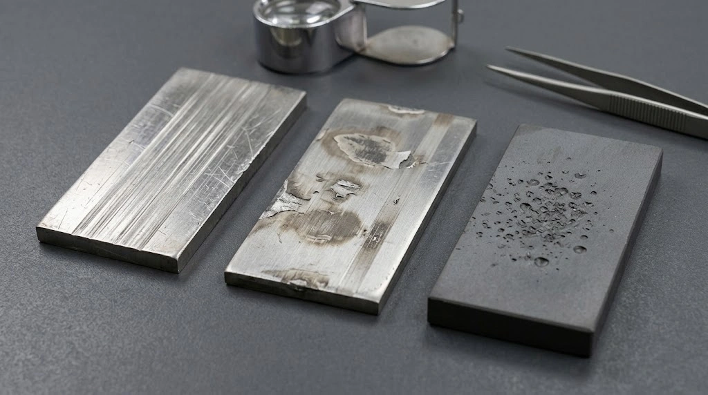
Different locations in one assembly may experience loaded sliding, material transfer and particle impact.
How Should Wear Be Inspected and Tested?
First preserve the failed part, its orientation and its operating history. Then choose a test that addresses the suspected contact system.
Photograph the complete component before cleaning. Record flow direction, sliding direction, installed orientation and the damaged zone. Photograph the mating part and retain loose debris separately. Record abnormal starts, dry running, pressure excursions and changes in solids or chemistry.
Next map dimensional loss. Useful measurements include wall thickness, bore growth, track depth, roundness, clearance and nozzle opening. A precision seal may fail through leakage long before total mass loss appears large.
For comparisons across materials, mass loss alone can mislead because density differs. Volume loss can be estimated as mass loss divided by density when the measurement genuinely represents removed material. Deposits, oxidation and retained fluid can invalidate that simple conversion.
Examine scars and debris with suitable magnification. Look for embedded grains, transferred layers, microcracks, pullout and impact features. Chemical analysis may help identify transferred material, but elemental identity alone does not reconstruct the full failure sequence.
Match the test to the engineering question
| Question | Representative ASTM method | Main boundary |
|---|---|---|
| Dry sand abrasion | G65, dry sand/rubber wheel | Does not reproduce every wet or confined contact |
| Slurry abrasivity or abrasion response | G75 | Defined slurry test, not a complete pump simulation |
| Wet sand abrasion | G105 | Wet wheel contact differs from free particle impact |
| Sliding material-pair behavior | G77, block-on-ring | Depends on the pair and selected conditions |
| Pin/ball-on-disk sliding | G99 | Coupon contact may differ from the component |
| Reciprocating sliding | G133 | Stroke and contact geometry matter |
| Gas-borne particle erosion | G76 | Not automatically representative of slurry or cavitation |
| Elevated-temperature particle erosion | G211 | Controlled hot-particle exposure |
| Cavitation | G32 or G134 | Different loading from solid-particle erosion |
These are distinct test families in the ASTM wear and erosion directory. Use the applicable edition and full procedure when specifying work.
A sliding test is not a pure adhesive-wear test: abrasion, tribochemical effects and other mechanisms may develop in its contact. Examine the resulting scars as well as the reported number.
ASTM G77 ranks material pairs under specified sliding conditions and reports loss for both bodies. Its public scope notes that the cited interlaboratory testing was limited to metals; ceramic application requires appropriate specimen preparation and interpretation. ASTM G77
ASTM G76 evaluates gas-entrained particle impingement. Its public scope cautions that laboratory results need correlation with actual service because particle size, velocity, angle and environment vary. A good gas-jet ranking is not a guaranteed slurry-service ranking. ASTM G76
Report abrasive composition and size distribution, material pair, load, speed, distance, fluid, temperature, finish and alignment. For erosion, also report impact angle, particle velocity and feed rate. Record replication and scatter; a small ranking difference may not be meaningful relative to variability.
Copyable wear-investigation record
| Part ID/location | Suspected modes | Contact pair | Motion/flow | Load/pressure | Particle material/size | Velocity/angle | Medium/temperature | Observed damage | Dimensional loss | Evidence retained |
|---|---|---|---|---|---|---|---|---|---|---|
Expert Insight: Test the Mechanism That Limits the Assembly
“Wear-resistant” is incomplete unless the test conditions and functional failure criterion are known. A liner, seal and nozzle may all lose material, yet their useful lives can be limited by different changes: remaining wall thickness, leakage clearance or spray geometry.
Select the measurement that captures that limit, then investigate the mechanism responsible. If a seal fails because its mating ring scores, measuring only the ceramic ring misses the assembly problem. If a nozzle chips during occasional particle surges, steady fine-particle testing may overlook the critical event.
Preserve startup, shutdown and upset conditions in the review. They can introduce dry contact, thermal gradients or impacts absent from normal operation. A material that performs well during steady duty may fail during these transitions.
The strongest comparison combines controlled coupon testing with representative component trials. Keep geometry, support, counterface and operating conditions documented so that improved results can be attributed to a defined change.
How Should Material and Ceramic Wear Parts Be Selected?
Begin with the dominant mechanism, then identify risks that could overturn the initial choice. Hardness helps resist penetration; toughness, grain retention, chemistry and component support determine whether that benefit survives actual loading.
For abrasion, assess hardness relative to the abrasive, microstructure, porosity and surface finish. For adhesive sliding, assess both materials, lubricant availability, pressure, temperature and alignment. For erosion, assess particle velocity and impact angle alongside fracture response and corrosion.
Ceramic screening directions
| Candidate | Reason to investigate it | Important qualification check |
|---|---|---|
| Alumina | Hard ceramic for many abrasion duties | Impact, edge support, grade and chemistry |
| ZTA | Potential improvement in chipping resistance over an alumina baseline | Composition, finish and actual loading |
| Zirconia | Tough ceramic for precision contact-loaded parts | Thermal conditions, stability and counterface wear |
| Silicon carbide | Abrasion/erosion with compatible chemical exposure | Grade, secondary phases, impact and mounting |
| Silicon nitride | Mechanical contacts involving impact or thermal cycling | Contact stress, finish, chemistry and geometry |
These are screening directions, not a universal ranking. Metals, carbides or polymers may remain appropriate where compliance, impact tolerance or another system requirement dominates.
A ceramic counterface can change a metal-to-metal adhesive contact, but it may abrade the mating metal or chip under concentrated loading. Test the pair. Likewise, reducing impact velocity or improving a flow transition may deliver more benefit than changing material while retaining the same damaging geometry.
For drawing-based sleeves, liners, seals, nozzles and other wear components, review custom ceramic components using the actual contact pair, particle conditions, medium, temperature, geometry, tolerances and inspection requirements.
Build the RFQ around service conditions
Include the current material, elapsed service, failure location and measured wear. Specify contact load separately from process-fluid pressure; they are not automatically equivalent. Supply particle-size distribution rather than a single nominal size where possible.
Provide working and peak temperature, chemical species, concentration, pH, lubrication, starts and stops, and possible cavitation. Attach geometry, mounting details, critical edges, tolerances, surface-finish requirements and the mating-part specification.
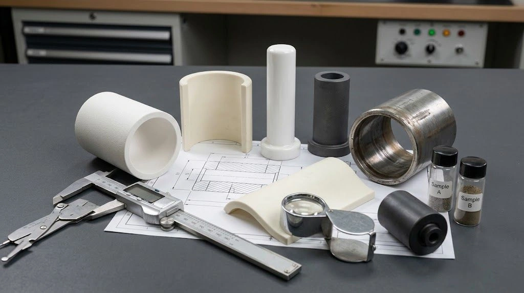
An actionable RFQ connects the worn component and process evidence to geometry and inspection requirements.
Copyable RFQ
Subject: RFQ — Custom Ceramic Wear Component
Component and application:
Current material/grade:
Service duration and functional failure criterion:
Failure location and measured dimensional loss:
Suspected primary/secondary wear mechanisms:
Gradual wear or sudden damage:
Contact and movement:
- Mating material and finish:
- Sliding / rolling / reciprocating / impact:
- Contact load or pressure:
- Speed, stroke and duty cycle:
- Lubrication, flushing and filtration:
- Alignment, clearance and mounting:
Particles and flow:
- Particle composition and hardness, if known:
- Size distribution and shape:
- Solids concentration:
- Carrier fluid or gas:
- Flow velocity:
- Impact angle or flow direction:
Environment:
- Chemical species, concentration and pH:
- Working and peak temperature:
- Thermal cycling:
- Corrosion/cavitation evidence:
- Startup, shutdown and upset conditions:
Part requirements:
- Preferred material, if any:
- OD / ID / length / wall:
- Critical edges and mating surfaces:
- Tolerances and Ra/Rz requirements:
- Inspection and acceptance criteria:
- Trial and repeat quantities:
Attachments:
Drawing / STEP file / worn-part photos / old part /
particle data / wear measurements / process diagram
Frequently Asked Questions
Can the same particle cause abrasion and erosion?
Yes. It may strike a flow passage, then become trapped in a loaded sliding clearance. Its load path changes the mechanism.
Do grooves prove abrasive wear?
They support that hypothesis, but debris from adhesion, coatings or corrosion may produce secondary grooves. Examine the counterface and history.
Are ceramics immune to adhesive wear?
No. Sliding ceramics can experience transfer, junction-related damage and tribochemical effects. Replacing one material does not eliminate contact-system risks.
Does greater hardness guarantee longer life?
No. Brittle chipping, impact, corrosion, poor support or counterface damage may dominate even when penetration resistance improves.
Can G65 and G76 results be compared directly?
No. They represent different contacts. Compare materials within a relevant, controlled test and validate the connection to service.
Conclusion
Abrasive, adhesive and erosive wear differ mainly in how load reaches the surface: loaded cutting or ploughing, sliding-junction failure, or repeated impact. Real failures can combine these processes.
Preserve both contact surfaces, map motion and flow, examine debris and measure functional geometry loss. Send that evidence with the drawing and service conditions to ADCERAX for ceramic-component review. Predicting service life requires representative testing or validated field evidence.