Tube furnace end seals must stay cool because their O-rings, lubricants, valves and feedthroughs usually have much lower temperature limits than the ceramic work tube. Excessive heat can degrade sealing behavior, increase vacuum gas load and change the forces applied to the tube.
“Cool” means within the approved operating range of the complete sealing assembly. It does not mean room temperature or as cold as possible.
Extended tube ends, insulation, radiation shields and appropriate cooling manage heat reaching the seals. The furnace setpoint alone cannot establish the temperature at an O-ring.
What Does a Tube Furnace End Seal Do?
An end seal connects the work tube to the external gas or vacuum system while closing the leakage path around the tube. Depending on the arrangement, it may retain a process atmosphere, limit air ingress, provide a pumping connection or carry a probe feedthrough.
A typical assembly includes a metal flange, an elastomeric O-ring, a gland that locates the ring, and a compression or clamping mechanism. Gas ports, gauges, cooling passages and internal shield supports may be added.
The metal body does not determine the assembly's temperature capability by itself. A lubricant, hose, connector or valve can impose a lower limit than the flange.
The seal belongs in the cold-end region
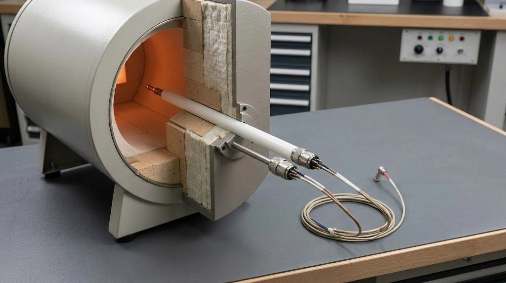
A work tube has several distinct axial regions: the heated length, the uniform-temperature process zone within it, the furnace-edge transition and the projecting ends. The sealing contact sits at a specified location on a projecting end.
The sample's required uniform-temperature length is therefore different from the tube's overall length. A tube long enough to hold the sample may still be too short for the sealing system.
Carbolite's accessory guidance specifies extended work tubes for its end seals and combines them with insulation plugs or radiation shields. This is a system arrangement, not a universal dimension applicable to every furnace. Carbolite work-tube accessories
Different assemblies have different limitations
| Configuration | Function | Point requiring review |
|---|---|---|
| Gas end cap | Controlled gas entry or exit | Seal chemistry and permitted pressure differential |
| O-ring vacuum flange | Removable vacuum connection | Gland fit, heat exposure and gas load |
| Double-O-ring flange | Two sealing contacts | Function of the intermediate space and temperature of both rings |
| Water-cooled flange | Heat removal near the seal | Cooling performance and failure response |
| Metal-gasket assembly | Specialized sealing duty | Joint design, required load and ceramic interface |
Two O-rings do not automatically provide intermediate pumping or cooling; the flange must be designed for that function. Similarly, a metal gasket is not a direct substitute for an elastomer in an existing gland.

Tube projection separates the end seals from the heated enclosure; actual seal temperature still requires verification.
Why Must the End Seals Stay Cool?
Preserve elastic sealing contact
An O-ring must conform to its mating surfaces and maintain sufficient contact as the joint changes during operation. Heat exposure can alter stiffness, dimensions and elastic recovery. Chemical exposure can compound those effects.
Compression set means that a compressed ring does not fully recover its original shape after the load is removed. The ring can remain in place yet have less ability to follow joint movement. A flattened ring is therefore relevant evidence, although compression set alone does not predict the exact leakage rate or remaining life.
Hardening, cracking, swelling and softening require investigation. They may reflect heat, incompatible process species, cleaning chemicals, lubricant or combined exposure. Replacing the ring without checking the cause can reproduce the failure.
Distinguish a hot leak from increased outgassing
A furnace that reaches its expected pressure when cold may perform differently during a long hot cycle. Thermal expansion can change gland clearance and alignment; an aged seal may not accommodate that movement.
Heating can also release gas from seals, grease, moisture or deposits inside the assembly. That increases pressure without requiring a new opening to the room.
Agilent's vacuum guidance distinguishes real leaks, outgassing, permeation and trapped-volume effects. Consequently, a pressure rise alone is not proof that an O-ring is leaking. Temperature records and an appropriate diagnostic test are needed. Agilent vacuum troubleshooting guidance
Compare pump-down behavior, seal-area temperature and process timing. Include changes in the sample, pump performance and connecting-line conductance before assigning the entire pressure rise to the flange.
Maintain atmosphere control
Under vacuum, a leakage path can admit air and moisture. In flowing-gas service, the direction and amount of leakage depend on local pressure conditions.
Consequences can include sample oxidation, altered reducing conditions, contamination and poor repeatability. Reactive or flammable-gas processes also depend on the designed containment and safety controls.
A nominal gas-flow setting cannot demonstrate atmosphere purity when the sealing boundary has changed. Investigate both the seal condition and the measured process atmosphere.
Limit joint movement and ceramic loading
The tube, flange, bolts, O-ring and support frame expand differently. Heating can alter compression and alignment, with the direction of the change depending on the joint geometry.
If a rigid connection prevents necessary movement, thermal expansion can transfer load into the brittle ceramic. Tightening a hot leaking flange may add radial or bending stress without addressing the underlying problem.
Connected hoses, valves and gauges must also remain within their approved limits. Exposed metal may become a burn hazard even though it is outside the furnace enclosure.
| Change | Possible consequence |
|---|---|
| Reduced seal recovery | Leakage as the joint moves |
| Hardening or cracking | Poor conformance and leakage paths |
| Softening with unfavorable clearance | Distortion or extrusion |
| Increased gas release | Slower pump-down or higher operating pressure |
| Differential expansion | Changed compression or alignment |
| Hot attached hose or feedthrough | Degradation elsewhere in the assembly |
| Restrained ceramic movement | Chipping, bending stress or fracture |
How Does Heat Reach the End Seals?
Conduction through the tube and fixtures
Heat travels through the solid tube toward its projecting ends. Material conductivity, wall cross-section, temperature gradient and available heat rejection all matter.
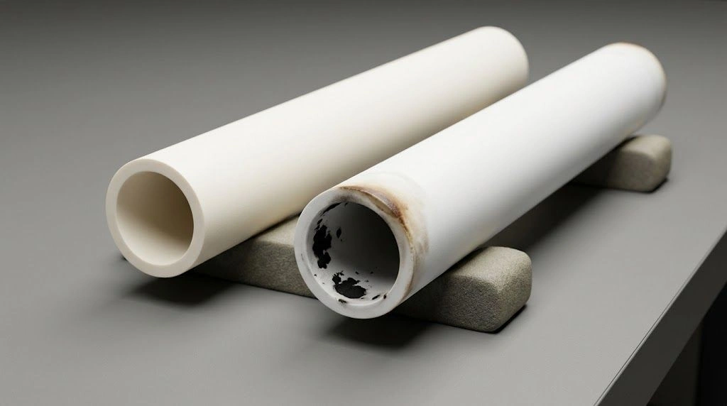
A thicker wall or a different ceramic grade can change heat reaching the flange. Replacing a tube with one of the same outside diameter does not guarantee the same thermal behavior.
Metal probes, sample carriers and shield supports provide additional conduction paths. Review these when a previously satisfactory seal starts running hotter after an internal fixture change.
Radiation through the bore
The flange can receive radiation from hot tube walls, fixtures and samples through the bore. Being outside the furnace shell does not eliminate that view of the hot interior.
Insulation plugs and radiation shields interrupt or reduce this path when correctly positioned. Their geometry must still accommodate process flow, probes and the intended temperature profile.
Heat carried by process gas
Gas leaving the heated zone carries energy downstream, so the outlet seal may be hotter than the inlet seal. Gas composition, flow, temperature and reactions influence the heat load.
Higher flow does not produce the same temperature change in every arrangement. It can increase energy transport while also changing gas temperature and local heat transfer. Check measurements rather than treating flow as a universal cooling adjustment.
An exhaust restriction can alter pressure and flow distribution. Address it as a process-system fault, not simply as a reason to increase cooling.
Vacuum reduces one heat-transfer path
Lower pressure reduces gas-mediated heat transfer, but solid conduction and radiation remain. A vacuum furnace can therefore heat its end seals during a long hold.
Likewise, a short commissioning run may end before the flange reaches its highest temperature. Observe the complete approved cycle, including soak and cooldown, rather than checking only when the controller first reaches setpoint.
Use symptoms to direct the investigation
| Observation | Investigate |
|---|---|
| Good cold vacuum, worse hot vacuum | Leakage, gas release, expansion and pumping conditions |
| Outlet hotter than inlet | Gas-borne heat and outlet arrangement |
| Both ends warm progressively | Conducted heat, soak duration and cold-end geometry |
| Local hot area near a feedthrough | Fixture conduction and local contact |
| Swollen or soft ring | Chemical exposure as well as heat |
| Crack near the flange | Alignment, clamp loading, support and thermal gradients |
| Warmer cooling return | Changed heat input, inlet temperature or reduced flow |
| Condensate near the flange | Surface temperature, ambient humidity or process vapor |
These are screening clues, not diagnoses. For example, a warmer cooling return can indicate successful removal of a larger heat load or an inadequate flow rate. Temperature and flow must be interpreted together.

Seal fit, gland geometry and cooling connections form parts of one engineered assembly.
How Are Tube Furnace End Seals Kept Cool?
Specify projection and engagement separately
Cold-end projection is the tube length extending beyond a defined furnace reference plane. Flange engagement is the length used by the flange or sealing interface. They are not interchangeable.
A useful installation drawing identifies the furnace edges, tube ends, sealing contacts and support positions. Define the reference planes explicitly: furnace body length, insulation length and heated length may differ.
Longer projection can provide thermal separation and more surface for heat rejection, but it also changes space and support requirements. Do not shorten a replacement tube merely because the sample occupies only the center.
Install plugs and shields as designed
Use the specified material, position and clearance. A plug pressed into the wrong location can obstruct flow, shed particles or impose contact stress. Shields must suit the temperature, atmosphere and cleanliness requirement.
Do not assume that removing a plug only affects energy consumption. It can expose the end assembly to more radiation and alter process-zone uniformity.
For vertical equipment, account for the support of internal insulation or shields without transferring unintended loads through the tube or seal.
Select air or water cooling for the heat load
Some systems remain within their approved range through projection, shielding and natural or forced-air cooling. Leave the specified ventilation space around the flanges.
Where water-cooled flanges are required, confirm inlet temperature, flow, pressure, water quality, hose compatibility and return arrangement. Cooling hardware must function under the longest qualified operating cycle, not only during startup.
Define the response to loss of cooling with the furnace supplier. Depending on the system, flow monitoring, temperature monitoring and interlocks may be needed. The response must account for residual furnace heat and process-gas requirements after heating stops.
Do not improvise water application to a hot ceramic tube. An engineered flange cooling passage is different from directly quenching the tube.
Support weight while allowing movement
Carry flange, valve, gauge and hose loads with the specified external supports. Avoid using the ceramic tube as a cantilever for heavy plumbing.
Independent support does not mean locking every component rigidly. The arrangement must preserve alignment while allowing the thermal movement intended by the designer. Flexible connections should not pull sideways or apply torque to the flange.
During cold assembly, center the tube, align the supports and support the plumbing before applying the approved clamping sequence. Bolts should not be used to pull a misaligned tube into position.
Measure the relevant temperature
Ask the seal supplier to specify the measurement location and how that reading relates to the sealing contact. An external flange surface, cooling outlet and buried O-ring can have different temperatures.
Use a suitable installed sensor or an approved surface measurement method. An infrared reading on shiny metal can be misleading if emissivity and reflected radiation are not addressed.
Record both ends, cooling conditions, gas flow and cycle duration. Establish acceptance limits and alarm settings from the approved assembly requirements. Retain the records when qualifying a new tube length, fixture or process recipe.
Avoid excessive cooling and hot adjustments
Overcooling can create external condensation below the ambient dew point. Process vapor may also condense internally at an outlet that is cool enough for that particular mixture, even without visible room-air condensation.
Deposits, moisture and steep local thermal gradients can introduce new problems. Control temperature within the required range instead of seeking the coldest flange.
Do not tighten a hot leaking seal unless the equipment's approved procedure explicitly permits it. Follow the specified safe shutdown and cooling sequence, then inspect the ring, gland, tube and alignment.

Support, cooling and temperature monitoring should be verified together under the approved operating cycle.
What Should Be Specified for a Sealed Tube-Furnace Assembly?
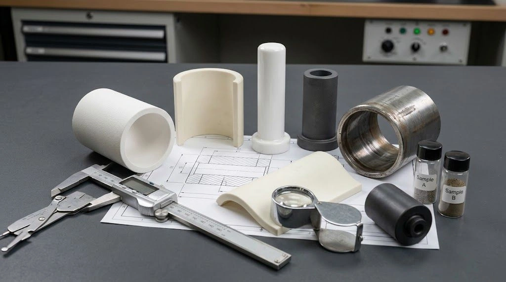
A replacement tube is an interface component. Temperature rating and nominal outside diameter are insufficient to establish fit, thermal behavior or atmosphere performance.
Provide a complete RFQ package
| Group | Information to provide |
|---|---|
| Work tube | Material, grade, purity, OD, ID, wall, overall length, end configuration and quantity |
| Seal interface | OD tolerance, roundness, straightness, surface condition, end-face requirements and engagement |
| Furnace | Model, orientation, bore, body length, heating zones, uniform zone and operating cycle |
| Cold-end layout | Projection on each side, sealing-contact locations, supports and available clearance |
| Seals | Manufacturer, model, exact O-ring compound and size, gland drawing, ports and feedthroughs |
| Process | Gas chemistry, purity, flow direction and range, vapors, vacuum and pressure differential |
| Cooling | Method, supply conditions, flow, pressure, water quality, monitoring and failure response |
| Acceptance | Leak requirement, cleanliness, temperature limit, measurement point and test conditions |
Specify the exact elastomer compound rather than only a family name or “high-temperature O-ring.” Temperature capability, gas compatibility, vacuum behavior and gland fit must be reviewed together.
A tube's general material data do not establish a pressure or vacuum rating for the installed system. Geometry, temperature, flaws, supports and loading remain relevant. The furnace integrator and seal supplier must review their interfaces; the tube supplier cannot certify unrelated hardware from tube dimensions alone.
Copyable RFQ wording
We require an extended alumina work tube for a sealed tube-furnace assembly. Please review the attached furnace, flange and support drawings. Specify material grade, OD/ID tolerances, overall length, cold-end projection on each side, flange engagement and sealing-surface requirements. Service conditions include [temperature cycle], [gas and flow], [vacuum or pressure differential] and [process vapors]. The assembly must meet [leak criterion] and [seal-temperature requirement at the agreed measurement location]. Please identify interface assumptions requiring confirmation by the furnace and seal suppliers.
When standard dimensions do not provide the required projection or flange fit, custom ceramic furnace tubes should be reviewed as part of the complete sealing assembly.
Frequently asked questions
How cool must the seal stay?
Within the approved range of the exact assembly under its actual service conditions. There is no universal flange-temperature limit.
Why can a high-temperature furnace use an elastomeric seal?
The seal is positioned and thermally managed in the projecting cold-end region. It is not expected to withstand the central process temperature.
Does every sealed tube furnace need water cooling?
No. The required cooling method depends on the thermal design and measured operating conditions.
Will a higher-temperature O-ring solve overheating?
Not necessarily. Chemistry, gland geometry and other attached components may remain limiting.
Why does vacuum deteriorate only when hot?
Possible causes include joint movement, seal deterioration and increased gas release. Diagnose these separately before replacing or tightening components.
Treat the cold end as part of the process system
Reliable sealing requires coordinated tube geometry, radiation control, cooling, alignment and support. Verify temperature and sealing performance over the intended cycle. An upgraded O-ring cannot compensate for an incorrectly positioned or mechanically overloaded assembly.