Ceramic fracture toughness, commonly reported as KIC in MPa·m¹ᐟ², describes a material’s resistance to the extension of an existing Mode I crack under specified test conditions. It is not the stress required to break a component, and it should not be read as strength, impact resistance, or guaranteed service life. A useful KIC value must be accompanied by the ceramic grade, test method, specimen and crack geometry, test environment, and result statistics.
What Does KIC Mean for a Ceramic?
Fracture toughness describes resistance to crack extension, not resistance to the creation of every possible defect. In linear-elastic fracture mechanics, the Mode I stress-intensity factor is commonly written as:
[K_I = Y\sigma\sqrt{\pi a}]
Here, (\sigma) is applied tensile stress, (a) represents crack size, and (Y) is a dimensionless factor that accounts for crack and component geometry. Crack extension becomes possible when the applied stress intensity reaches the relevant critical resistance. This relationship explains why the same material can tolerate one flaw in a lightly loaded geometry but fail from a smaller flaw near a severe stress concentration.
KIC is often used as shorthand, but engineers should avoid calling every reported ceramic toughness value a plane-strain KIC without checking the governing method and validity requirements. A more defensible interpretation is “the reported Mode I fracture resistance produced by the stated method.”
KIC Is Not Flexural Strength
Flexural strength records the stress at which a particular specimen fails in bending. It is strongly influenced by the specimen’s size, surface finish, machining damage, edges, and statistical flaw population. Fracture toughness instead addresses how strongly an existing crack resists extension under a defined crack-mechanics test.
| Property | What It Describes | Typical Unit | Main Limitation |
|---|---|---|---|
| Fracture toughness | Resistance to extension of an existing crack under defined conditions | MPa·m¹ᐟ² | Method and crack configuration must be known |
| Flexural strength | Failure stress of a specimen under bending | MPa | Strongly affected by flaw population, size, and surface condition |
| Compressive strength | Failure stress under compression | MPa | Does not represent tensile-crack sensitivity |
| Hardness | Resistance to localized indentation | GPa, HV, or HRA, depending on method | Does not directly measure crack-growth resistance |
A ceramic may show high flexural strength because its test specimens contain few severe surface flaws, yet offer only moderate resistance once a sharp crack exists. Conversely, a lower measured strength does not prove that the material has lower intrinsic crack-growth resistance.
KIC Is Not Hardness
Hardness measures resistance to localized indentation or penetration. It can be relevant to scratching and some wear mechanisms, but it does not directly describe crack propagation. A hard ceramic can still be sensitive to sharp edge defects, machining cracks, or tensile contact stresses. Hardness and KIC therefore belong in separate specification fields.
A First-Pass Critical-Flaw Calculation
Rearranging the stress-intensity relationship gives a simplified estimate of a critical flaw size:
[
ac \approx \frac{1}{\pi}\left(\frac{K{IC}}{Y\sigma}\right)^2
]
This is useful for sensitivity studies: increasing stress or changing geometry can reduce the flaw size associated with critical propagation. It is not an allowable production-flaw formula. Real design still requires verified geometry factors, residual-stress assessment, applicable environmental and time effects, statistical strength data, inspection capability, and an appropriate safety margin.
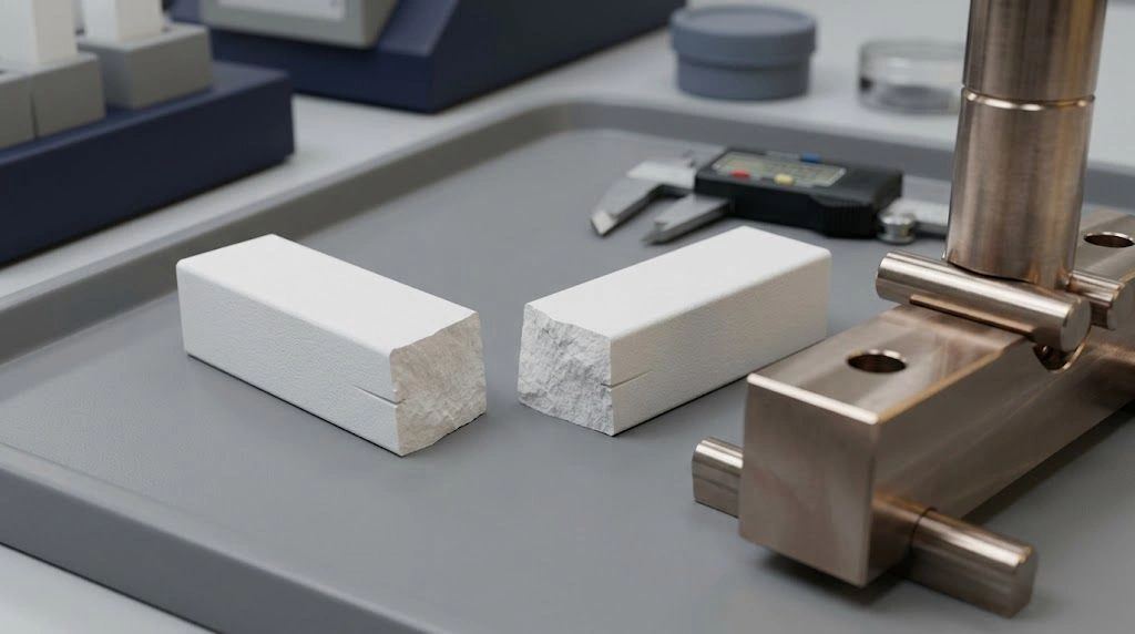
A fracture-toughness result describes the resistance of a prepared crack in a defined specimen and loading configuration.
How Is Ceramic Fracture Toughness Measured?
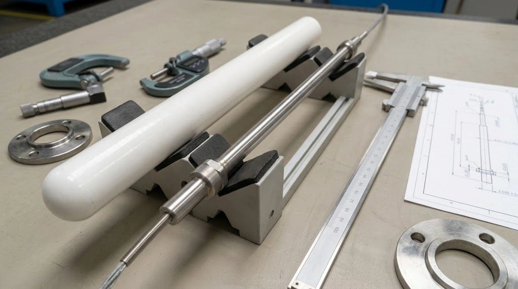
A ceramic toughness value becomes comparable only when its method and validity conditions are known. The development record for ASTM C1421 describes three beam-based approaches: single-edge precracked beam, surface crack in flexure, and chevron-notched beam. Each creates or controls a crack differently, so preparation, crack measurement, orientation, geometry, loading, and data reduction all matter.
International methods are also configuration-specific. For example, ISO 15732 covers SEPB, ISO 18756 covers SCF, and ISO 24370 covers CNB. The applicable edition must be checked when the test is specified; a standard number without its revision is incomplete procurement information.
| Method | Crack or Notch Configuration | Main Data Value | Important Comparability Check |
|---|---|---|---|
| SEPB / PB | Beam with a sharp precrack extending from one edge | Standardized crack-growth resistance from a precracked beam | Confirm precracking procedure, crack length, specimen orientation, and valid fracture |
| SCF | Controlled surface crack loaded in flexure | Toughness derived from a measured surface crack | Confirm indentation-damage treatment, crack measurement, orientation, and residual-stress correction |
| CNB | Chevron-notched beam designed to initiate and extend a crack | Toughness determined from chevron geometry and maximum load | Confirm notch geometry, stable crack behavior, dimensions, and valid calculation |
| SEVNB | Beam with a sharp V-notch | Method-specific toughness using a notched beam | Confirm notch-root radius and compliance with the applicable standard |
| Vickers indentation crack-length estimate | Cracks measured around an indentation | Equation-dependent apparent or indentation-derived value | Do not treat it as automatically equivalent to standardized beam-method KIC |
ASTM C1421 Methods
In SEPB, a sharp precrack is extended from one edge of a beam before fracture loading. SCF begins with a controlled surface flaw and uses flexure plus post-fracture crack measurement. CNB uses a chevron-shaped notch so crack initiation and extension are governed by the notch geometry and load response. The methods share a fracture-mechanics purpose, but they are not merely different laboratory routes to an automatically identical number.
Reference materials can help laboratories validate execution. NIST’s SRM 2100 program was developed to support fracture-toughness measurement and complements standardized testing. A reference material does not replace method control for an unknown grade; it helps reveal whether a measurement process is producing an expected result.
Why Notch Sharpness Matters
A machined notch has a finite root radius, while a natural crack tip is much sharper. If a notch-based procedure leaves the root too blunt, crack initiation may require more load, producing an apparent toughness above the resistance associated with a sharper crack. The acceptable preparation and validity criteria must therefore come from the exact method and revision—not from a universal shop-floor notch-radius rule.
Why Indentation-Derived Values Need a Warning Label
Vickers indentation estimates use crack lengths around an indent together with hardness, elastic modulus, load, and an empirical or semi-empirical equation. Crack pattern, polishing, residual stress, timing, optical resolution, and equation selection can all shift the answer. A NIST-hosted critical review concluded that the Vickers indentation fracture method is not a reliable fracture-toughness test for ceramics or other brittle materials.
Indentation data may still serve as a controlled internal screening metric. If used, report it as “indentation-derived” or “apparent,” and state the equation, load, crack pattern, surface condition, modulus, hardness, and crack-measurement procedure. Do not merge it into a beam-method comparison simply because the calculated unit is MPa·m¹ᐟ².
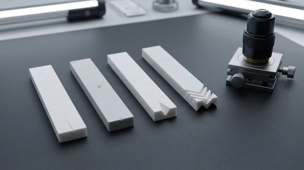
SEPB, SCF, CNB, and SEVNB specimens control cracks differently, so the method and preparation must travel with the result.
Why Can Two KIC Values for the Same Ceramic Differ?
Two values carrying the same KIC label may represent different materials, cracks, or resistance regimes. “Alumina,” “zirconia,” and “silicon nitride” name material families, not invariant formulations. Purity, additives, secondary phases, grain size, porosity, processing route, texture, surface condition, and residual stress can change crack behavior.
The test adds another layer. Precrack quality, notch-root radius, crack-length measurement, specimen size, loading configuration, test rate, temperature, and atmosphere can shift the reported value. A comparison is defensible only after both the grade and test conditions have been aligned.
Material Family Is Not Material Grade
For alumina, purity, grain structure, porosity, and secondary phases matter. For zirconia, stabilizer chemistry, phase balance, grain size, processing, and aging condition affect transformation behavior. Zirconia-toughened alumina also depends on zirconia content and dispersion. Silicon nitride behavior varies with elongated-grain morphology and intergranular phases; silicon carbide varies with densification route, secondary phases, density, and orientation. Aluminum nitride data depend on purity, sintering additives, porosity, and texture.
This is why a universal family ranking is misleading. A value for one zirconia grade does not characterize every zirconia, and an alumina value measured by SEPB should not be ranked against an unlabeled indentation estimate for another grade.
Rising R-Curve Behavior
Some ceramics do not exhibit a completely crack-length-independent resistance. Transformation toughening, crack bridging, and microcracking can make resistance rise as a crack extends, producing an R-curve. This behavior can be significant in some zirconia, zirconia-toughened alumina, and elongated-grain silicon nitride systems.
The reported number may correspond to crack initiation, resistance after a defined increment of extension, a maximum-load calculation, or a plateau. Ask what point on the resistance curve the value represents. Two correct results can differ if they capture different stages of crack growth.
Temperature, Atmosphere, and Time Effects
Room-temperature data in laboratory air may not represent hot, wet, corrosive, or long-duration service. Phase stability can alter zirconia toughening. Environment-assisted subcritical crack growth—often discussed as static fatigue in ceramics—can allow cracks to extend under stresses below the short-term critical condition. Loading rate can therefore matter, and KIC alone is not a lifetime curve.
Statistics and Reporting Precision
A report should state the number of valid specimens, mean, spread, invalid or rejected tests, and individual values where needed. Excessive decimal precision is a warning sign when method, sample count, and variability are absent. A single neat number can hide specimen-to-specimen scatter, preparation problems, or a mixture of valid and invalid fractures.
What Does KIC Predict—and What Does It Not?
KIC is directly useful when an engineer needs to assess how an existing crack interacts with tensile stress and geometry. It can support fracture-mechanics calculations, method-matched material screening, failure analysis, and inspection planning. It cannot independently predict whether a finished part will survive handling, impact, rapid heating, cyclic loading, chemical attack, or years of service.
| Engineering Question | Is KIC Relevant? | What Else Is Required? |
|---|---|---|
| Will an existing crack extend under tensile load? | Directly relevant | Crack size, stress, geometry factor, environment, and safety margin |
| Which material better resists crack growth? | Relevant when data are method-matched | Same method, grade, orientation, temperature, and statistical basis |
| Which ceramic has higher flexural strength? | Not sufficient | Flexural-strength data, specimen size, finish, and Weibull statistics |
| Will a part resist impact or edge chipping? | Partly relevant | Impact geometry, contact load, thickness, edge design, strength, and residual stress |
| Will a furnace part survive thermal shock? | Partly relevant | Expansion, modulus, strength, conductivity, geometry, and heat-transfer rate |
| Will a component last for a specified number of cycles? | Not sufficient | Cyclic or subcritical crack-growth data, stress history, environment, and reliability model |
| Is the material wear resistant? | Not sufficient | Hardness, counterface, load, lubrication, abrasive size, and wear-test conditions |
Toughness Is Not Impact Strength
A higher method-matched KIC may help resist the growth of cracks created during impact, but impact response also depends on mass, velocity, contact geometry, component thickness, support, strength, and energy absorption. Edge chipping from a hard point contact is not characterized by KIC alone.
Toughness Is Not Thermal-Shock Resistance
Thermal shock combines the temperature gradient with thermal expansion, elastic modulus, strength, thermal conductivity and diffusivity, geometry, wall thickness, surface condition, heat-transfer coefficient, and fracture resistance. Higher toughness can be beneficial, but “higher KIC means better thermal shock” is not a sufficient selection rule.
Toughness Does Not Remove the Need for Good Geometry
Sharp internal corners, abrupt wall transitions, thin unsupported edges, holes near tensile hot spots, assembly misalignment, point loading, and machining damage can all intensify local stress or introduce flaws. A carefully reported KIC value cannot compensate for a component design that concentrates tensile stress at a sharp corner or damaged edge.
What Should Buyers Request in a Ceramic Toughness Report?
The most useful supplier deliverable is not a lone KIC number but a traceable data package. At minimum, it should identify the exact material, test standard and revision, method, specimen orientation, crack preparation, environment, valid sample count, and result distribution. If the material may show a rising R-curve, the report should also define whether the value represents initiation, a stated amount of crack extension, or another method-specific point.
Supplier Data Checklist
- Exact material designation and grade.
- Composition, purity, stabilizer, additives, and secondary phases where relevant.
- Density and open-porosity condition.
- Manufacturing route and specimen orientation where relevant.
- Test standard and revision.
- Test method: SEPB, SCF, CNB, SEVNB, or a clearly labeled alternative.
- Specimen geometry and dimensions.
- Crack or notch preparation procedure.
- Measured crack length or notch-root information.
- Test temperature and atmosphere.
- Loading configuration and rate.
- Number of valid specimens.
- Mean, standard deviation, range, and individual values where needed.
- Invalid-test and fracture-origin criteria.
- R-curve definition or crack-extension point, if applicable.
- Batch or lot identification.
- Laboratory and equipment traceability.
- A statement distinguishing typical data from guaranteed acceptance limits.
Copyable RFQ Language
Please provide fracture-toughness data for the proposed ceramic grade, including the applicable test standard and revision, test method, specimen orientation, crack or notch preparation, test temperature and atmosphere, number of valid specimens, mean, and data spread. Identify any indentation-derived result explicitly and state whether the material exhibits reported R-curve behavior.
For a new component, review KIC together with geometry, tensile-stress locations, surface finish, grade, operating temperature, chemical environment, assembly load, and inspection requirements. Submit those details with the drawing when requesting custom ceramic parts so the property data can be evaluated against the actual component rather than treated as an isolated datasheet ranking.
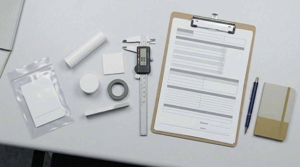
A usable toughness record identifies the material, method, specimen, crack preparation, environment, statistics, and reporting boundary.
Frequently Asked Questions
Is a higher KIC always better for a ceramic component?
A higher method-matched value indicates greater resistance to extension of an existing Mode I crack. It does not automatically mean higher strength, wear resistance, thermal-shock resistance, or service life. Geometry, surface damage, flaw distribution, environment, and loading still matter.
Can KIC values from two ceramic datasheets be compared directly?
Only when material grades, methods, orientations, temperatures, environments, and statistical bases are sufficiently aligned. Do not treat a beam-test value as equivalent to an unlabeled indentation-derived number merely because both use MPa·m¹ᐟ².
Is fracture toughness the same as flexural strength?
No. Flexural strength is the failure stress of a particular bending specimen and depends strongly on its flaws and surface condition. Fracture toughness describes resistance to extension of an existing crack under a defined method.
Is Vickers indentation suitable for KIC comparison?
It can serve as a controlled internal screen, but it should not be presented as automatically equivalent to standardized beam testing. Report the equation, load, crack pattern, surface condition, modulus, hardness, and crack-measurement procedure.
Why can zirconia toughness data vary so widely?
Results depend on stabilizer content, phase balance, grain size, processing, aging, temperature, crack extension, and method. Transformation toughening and R-curve behavior can also make the value depend on how the crack was initiated and measured.
Does KIC predict thermal-shock resistance?
Not by itself. Thermal-shock behavior also depends on expansion, modulus, strength, conductivity, diffusivity, wall thickness, geometry, surface condition, heat-transfer rate, and the actual temperature gradient.
Decision rule: Treat a ceramic KIC value as a method-qualified crack-resistance result. Compare the numbers only after the grade, method, orientation, environment, and statistical basis match—and never use KIC as a universal durability score.