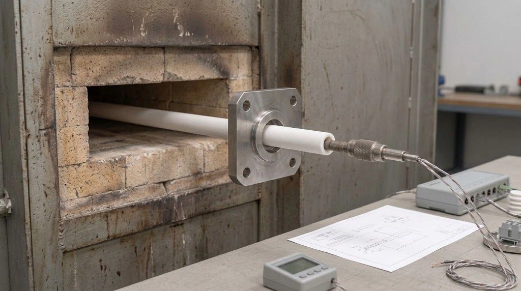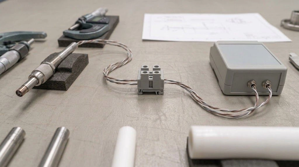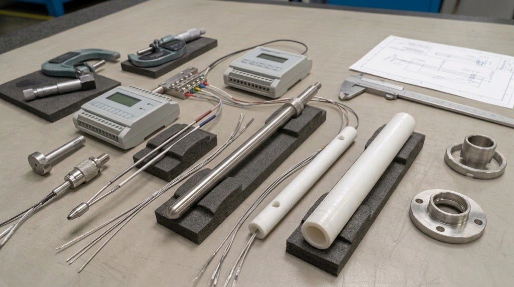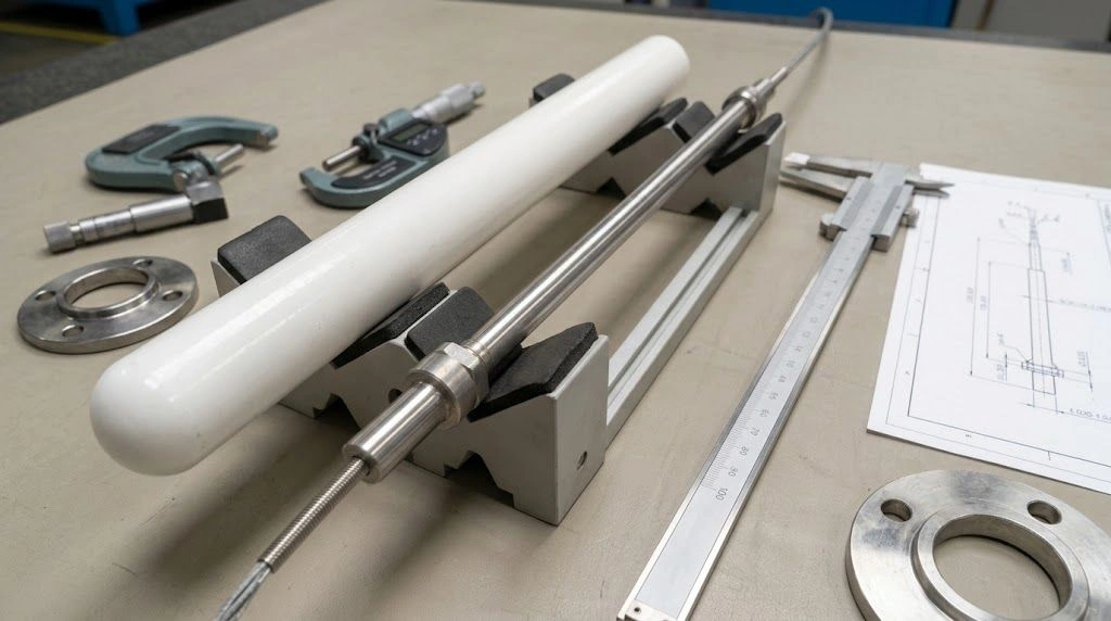
Ramp rate controls how quickly the furnace program moves toward a target temperature; soak time defines a hold under a stated temperature condition. A slower ramp may reduce temperature differences during heating. A suitable hold gives the load time to reach and remain in its process window. Neither parameter alone proves that a workpiece reached its required temperature. In a tube furnace, compare the programmed setpoint, measured furnace temperature, and representative load temperature before changing the recipe or specifying a ceramic work tube.
This matters when a new load heats slowly, a sample result changes, or a tube shows damage. The controller may follow its program while the load experiences a different thermal history. The tube also sees gradients and constraints that the workpiece procedure may not describe. Define measurement locations and the acceptance rule before changing the cycle.
What Do Ramp Rate and Soak Time Control?
A programmed ramp rate is the change in commanded temperature per unit time, often expressed in °C/min. The actual furnace sensor may lag the setpoint if heater capacity, heat loss, or load demand limits the response. A programmed hold is the controller segment that maintains a specified setpoint for a specified duration under its configured start rule. These are program definitions. They do not automatically describe the temperature at every point in a loaded tube.
Setpoint versus measured temperature
Separate three traces in the process record. First is the controller setpoint, which is an instruction. Second is the control thermocouple reading at its installation point. Third is the temperature at a representative workpiece or validated load location. The three may converge during a long stable hold yet differ substantially during heating or cooling. A sample near the end of a tube, a tightly packed boat, or a large part with a slow-heating core may behave differently from a small exposed witness piece in the central hot zone.
Equipment descriptions illustrate why published performance needs its measurement condition. Nabertherm identifies programmable furnace stages and describes a uniformity figure for an empty workspace. Carbolite Gero lists a controller with a ramp and process timer and states that its heat-up rate is measured with an empty chamber. These are examples of equipment documentation, not validated ramp limits or loaded temperature profiles for a particular alumina tube furnace.
Controller hold versus process hold
The controller's dwell timer may begin when its own start condition is satisfied. The process hold should be defined by the applicable workpiece procedure: which location must enter which allowable temperature range, for how long, and under what loading pattern. Sometimes a validated process deliberately uses the control sensor as a proxy for the load. In that case, document the evidence linking them. Without such evidence, “60 minutes on the controller” and “60 minutes at the required workpiece temperature” are different claims.
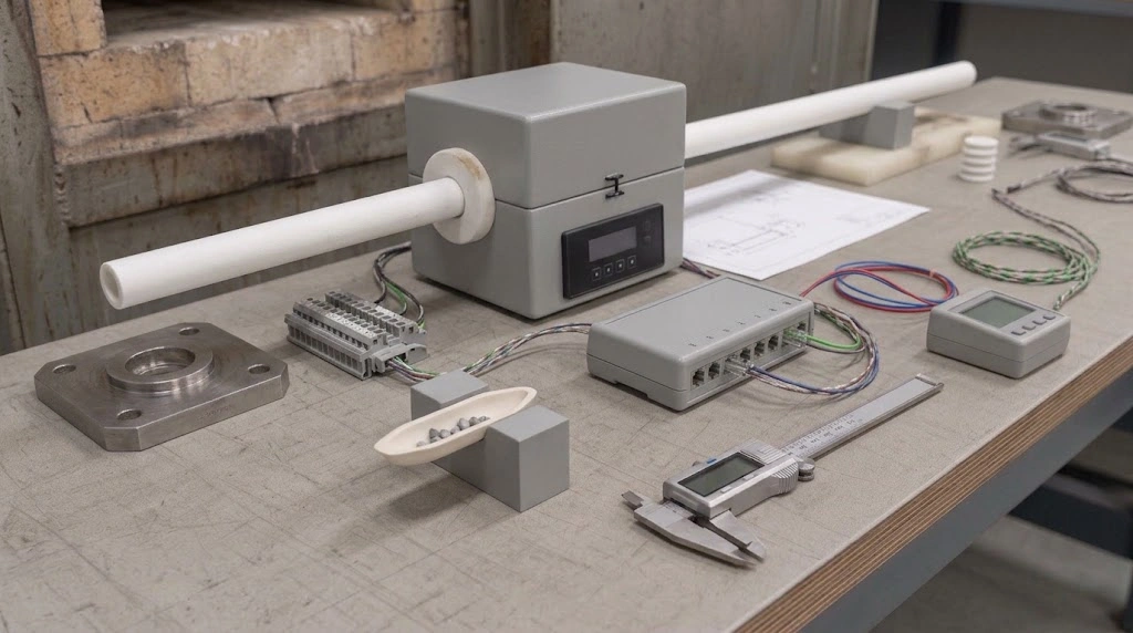
The programmed cycle and the temperature experienced by a loaded sample are separate records.
When Does the Load Actually Reach Soak Temperature?
For a load-based process, effective soak begins when the specified representative load locations have entered the approved temperature window and the procedure's timing rule is met. The furnace display reaching setpoint can precede that moment. A thick part heats from its surface inward; a packed load changes heat transfer between pieces; and a sensor in the furnace wall or air space is not located at the slowest-heating part. The delay is specific to geometry, placement, atmosphere, and the cycle.
Sensor placement and a representative load
Specify what the sensor is intended to represent. A control thermocouple governs the heater, but its position might be outside the work tube or offset from the sample. A load thermocouple can reveal a local history, provided its junction placement, attachment, and routing do not make the measurement misleading. For a batch with multiple positions, identify the locations expected to be hottest and slowest to heat, then use a suitable mapping or validation method. Nabertherm's service description lists temperature-uniformity measurement as a distinct service, reinforcing that uniformity is something to establish for a defined working space.
Use this sequence when reviewing a proposed soak start:
- Identify the governing requirement. State the load temperature window, required duration, and permitted variation from the material or process procedure.
- Locate the sensors. Mark control and representative load junctions relative to the hot zone, tube, boat, and parts.
- Fix the loading pattern. Record part dimensions, total load, spacing, boat material, and positions. A changed load can invalidate an earlier timing assumption.
- Observe arrival at temperature. Compare measured traces during a controlled trial at the intended cycle and atmosphere.
- Apply the approved clock rule. Start or credit the effective hold only as the validated process definition permits, and retain the evidence.
If direct workpiece measurement is impractical, validate the relationship between control-sensor and load temperature for a defined loading envelope.
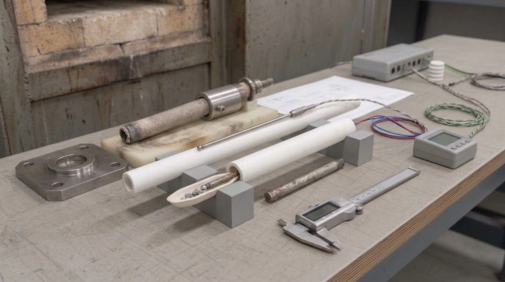
Define where the control and representative load sensors measure before assigning a soak start.
Misdiagnosis: Is the Problem the Ramp, the Hold, or the Measurement?
A changed result does not identify which setting is wrong. First compare the setpoint and measured furnace trace. Then look at the representative load trace under the same loading arrangement. Finally inspect the tube, support, sealing, and sensor positions. The table separates observations that often get combined under the vague instruction to “add more soak.”
| Observed condition | First action | Verification | Common wrong conclusion |
|---|---|---|---|
| Controller reaches setpoint while the representative load keeps warming | Check load sensor position and thermal lag | Compare both traces with the process window | Programmed hold equals full load soak |
| Large temperature difference develops across the load during heating | Review ramp, spacing, and location in the hot zone | Compare representative hot and cold positions | A longer final hold prevents every ramp-stage problem |
| Load enters its window, but credited time is short | Review the process hold-start rule | Log time within the validated window | A slower ramp replaces the required hold |
| A ceramic tube has a new visible crack after cycling | Preserve the evidence and review heating, cooling, support, fit, and prior condition | Inspect the part and cycle record with the supplier | The heating ramp alone caused the crack |
| Results vary with the same controller program | Check load arrangement, atmosphere, thermocouple condition, and uniformity | Repeat with defined positions and comparable loads | The program guarantees identical workpiece history |
The second and third rows lead to different changes. As an engineering inference from heat transfer, a longer final hold can allow later equilibration but cannot be assumed to undo damage or unwanted transformations that occurred during an earlier steep gradient. Conversely, a slower ramp cannot supply time in the required temperature window if the process demands a distinct hold after arrival. Test both against the workpiece objective and the tube's operating conditions.
For a cracked alumina tube, appearance alone cannot distinguish a steep ramp from cooling, tight seals, poor support, contact, chemical exposure, or prior damage. Preserve the as-found installation and cycle record for a joint review.
Sensor error can imitate a soak problem. A moved control thermocouple, changed insertion depth, wiring fault, or poor reference-junction compensation may shift the displayed trace. Confirm instruments and locations before extending a cycle that might already be adequate or overheating a different part of the load.
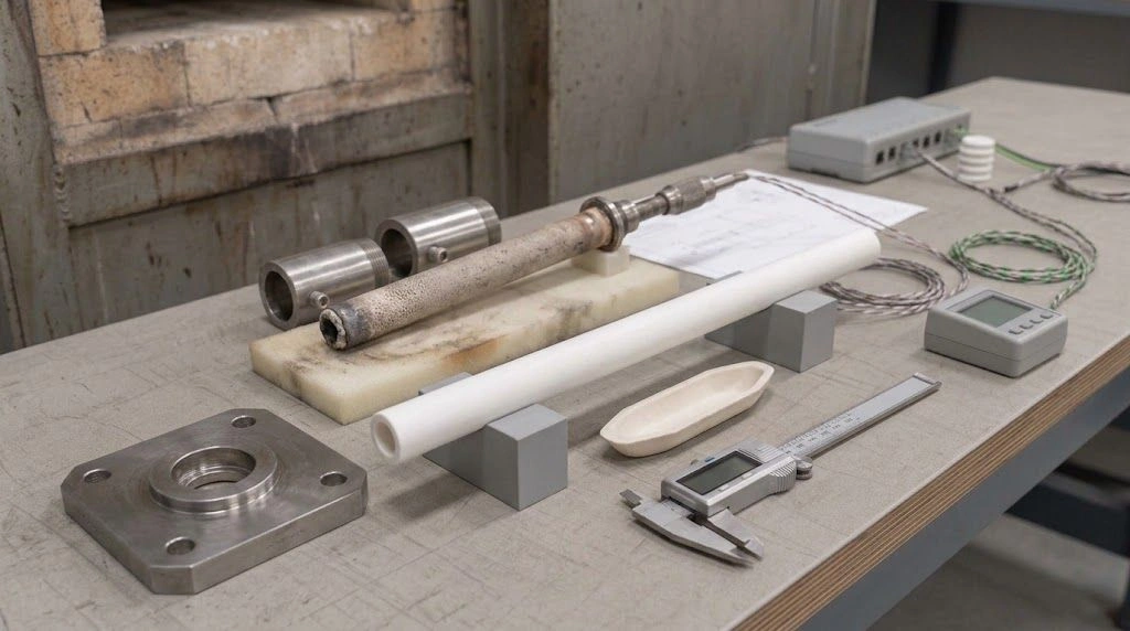
Review the tube, load support, and contact points alongside the temperature record.
How Should You Choose a Ramp and Hold for a Tube Furnace?
Start from the workpiece's validated treatment requirement and the furnace's documented operating limits. Then review the tube as a component with its own geometry, support, seal, atmosphere, and heating and cooling exposure. There is no single °C/min or soak-minute value that works across all alumina grades, tube sizes, loads, and process goals. A manufacturer's empty-furnace performance figure cannot certify the loaded cycle.
| Evidence from the intended run | Priority review | Verify before release |
|---|---|---|
| Wide load temperature spread while heating | Ramp shape, spacing, load size, hot-zone placement | Measured representative load positions during the proposed ramp |
| Furnace sensor at target but load still below window | Soak-start rule and load-to-control lag | Load arrival time under the intended loading pattern |
| Load in window but insufficient credited duration | Process hold duration | Time logged within the required window |
| Tube or end fittings constrained during expansion | Support span, seal clearance, and mounting | Drawing review and inspection across the cycle |
| Actual furnace trace cannot follow setpoint | Program demand, heater capability, and load | Logged setpoint and control-sensor traces |
| Different result after changing atmosphere or boat | Heat transfer and sample placement | Repeat measurement under the new configuration |
Change one condition at a time where possible and retain setpoint and measured traces. For tube concerns, review cooling and end supports as well as heating.
Specify separate acceptance checks for load temperature history and tube installation. Without load mapping or tube-specific limits, treat the proposed cycle as a trial requiring validation.
What Should Go Into the Furnace Tube Specification and RFQ?
A useful inquiry describes both the ceramic part and the thermal duty. Supply a dimensioned drawing for the alumina furnace tubes under review, with outside and inside diameters, wall thickness, overall length, hot-zone length, external projections, end finish, supported span, and the position of supports and seals. Indicate whether the tube is horizontal or vertical, whether it carries a boat or load directly, and where any openings, sensor ports, or fittings sit. Mark dimensions whose tolerances affect mating parts or seal contact.
Add the requested material grade and any purity or contamination requirement, then state normal and peak process temperature, heating and cooling profile, hold definition, cycle frequency, atmosphere, pressure or flow conditions, load mass and placement, and contact materials. If an existing tube failed, send labeled photographs and its prior duty record without claiming a cause from appearance alone. Ask the supplier which information is still needed to assess geometry, fit, and service compatibility.
Attach the measurement plan: controller sensor location, any representative load sensors, target temperature window, soak-start rule, and how the loaded trial will be accepted. The ceramic supplier can review the tube and mounting feasibility; the process owner validates the heat treatment of the load. Record the approved drawing and operating envelope so the next replacement and next run reproduce the conditions that were actually checked.